La Crosse Technology WS-2308AL Operating instructions
- Category
- Weather stations
- Type
- Operating instructions
This manual is also suitable for

1
Operation Manual
Professional Remote Weather Station
Table of Contents
Page
1. Introduction………………………………………………............. 2
2. Intended use………………………………………….................. 2
Weather Station……………..................................................... 2
System requirements for PC use………….............................. 3
Features of the base station…………...................................... 3
Features of the thermo-hygro sensor…………........................ 4
Features of the wind sensor…………...................................... 4
Features of the rain sensor...................................................... 4
3. Safety Notes............................................................................ 4
4. Packaged contents.................................................................. 5
5. Setting up................................................................................. 6
6. Operation using cable connection or wireless 433MHz.......... 8
7. LCD overview ........................................................................ 10
8. Function test .......................................................................... 11
9. Mounting................................................................................ 11
10. Resetting & factory settings................................................... 14
11. Function description............................................................... 16
12. Operation keys....................................................................... 19
13. Basic programming modes.................................................... 21
14. MIN/MAX programming modes............................................. 22
15. Alarm programming modes................................................... 23
16. Auto-memory for stored values ............................................. 31
17. Accessories: extensions cables............................................. 32
18. Changing batteries................................................................. 33
19. Problems and interference with operation............................. 34
20. Transmission range............................................................... 35
21. Cleaning and maintenance.................................................... 35
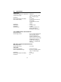
22. Specifications......................................................................... 36
23. Warranty Information............................................................. 38
This Operation Manual is part of this product and should be kept in a
safe place for future reference. It contains important notes on setup and
operation.
Please see www.heavyweather.info
for a complete IM, FAQ and
downloads of the most current software.

2
1. Introduction
Thank you for purchasing this Professional Remote Weather Station.
Designed for everyday use, the weather station will prove to be an
asset of great value for your personal use in the home or office.
Please read this instruction manual thoroughly to fully understand the
correct operation of your weather station and benefit from its unique
features.
2. Intended Use
Weather Station
The base station measures the indoor environment of its surrounding
area and receives weather data from the following three outdoor
sensors:
1) Thermo-Hygro Sensor
2) Wind Sensor
3) Rain Sensor
The received data is continuously updated to bring you the latest
weather information on the base station’s LCD. The outdoor thermo-
hygro sensor is the main data communication unit since both the wind
and rain sensors are connected to the thermo-hygro sensor for
operating power and rely on it to communicate to the base station.
Weather data sent from the thermo-hygro sensor can be done by
wireless 433MHz transmission (up to 330ft in open space) or by cable
connection.
Using the enclosed 6.5ft computer cable and CD-ROM, you can
install the Heavy Weather software to your PC and access the latest
weather information from your PC and upload up to 175 sets of
recorded weather data received by the base station. Recorded data
can be used to generate statistics and charts onto your spreadsheets
(175 sets of data is stored in the base even if the PC is switched
OFF). The software itself does not set any limits as to how many data
sets can be transferred to PC.
This weather station is designed to work easily with your PC, simply
connect and disconnect the PC cable at any time.

3
System Requirements for PC use:
The minimum system requirement for use of this “Heavy Weather”
software is:
Operating system: Windows 98 or above
Processor: Pentium 166 MHz or above
RAM: 32MB of RAM or above
Hard disk: 20MB free space
CD-ROM drive
For full details on operation and installation of the “Heavy Weather”
software refer to the PC manual in PDF format on the CD-ROM.
Features of the base station:
• Receives and displays the WWVB radio controlled time and date
• Display of extensive weather data, in all cases with programmable
alarm functions for certain weather conditions as well as records of
all minimum and maximum values along with time and date of their
recordings
• Indoor and outdoor temperature displays in degrees Fahrenheit or
Celsius (user selectable)
• Indoor and outdoor relative humidity displays
• Air pressure reading in inHg or hPa, absolute or relative (user
selectable)
• Detailed display of rainfall data in 1 hour, 24 hours, total since last
reset (user selectable in mm or inch)
• Wind speed in mph, km/h, m/s, knots or Beaufort (user selectable)
• Wind direction display with LCD compass as well as numerical (e.g.
225°) and abbreviated characters (e.g. SW)
• Wind chill temperature display
• Dew point temperature display
• Weather forecast display by weather icons (sunny, cloudy, rainy)
• Weather tendency indicator
• Storm warning alarm
• E.L. back light
• Simultaneous display of all weather data with individual settings by
the user
• COM port for easy connection to your PC
• All the weather data from the base station and up to 175 sets of
weather history data with user adjustable measuring intervals can be
recorded and uploaded to your PC

4
Features of the Thermo-Hygro Sensor
The thermo-hygro sensor measures the outdoor temperature and relative
humidity. It also collects the readings from the rain and wind sensors
before transmitting the data to the base station by wireless 433MHz or by
the 32ft cable included in this set.
Features of Wind sensor
The wind sensor measures wind speed and wind direction and sends the
data to thermo-hygro sensor, which in turn transmits the data to the base
station. Operating power is taken from the thermo-hygro sensor using a
32ft cable connection.
Features of Rain sensor
The rain sensor measures the rainfall and sends the data to thermo-hygro
sensor, which in turn transmits the data to the base station. Operating
power is taken from the thermo-hygro sensor by a 32ft cable connection.
3. Safety Notes
• Damage caused by failure to comply with this instruction manual will
invalidate any guarantee! The manufacturer and supplier will not be
held liable for damages due to failure to comply with this instruction
manual or from data inaccuracies that may occur with this product!
• In case of harm or damage to a person or property caused by
improper handling or failure to comply with this instruction manual,
the manufacturer and supplier cannot be held liable.
• For reasons of safety and operation, alterations to this device are
strictly prohibited.
• To operate the weather station, use only supplied adaptor and
batteries of the recommended type.
• Do not leave discharged batteries in the device as these may
corrode and release chemicals that may damage the unit.
• Inserting batteries in an incorrect polarity will cause damage to this
product.
• This product is not a toy kept out of the reach of children.
• Do not dispose of new or used batteries in a fire as they may
explosion or release dangerous chemicals.
• This product is not to be used for medical purposes or for public
information.
• Any modification or alteration to this product is strictly prohibited
without the manufacturer’s authorization and may prohibit the user’s
further use of this product.

5
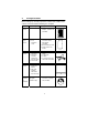
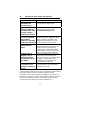
4. Packaged Contents
Before setting up, carefully unpack the contents onto a table or flat
surface and check that the following are complete:
Item: Consisting of: Fittings: Illustration:
Base
Station
• Main unit
• AD/DC 120V power
Adaptor - optional use
(included)
Thermo-
Hygro
Sensor
• Main unit
• Rain
protection
cover
• 32ft cable - optional
connection to the
base station
(included)
• Wall mounting screws
• Plastic anchors for
screws
Wind
Sensor
• Main unit with
wind vane
• 32ft cable
(already
attached to
the main unit)
• Mast holder
• 2 x U-bolts for mast
holder
• 4 x Washers
• 4 x Nuts
• 1 x screw (to fix main
unit to the mast holder
Rain
Sensor
• Main unit
(base and
funnel)
• 32ft cable
(already
attached to
the main unit)
Heavy
weather
PC
software
CD-Rom format
(English
version only)
• 6.5ft PC cable for PC
connection - optional
use (included)

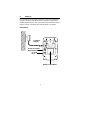
6
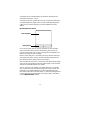
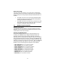
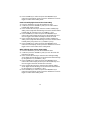
Battery compartment
Socket for Thermo-
Hygro Sensor
Socket for
Adaptor
PC COM
Port
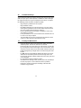
5. Setting up
First, choose to use the adaptor (included in this set) or batteries for
operation. Both these methods allow for operation using wireless
433MHz transmission or cable connection between the base station
and the sensors and setting up for both methods is as follows:
Base Station:

7
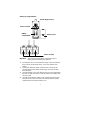
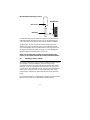
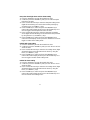
Setting up using batteries:
Important: To avoid operating problems, please take note of
battery polarity if inserting any batteries
1) Pull away the rain cover of the thermo-hygro sensor to reveal the
three sockets (for the wind sensor, rain sensor and the base
station)
2) Connect the attached cables of wind and rain sensors to the
corresponding sockets of the thermo-hygro sensor by clicking
them into place
3) Open the battery cover of the thermo-hygro sensor located below
the three sockets and insert 2 x AA, IEC LR6, 1.5V batteries and
close the cover
4) Open the base station’s battery cover located at the back of the
unit and insert 3 x AA, IEC LR6, 1.5V batteries into the battery
compartment and close the battery cover
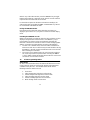
Sensor sockets
Battery
Compartment
Battery Cove
r
Thermo-Hygro Senso
r
Sensor sockets

8
Setting up using the AC adaptor:
1) Power up all the sensors as described in setting up using
batteries above
2) Using the AC adaptor (included), plug it into the mains outlet and
power up the base station by inserting the adaptor jack into the
DC 6.0V socket located on the side of the base station
Every time the thermo-hygro sensor is powered up (for example after
a change of batteries), a random security code is transmitted and this
code must be synchronized with the base station to receive weather
data.
When the base station is powered up, a short beep will sound and all
LCD segments will light up for about 5 seconds before it enters into a
15 minute learning mode to learn the sensors security code. After the
learning mode (or by pressing the MIN/MAX key at anytime), the base
station will start the WWVB radio controlled time reception.
Note for WWVB Radio Controlled Time:
The time and date display is based on the signal provided by the
highly accurate government operated atomic clock in Ft. Collins,
Colorado. This radio-controlled clock does not only provide for the
weather station’s time and date display but also functions as the time
and date source for all of this weather station’s memory and history
values using time and date information.
E.L. backlight:
When using the power adapter or under battery operation, the E.L.
backlight will switch on for 15 seconds when any button is pressed.
6. Operation using cable connection or wireless 433MHz
Cable Connection:
Using this method of operation will provide interference free transfer
of the weather data from the sensors to the base station. The data
sending interval from the sensors to the base station will also be more
frequent compared to using 433MHz transmission and will result in
higher power consumption. Therefore batteries will have a shorter life
span for cable connection compared to using 433MHz.
To operate using cable connection, simply use the enclosed 32ft
cable and connect the thermo-hygro sensor to the base station.

9
Once the connection is detected, the base station will automatically
continue reading the data from the sensor.
The user may at any time switch from cable connection to using
433MHz (or vice versa) by simply disconnecting (or connecting) the
cable from the base station to the sensor. When the base station
detects no cable connection to the sensors, the base station will
automatically change to using 433 MHz for reception of the weather
data from the sensors.
The data receiving intervals are as follows:
- Using cable connection data is updated every 8 seconds.
- Using wireless 433 MHz data is updated from 16 to 128 second
intervals depending on wind speed and rain activity.
Using the AC adaptor to operate the base station will also supply
power to the sensor if the cable is connected to it. Batteries used for
433MHz transmission may be left in the sensor when using cable
connection for power back up in case of AC power failure. A loss of
power would desynchronize the base station and the sensor and no
weather data will be received. To Synchronize the units so that the
weather data can be received, press and hold the PLUS (+) key for 2
seconds. However in general, batteries that will not be used for long
periods should be removed to avoid leakage.
Wireless 433MHz transmission:
Using 433MHz wireless transmission of weather data from the sensor
to the base station will provide users greater freedom as to where
units can be positioned without the need to be restricted by cable.
Note:
If no outdoor weather data is displayed or the signal to the sensors is
lost during setting up, mounting, changing of batteries to the sensor
or plugging or unplugging cables, simply press and hold the PLUS (+)
key for 2 seconds and a short beep will sound to synchronize the
base station to sensors. Without being synchronized, weather data
will not be received.

10
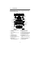
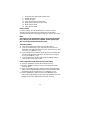
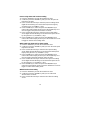
1. Low battery indicator
2. WWVB radio controlled time icon
3. Date display
4. Time zone display
5. Date, seconds, alarm time and time
zone
6. Alarm icon
7. Weather forecast icons
8. Weather tendency indicator
9. Pressure alarm display
10. hPa/inHg air pressure unit
11. Pressure units (relative or absolute)
12. 433MHz reception icon
13. Rainfall display
14. Indoor, outdoor, humidity, dew point,
wind chill, rainfall alarm icon
15. 24h, 1h or total hour display
16. Humidity display as RH%
17. Rainfall units (inch or mm)
18. Temperature display units (ºC or ºF)
19. Outdoor temperature/humidity display
20. Indoor temperature/humidity display
21. Dew point temperature display
22. Wind chill temperature display
23. Wind alarm icon
24. Wind information for Min/Max speed
and wind speed low, high, direction
alarm
25. Wind direction and speed (m/s, knots,
Beaufort, km/h or mph) display
26. Alarm buzzer ON/OFF icon
27. General alarm icon
16
1
2
3
4
5
6
7
8
9
10
13
12
14
15
17
23
11
19
20
22
21
18
24
25
26
27
7. LCD Overview
The following illustration shows the full segments of the LCD for
description purposes only and will not appear like this during
normal operation and use.

11
8. Function test
Once the weather station is powered up, perform a function test by
checking that the weather data is received. To do this, press the
DISPLAY, PRESSURE or WIND keys to toggle through the relevant
LCD sections:
1) Indoor temperature and humidity
2) Outdoor temperature and humidity
3) Outdoor wind chill
4) Dew point
5) Rainfall 24 hour
6) Rainfall 1hour
7) Rainfall Total
8) Relative and absolute pressure
9) Wind speed, wind direction and wind direction in degrees
If any readings cannot be received from the sensors, lines (- - -) will
be displayed in the respective weather sections of the LCD. In this
case, check that all cables are correctly inserted into the correct
sockets and/or check the batteries in the outdoor thermo-hygro
sensor and press and hold the PLUS (+) key for 2 seconds and a
short beep will sound to synchronize the base station to the sensors
otherwise no weather data will be received..
Some weather readings such as wind speed and direction may not
appear immediately on the LCD if the wind-fan or vane of the wind
sensor is moved. This is due to the set reading time intervals for the
wind readings. However the current wind speed or direction will be
displayed once the time reading interval is reached. For rainfall, the
interval readings may take up to 2 minutes before the data is
displayed on the LCD.
9. Mounting
Important Note
Prior to drilling mounting holes and permanently affixing any of the
units, please ensure the following points are considered:
• Cable lengths of the units meet with your distance requirements
at the point of fixing
• Signals from the sensors can be received by the base station at
points of mounting

12
• Radio controlled time signal can be received at the point of
mounting
NOTE: The WWVB receiver is located in the base station.
Base Station
With two foldable legs at the back of the unit, the base station can be
placed onto any flat surface or wall mounted at the desired location
by the hanging holes also at the back of the unit. It is important to
check that the 433MHz (if using wireless connection) and the WWVB
radio controlled time signal can be received before permanently
mounting any of the units. Should the base station not display the
433MHz weather data from the sensors or the radio controlled time
from the desired location, then relocate the units. Once the signals
are received, the system can be affixed. Also if you have selected to
use cable connection, ensure that distances can reach all desired
locations before affixing any unit permanently
NOTE: For reception of WWVB time/date signal, do not mount the
base station closer than 5 feet from a computer, florescent lights or
other electrical appliances. Do not mount the base station on a wall
that has metal heat/AC ductwork in the wall behind the base station.
For best WWVB reception place the base station near a window
facing Colorado. WWVB reception will be obtained easiest in the
nighttime hours when the WWVB signal is strongest.
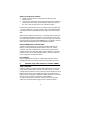
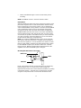
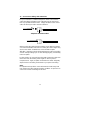
Mounting the Wind Sensor onto a mast
Firstly, check that the wind-fan and the wind-vane can rotate freely
before fixing the unit. For correct and accurate readings it is
important to mount the sensor so that the front (marked E) is pointing
in East-West direction. The wind sensor should now be mounted
using the screw provided onto a mast to allow the wind to travel
Wind-fan
Wind-vane
Mast

13
around the sensor unhindered from all directions (ideal mast size
should be from Ø0.63” – Ø1.3”).
Once the wind sensor is fixed onto the mast, connect the cable to the
corresponding thermo-hygro sensor socket so that operating power
supply can be received and data can be transmitted to the base
station.
Mounting the Rain Sensor
For accurate results, the rain sensor should be securely mounted
onto a horizontal surface about 2-3ft above the ground and in an
open area away from trees or other coverings where rainfall may be
reduced causing inaccurate readings.
When securing into place, check that rain excess will not collect and
store at the base of the unit but can flow out between the base and
the mounting surface (test by pouring clean water).
After mounting the rain sensor, connect the cable to the thermo-hygro
sensor at the corresponding socket so power supply can be received
and data be transmitted to the base station
The rain sensor is now operable. For testing purposes, very slowly
pour a small amount of clean water into the rain sensor funnel. The
water will act as rainfall and will be received and displayed at the
base station after about 2 minutes delay i.e. when the reading interval
is reached (to clear this testing data on the base station, refer to the
section “MIN/MAX Mode” below).
Base portion
Funnel portion

14
Mounting the thermo-hygro Sensor
An ideal mounting place for the thermo-hygro sensor would be the
outer wall beneath the extension of a roof, as this will protect the
sensor from direct sunlight and other extreme weather conditions.
To wall mount, use the 2 screws to affix the wall bracket to the
desired wall, plug in the thermo-hygro sensor to the bracket and
secure both parts by the use of the supplied screw and ensure that
the cables from the wind and rain sensors are correctly plugged in
otherwise data transmission errors could occur.
NOTE: For best 433 MHz reception mount the thermo-hygro
sensor on an outside wall near the location of the base station.
10. Resetting & factory settings
As previously mentioned, in the event of a power reset to the sensor
(for example a change of batteries), the base station has to
synchronize to the sensor again otherwise no weather data will be
received. To do this, simply press and hold the PLUS (+) key for 2
seconds and a short beep will sound to synchronize the base station
to the sensor. When the units are synchronized, the data will be
received again and the base station will return to normal operation
mode.
Do not remove batteries or unplug the AC adaptor of the base station
otherwise all 175 sets of recorded weather history data for
Rain Cover
Wall Bracket
Main Unit

15
transferring to the PC will be lost (for full details of PC use, please see
PC user manual in the enclosed Heavy Weather CD-ROM).
However if you wish to make a full reset of the base station and return
to the original factory settings, simultaneously press and hold the
PRESSURE and WIND keys for about 5 seconds. The base station
will beep once and the entire LCD will light up for 5 seconds and go
back to the original factory settings. This process with clear all
previous user defined values and all weather history recordings.
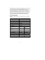
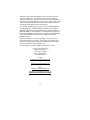
Factory default settings:
The following table shows the factory default values of the weather
station:
Matter: Default Setting:
Time 12:00 am
Date 01.01.2001
Time zone -5 ET
Alarm time 12:00 am
Relative air pressure 29.91 inHg
Weather-picture threshold 0.09 inHg
LCD contrast level 5 (1-8 levels)
Rainfall per impulse 0.0204 inches
Storm alarm 0.09 inHg
Relative air pressure
alarm
28.34 inHg
(low)
30.71 inHg
(high)
Indoor temperature alarm 50ºF (low) 86ºF (high)
Outdoor temperature
alarm
32ºF (low) 104ºF (high)
Indoor humidity alarm 35%RH (low) 65%RH (high)
Outdoor humidity alarm 45%RH (low) 70%RH (high)
Wind chill alarm 50ºF (low) 86ºF (high)
Dew point alarm 32ºF (low) 68ºF (high)
Rainfall 24h alarm 1.96 inches
Rainfall 1h alarm 0.03 inches
Wind Speed 1.0 mph (low) 62 mph (high)
Wind direction alarm None set

16
Note:
All alarm default values are deactivated at the start up and any alarm
must be activated by the user otherwise it will not sound.
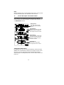
11. Function Description of the Weather Station
After setting up, the following data will be displayed in different
sections on the LCD. If this is not the case please observe the notes
on “Interferences” below.
Time & Date (LCD Section 1)
If the WWVB icon (icon 2) is ON and not flashing, it means that the
WWVB radio-controlled time and date are has been received. Press
the PLUS (+) key to change the format of date display between
date/month/year, weekday/date/month, seconds, alarm set time and
time zone.
LCD Section 1:
Time, date, seconds, time
zone, and respective alarms
sections
LCD Section 3:
Indoor and outdoor temperature
and relative humidity, wind chill,
dew point, rainfall, and respec-
tive alarms sections
LCD Section 4:
Wind direction, wind speed,
and respective alarms sections
LCD Section 2:
Weather forecasting icons with
tendency arrows, air pressure,
and respective alarms sections

17
Sunny Rainy Cloudy
Weather forecasting (LCD Section 2)
The three weather icons Sunny, Cloudy and Rainy represent the
weather forecasting. There are also two weather tendency indicators
to show the air pressure tendency either side of the weather icons.
Notes to inHg sensitivity setting for weather forecasting:
The inHg pressure sensitivity can be set to suit the user’s requirement
for weather forecasting from 6 inHg, 9 inHg to 12 inHg (see Basic
Programming below). For areas that experience frequent changes
in air pressure (which does not necessarily reflect a change in the
weather) requires a higher inHg setting compared to an area where
the air pressure is stagnant. For example if 6 inHg is selected, then
there must be a fall or rise in air pressure of at least 6 inHg before the
weather station will register this as a change in weather.
Air Pressure (LCD Section 2)
The air pressure reading is displayed here. Press the PRESSURE
key to toggle between relative and absolute air pressure displays.
Notes to Absolute and Relative Air Pressure:
Absolute air pressure provides the display of the true measured air
pressure of the current time and location. This is not programmable
and the absolute air pressure range of the weather station is from
8.85 inHg to 32.45 inHg (standard air pressure at an altitude of
30,000ft is around 8.85 inHg).
Relative air pressure is the one value that is calculated back to sea
level from the local absolute air pressure and can thus be taken as a
reference for weather condition and weather development for the
entire country. It can be programmed to represent your local
surroundings. Since the relative air pressure is also the one value
given by various newspapers, TV and radio broadcasting stations in
their daily weather forecasts for their respective locations, users can
set the relative air pressure of the weather station to this value to
represent readings your their area (see Basic Programming Modes
below).

18
Weather Data (LCD Section 3)
Indoor temperature and humidity are displayed simultaneously in this
section. Use the DISPLAY key to toggle through the displays for other
weather information:
- Outdoor temperature/humidity
- Outdoor wind chill
- Outdoor dew point
- Rainfall 24h
- Rainfall 1h
- Rainfall total.
Notes to Dewpoint and Windchill:
Air can at a certain temperature only carry a certain amount of water
(water vapor), which also increases and decreases with temperature.
If the air temperature decreases below the dewpoint (saturation
point), the excessive water vapor will condense and fall out in form of
dew, fog or rain. At a temperature of e.g. 59°F and a relative humidity
of 50% the dewpoint will be about 41°F, at 80% humidity about
53.6°F. At a relative humidity of 100% saturation is reached, i.e. the
dewpoint is 59°F. At a dewpoint below freezing the fallout will become
frost or snow.
Windchill has been introduced for battle planning during World War II.
It represents not the real measured but the temperature a person
feels in open area under the influence of wind and cold. Windchill is
laid out in tables for various temperatures and wind speeds. At an
outdoor temperature of e.g. 46.4°F and calm winds a person moving
at a speed of 13 mph will already feel a windchill temperature of 32°F.
Wind Data (LCD Section 4)
The current wind direction will be displayed on the LCD compass on
the wind section. Press the WIND key to toggle between wind
direction as numerical (e.g. 225°) and abbreviated characters (e.g.
SW) as well as numerical wind speed display inside the compass
circle.

19
12. Operation keys
The base station has 8 keys for easy operation. Please refer to the
following table for use and function of each key: Further descriptions
of the key functions with regard to their immediate range of
application can be found in the Programming modes:
SET - key
- In normal mode to enter the manual basic
programming mode
- In basic programming mode to select the
following setting modes:
- LCD contrast setting
- Manual time setting (hours/minutes)
- 12/24 time format display
- Calendar setting (year/month/date)
- Time zone setting
- °C/°F temperature setting
- Wind speed unit setting
- Rainfall unit setting
- Pressure unit setting
- Relative air pressure setting
- Weather picture threshold setting
- Storm warning setting
- Audible storm alarm setting
- In setting modes confirmation of the selected
values
- In alarm modes alarm ON/OFF
- In alarm mode to enter programming of alarm
values (long pressing)
- To exit MIN/MAX modes
PRESSURE
- key
- Toggle between Absolute and Relative air
pressure displays
DISPLAY -
key
- Toggle between the following current/ maximum/
minimum display modes:
- Indoor temperature and humidity
- Outdoor temperature and humidity
- Outdoor wind chill
- Outdoor dew point
- Rainfall (24h, 1h, total)
WIND - key
To toggle between the following settings:
- Wind speed
- Wind direction
- Wind direction display in degrees

20
ALARM -
key
- In normal mode to enter the alarm programming
mode
- In alarm programming mode to select the
following setting modes:
- Time alarm setting
- Indoor temperature alarm (high & low)
- Outdoor temperature alarm (high & low)
- Indoor humidity alarm (high & low)
- Outdoor humidity alarm (high & low)
- Outdoor wind chill alarm (high & low)
- Outdoor dew point alarm (high & low)
- Rainfall alarm (24h, 1h)
- Pressure alarm (high & low)
- Wind speed alarm (high & low)
- Wind direction alarm
- In setting modes confirmation of the selected
values
- To exit MIN/MAX modes
- To reset general alarm symbol
MIN/MAX -
key
- In normal display mode to toggle between
display of MIN/MAX values
- To toggle between MIN/MAX values in MIN/MAX
mode
- To exit any programming mode
PLUS (+) –
key
- In normal display mode to toggle between format
of date display, seconds, time alarm and time
zone
- To increase the values in the setting modes
- To exit MIN/MAX modes
- In normal display mode to re-enter data learning
mode (long pressing for 2 seconds)
MINUS (-) –
key
- In normal display mode to enable/disable the
buzzer alarm (long pressing)
- To decrease the values in the setting modes
- In basic programming mode audible storm alarm
ON/OFF
- To snooze the alarms off 24 hours when the
alarm is sounding
- In MIN/MAX modes to reset recorded values and
recorded dates and times
*Press any key to activate the E.L. backlight
Page is loading ...
Page is loading ...
Page is loading ...
Page is loading ...
Page is loading ...
Page is loading ...
Page is loading ...
Page is loading ...
Page is loading ...
Page is loading ...
Page is loading ...
Page is loading ...
Page is loading ...
Page is loading ...
Page is loading ...
Page is loading ...
Page is loading ...
Page is loading ...
Page is loading ...
Page is loading ...
-
 1
1
-
 2
2
-
 3
3
-
 4
4
-
 5
5
-
 6
6
-
 7
7
-
 8
8
-
 9
9
-
 10
10
-
 11
11
-
 12
12
-
 13
13
-
 14
14
-
 15
15
-
 16
16
-
 17
17
-
 18
18
-
 19
19
-
 20
20
-
 21
21
-
 22
22
-
 23
23
-
 24
24
-
 25
25
-
 26
26
-
 27
27
-
 28
28
-
 29
29
-
 30
30
-
 31
31
-
 32
32
-
 33
33
-
 34
34
-
 35
35
-
 36
36
-
 37
37
-
 38
38
-
 39
39
-
 40
40


La Crosse Technology WS-2308AL Operating instructions
- Category
- Weather stations
- Type
- Operating instructions
- This manual is also suitable for
Ask a question and I''ll find the answer in the document
Finding information in a document is now easier with AI
Related papers
-
La Crosse Technology WS-2315OAK Operating instructions
-
La Crosse WS-2316 User manual
-
 La Crosse Technology WS-2310TWC Operating instructions
-
-
 La Crosse Technology WS-2315OAK Operating instructions
-
 La Crosse Technology WS-2310 User manual
-
La Crosse WS-2310TWC Quick start guide
-
-
 La Crosse Technology WS-2310TWC Quick Setup Manual
-
La Crosse WS1611 User manual


Other documents
-
Dwyer Model WT-10 User manual
-
 ATP Electronics TH-986 User manual
-
Techno line WS 1600 Owner's manual
-
TFA 35.1067.IT User manual
-
Skmei 1004 Watch Owner's manual
-
-
Techno line WS 2350 Owner's manual
-
Techno line WS 7043 Owner's manual
-
 Lacrosse WS-3610-SAL Quick start guide
-
König KN-WS400N Datasheet

