Page is loading ...

Intel® Server Chassis SR1450
User Guide
Order Number: C95452-002

Disclaimer
Information in this document is provided in connection with Intel
®
products. No license, express or implied, by estoppel or
otherwise, to any intellectual property rights is granted by this document. Except as provided in Intel’s Terms and Conditions
of Sale for such products, Intel assumes no liability whatsoever, and Intel disclaims any express or implied warranty, relating
to sale and/or use of Intel products including liability or warranties relating to fitness for a particular purpose, merchantability,
or infringement of any patent, copyright or other intellectual property right. Intel products are not designed, intended or
authorized for use in any medical, life saving, or life sustaining applications or for any other application in which the failure of
the Intel product could create a situation where personal injury or death may occur. Intel may make changes to
specifications and product descriptions at any time, without notice.
Intel server boards contain a number of high-density VLSI and power delivery components that need adequate airflow for
cooling. Intel’s own chassis are designed and tested to meet the intended thermal requirements of these components when
the fully integrated system is used together. It is the responsibility of the system integrator that chooses not to use Intel
developed server building blocks to consult vendor datasheets and operating parameters to determine the amount of airflow
required for their specific application and environmental conditions. Intel Corporation can not be held responsible if
components fail or the server board does not operate correctly when used outside any of their published operating or non-
operating limits.
Intel, Intel Pentium, and Intel Xeon are trademarks or registered trademarks of Intel Corporation or its subsidiaries in the
United States and other countries.
* Other names and brands may be claimed as the property of others.
Copyright © 2005, Intel Corporation. All Rights Reserved

Intel
®
Server Chassis SR1450 User Guide iii
Preface
About this Manual
Thank you for purchasing and using the Intel® Server Chassis SR1450.
This manual is written for system technicians who are responsible for troubleshooting, upgrading,
and repairing this server chassis. This document provides a brief overview of the features of the
board/chassis, a list of accessories or other components you may need, troubleshooting information,
and instructions on how to add and replace components on the Intel Server Chassis SR1450. For the
latest version of this manual, see
http://support.intel.com/support/motherboards/server/chassis/SR1450/manual.htm
.
Manual Organization
Chapter 1 provides a brief overview of the Intel Server Chassis SR1450. In this chapter, you will
find a list of the server chassis features, pictures of the product, and product diagrams to help you
identify components and their locations.
Chapter 2 provides instructions on adding and replacing components. Use this chapter for step-by-
step instructions and diagrams for installing or replacing components such as the fans, power
supply, drives, and other components.
At the back of this book, you will find some technical specifications
1
, regulatory information,
“getting help” information, and the warranty.
1
For complete technical specifications and additional technical information, see the Intel® Server Chassis
SR1450 Technical Product Specification. See “Additional Information and Software” to find a Web link to
this document.

Preface
iv
Product Contents, Order Options, and Accessories
The server chassis SR1450 is compatible with the Intel® Server Board SE7520JR2.
Your Server Chassis SR1450 ships with the following items:
A box of hardware components, referred to below as the “hardware box”
One 520W power supply module, installed in the chassis
Power distribution board, installed in the chassis
Low-profile PCI-X riser, installed in the chassis
CD-ROM / DVD drive tray, installed in the chassis
System fan module, installed in the chassis
Single system fan, installed in the chassis
Two power supply fan modules, installed in the chassis
Chassis intrusion switch, installed in the chassis
Power supply air duct, installed in the chassis
Processor air duct, installed in the chassis
CD-ROM filler panel, installed in the chassis
Floppy carrier assembly, in the hardware box
Cables, in the hardware box
Six 32-6mm flat screws for installing drive component, in the hardware box
Seven screws for mounting the server board into the chassis, in the hardware box
Intel® Server Chassis SR1450 Quick Start User’s Guide, in the chassis box
Attention document, in the chassis box

Preface
Intel
®
Server Chassis SR1450 User Guide v
You must choose from several required options when purchasing this chassis:
Riser option, choose one:
• Full-height PCI-X riser
• Full-height PCI-Express* riser
Hard drive installation option kit, choose one:
• SCSI hot-swap backplane kit
• SATA hot-swap backplane kit
Control panel, choose one:
• Standard control panel
• Intel
®
Local Control Panel
2
Rack option, choose one:
• Tool-less rail kit (Optional Cable Management Arm (CMA) Accessory also available)
• Rack brackets
You may need or want to purchase one or more of the following items for your server:
3
Front bezel for the selected control panel option
Processor(s) and heat sink(s)
Memory DIMMs
Intel
®
Management Module (Advanced or Professional)
Tape drive kit
Second 520W power supply module for redundancy
Slimline CD-ROM drive or DVD/CDR drive
Slimline floppy drive
Kit to convert a hard drive bay to a slimline floppy drive bay
ATA flash drive power cable
For information about which of these items have been tested and can be used with your chassis, and
for ordering information for Intel products, see
http://support.intel.com/support/motherboards/server/chassis/SR1450/
2
The Intel
®
Local Control Panel requires the installation of the optional Intel® Management Module –
Professional or Intel® Management Module – Advanced
3
Before purchasing any optional items, refer to your server board documentation to determine which items
are supported on your server board.

Preface
vi
Additional Information and Software
If you need more information about this product or information about the accessories that can be
used with this server board, use the following resources.
These sources are available at
http://support.intel.com/support/motherboards/server/chassis/SR1450/
Unless otherwise indicated in the table below, once on this Web page, type the document or
software name in the search field at the left side of the screen and select the option to search “This
Product.”
For this information or software Use this Document or Software
For in-depth technical information
about this product
Technical Product Specification
If you just received this product and
need to install it
Intel® Server Chassis SR1450 Quick Start User’s Guide in the product box or
search for “Documentation”
For virtual system tours and
interactive repair information
A link to the SMaRT Tool is available under “Other Resources” at the right side
of the screen
Accessories or other Intel® server
products
Search for “Spares and Configuration Guide”
Hardware (peripheral boards,
adapter cards)
Search for “Tested Hardware and Operating System List”
Server boards that have been
tested with this product
Search for “Compatible Server Board”
Processors that have been tested
with this product
See your server board documentation online at http://support.intel.com
DIMMs that have been tested with
this product
See your server board documentation online at http://support.intel.com
To make sure your system falls
within the allowed power budget
Search for “Installation and Use” for Power Budget Analysis Tool
For software to manage your Intel
®
server
See your server board documentation online at http://support.intel.com
For drivers See your server board documentation online at http://support.intel.com
For firmware and BIOS updates
See your server board documentation online at http://support.intel.com
For diagnostics test software
See your server board documentation online at http://support.intel.com

Preface
Intel
®
Server Chassis SR1450 User Guide vii
Safety Information
WARNING
Before working with your server product, whether you are using this guide or any other
resource as a reference, pay close attention to the safety instructions. You must adhere to the
assembly instructions in this guide to ensure and maintain compliance with existing product
certifications and approvals. Use only the described, regulated components specified in this
guide. Use of other products / components will void the UL listing and other regulatory
approvals of the product and will most likely result in noncompliance with product
regulations in the region(s) in which the product is sold.
Emissions Disclaimer
To ensure EMC compliance with your local regional rules and regulations, the final configuration
of your end system product may require additional EMC compliance testing. For more information
contact your local Intel Representative.
See “Regulatory and Integration Information” for product Safety and EMC regulatory compliance
information. This is an FCC Class A device. Integration of it into a Class B chassis does not result
in a Class B device.
Intended Uses
This product was evaluated as Information Technology Equipment (ITE), which may be installed in
offices, schools, computer rooms, and similar commercial type locations. The suitability of this
product for other product categories and environments (such as: medical, industrial,
telecommunications, NEBS, residential, alarm systems, test equipment, etc.), other than an ITE
application, may require further evaluation.
EMC Testing
Before computer integration, make sure that the chassis, power supply, and other modules have
passed EMC testing using a server board with a microprocessor from the same family (or higher)
and operating at the same (or higher) speed as the microprocessor used on this server board.

Preface
viii
Warnings
System power on/off: The power button DOES NOT turn off the system
AC power. To remove power from system, you must unplug the AC power
cord from the wall outlet. Make sure the AC power cord is unplugged before
you open the chassis, add, or remove any components.
Hazardous conditions, devices and cables: Hazardous electrical
conditions may be present on power, telephone, and communication cables.
Turn off the server and disconnect the power cord, telecommunications
systems, networks, and modems attached to the server before opening it.
Otherwise, personal injury or equipment damage can result.
Electrostatic discharge (ESD) and ESD protection: ESD can
damage disk drives, boards, and other parts. We recommend that you
perform all procedures in this chapter only at an ESD workstation. If one is
not available, provide some ESD protection by wearing an antistatic wrist
strap attached to chassis groundany unpainted metal surfaceon your
server when handling parts.
ESD and handling boards: Always handle boards carefully. They can be
extremely sensitive to ESD. Hold boards only by their edges. After removing
a board from its protective wrapper or from the server, place the board
component side up on a grounded, static free surface. Use a conductive foam
pad if available but not the board wrapper. Do not slide board over any
surface.
Installing or removing jumpers: A jumper is a small plastic encased
conductor that slips over two jumper pins. Some jumpers have a small tab on
top that you can grip with your fingertips or with a pair of fine needle nosed
pliers. If your jumpers do not have such a tab, take care when using needle
nosed pliers to remove or install a jumper; grip the narrow sides of the
jumper with the pliers, never the wide sides. Gripping the wide sides can
damage the contacts inside the jumper, causing intermittent problems with
the function controlled by that jumper. Take care to grip with, but not
squeeze, the pliers or other tool you use to remove a jumper, or you may
bend or break the stake pins on the board.

Preface
Intel
®
Server Chassis SR1450 User Guide ix
Safety Cautions
Read all caution and safety statements in this document before performing any of the instructions.
See also Intel Server Boards and Server Chassis Safety Information or at
http://support.intel.com/support/motherboards/server/sb/CS-010770.htm
Wichtige Sicherheitshinweise
Lesen Sie zunächst sämtliche Warn- und Sicherheitshinweise in diesem Dokument, bevor Sie eine
der Anweisungen ausführen. Beachten Sie hierzu auch die Sicherheitshinweise zu Intel-
Serverplatinen und Servergehäusen unter
http://support.intel.com/support/motherboards/server/sb/CS-010770.htm
重要安全指导
在执行任何指令之前,请阅读本文档中的所有注意事项及安全声明。和/或
http://support.intel.com/support/motherboards/server/sb/CS-010770.htm
上的
Intel Server
Boards and Server Chassis Safety Information
(《Intel
服务器主板与服务器机箱安全信息》)。
Consignes de sécurité
Lisez attention toutes les consignes de sécurité et les mises en garde indiquées dans ce document
avant de suivre toute instruction. Consultez Intel Server Boards and Server Chassis Safety
Information sur le site http://support.intel.com/support/motherboards/server/sb/CS-010770.htm
Instrucciones de seguridad importantes
Lea todas las declaraciones de seguridad y precaución de este documento antes de realizar
cualquiera de las instrucciones. Vea Intel Server Boards and Server Chassis Safety Information en
en http://support.intel.com/support/motherboards/server/sb/CS-010770.htm

Intel
®
Server Chassis SR1450 User Guide x
Contents
Warnings .......................................................................................................viii
1 Server Chassis Features ............................................................................. 14
Component Identification ......................................................................................................17
Internal Components....................................................................................................17
Standard Control Panel................................................................................................18
Intel
®
Local Control Panel.............................................................................................19
Back Panel Features....................................................................................................20
Peripheral Devices (Front Features).....................................................................................21
Hard Disk Drives ..........................................................................................................21
Floppy / CD-ROM / DVD-ROM Slimline Carriers.........................................................22
Advanced Management Options...........................................................................................22
Intel
®
Management Module ..........................................................................................22
Rack-Mounted Systems........................................................................................................23
Front Bezels..........................................................................................................................23
2 Hardware Installations and Upgrades........................................................ 24
Before You Begin..................................................................................................................24
Tools and Supplies Needed.........................................................................................24
System References......................................................................................................24
Removing and Installing the Chassis Cover .........................................................................25
Removing the Chassis Cover.......................................................................................25
Installing the Chassis Cover.........................................................................................26
Removing and Installing the Front Bezel ..............................................................................27
Removing the Front Bezel............................................................................................27
Installing the Front Bezel..............................................................................................28
Removing and Installing the Processor Air Duct...................................................................28
Removing the Processor Air Duct................................................................................29
Installing the Processor Air Duct..................................................................................29
Installing and Removing a Hard Disk Drive...........................................................................31
Removing a SATA or SCSI Hot-swap Hard Disk Drive................................................31
Installing a SATA or SCSI Hot-swap Hard Disk Drive..................................................32
Installing or Removing a Floppy Drive (Slimline or Standard)...............................................33
Installing a Floppy Drive into Slimline Bay ...................................................................34
Removing a Floppy Drive from the Slimline Bay..........................................................36
Installing a Floppy Drive into the Converted Hard Drive Bay.......................................37
Removing a Floppy Drive from the Converted Hard Drive Bay....................................40
Installing or Removing a CD-ROM or DVD-ROM Drive........................................................41
Installing a DVD-ROM or CD-ROM Drive into Slimline Bay.........................................41
Removing a CD-ROM or DVD-ROM Drive from the Slimline Bay................................43
Installing and Removing a PCI Riser Card............................................................................43
Installing a PCI Riser Card...........................................................................................44
Removing a PCI Riser Card.........................................................................................46
Installing and Removing a PCI Add-in Card..........................................................................47

Contents
Intel
®
Server Chassis SR1450 User Guide xi
Installing a PCI Add-in Card.........................................................................................47
Removing a PCI Add-in Card.......................................................................................49
Replacing the Standard Control Panel..................................................................................50
Replacing the Intel
®
Local Control Panel...............................................................................51
Replacing System Fan(s)......................................................................................................53
Replacing the Single System PCI Fan..................................................................................54
Removing the Power Supply Air Duct...................................................................................56
Installing the Power Supply Air Duct.....................................................................................56
Replacing a Power Supply Fan Module................................................................................57
Replacing the Power Distribution Board ...............................................................................58
Replacing the Hot-Swap Power Supply................................................................................61
Removing a Hot-Swap Power Supply..........................................................................61
Installing a Hot-Swap Power Supply............................................................................62
Removing and Installing the SATA or SCSI Backplane........................................................63
Removing the SATA or SCSI Backplane .....................................................................64
Installing the SATA or SCSI Backplane .......................................................................65
Technical Reference ......................................................................................... 67
Cable Routing .......................................................................................................................67
Power Supply Specifications.................................................................................................69
520-W Single Power Supply Input Voltages.................................................................69
520-W Single Power Supply Output Voltages..............................................................69
System Environmental Specifications...................................................................................70
Equipment Log and Worksheets ..................................................................... 71
Equipment Log......................................................................................................................71
Current Usage.......................................................................................................................72
Calculating Power Usage.............................................................................................72
Regulatory and Compliance Information........................................................ 74
Product Regulatory Compliance ...........................................................................................74
Product Safety Compliance..........................................................................................74
Product EMC Compliance – Class A Compliance........................................................74
Certifications / Registrations / Declarations..................................................................75
Product Regulatory Compliance Markings...................................................................75
Electromagnetic Compatibility Notices..................................................................................76
FCC (USA)...................................................................................................................76
Industry Canada (ICES-003)........................................................................................77
Europe (CE Declaration of Conformity)........................................................................77
VCCI (Japan)................................................................................................................78
BSMI (Taiwan)..............................................................................................................78
Korean RRL Compliance..............................................................................................78
Regulated Specified Components................................................................................79
Getting Help....................................................................................................... 80
Intel
®
Server Issue Report Form....................................................................... 81
Warranty............................................................................................................. 85
Limited Warranty for Intel
®
Chassis Subassembly Products................................................85

Contents
xii
Extent of Limited Warranty....................................................................................................85
Warranty Limitations and Exclusions....................................................................................86
Limitations of Liability...................................................................................................86
How to Obtain Warranty Service...........................................................................................87
Telephone Support.......................................................................................................87
Returning a Defective Product .....................................................................................87
Figures
Figure 1. Intel
®
Server Chassis SR1450 ....................................................................................14
Figure 2. Internal Component Locations....................................................................................17
Figure 3. Standard Control Panel Features...............................................................................18
Figure 4. Intel
®
Local Control Panel Features............................................................................20
Figure 5. Chassis Back..............................................................................................................20
Figure 6. Optional Peripherals...................................................................................................21
Figure 7. Removing the Chassis Cover.....................................................................................25
Figure 8. Installing the Chassis Cover.......................................................................................26
Figure 9. Standard Front Bezel..................................................................................................27
Figure 10. Intel
®
Local Control Panel Front Bezel......................................................................27
Figure 11. Removing the Front Bezel........................................................................................27
Figure 12. Installing the Front Bezel..........................................................................................28
Figure 13. Removing the Processor Air Duct.............................................................................29
Figure 14. Preparing the Processor Air Duct.............................................................................30
Figure 15. Installing the Processor Air Duct...............................................................................30
Figure 16. Removing a Hot-swap Hard Drive Carrier from Chassis ..........................................31
Figure 17. Removing the Baffle from a Hot-swap Drive Carrier.................................................32
Figure 18. Attaching a Hot-swap Hard Disk Drive to a Carrier...................................................32
Figure 19. Inserting a Hot-swap Hard Disk Drive Assembly into the Chassis............................33
Figure 20. Installing a Floppy Drive into the Slimline Carrier.....................................................34
Figure 21. Installing Floppy Flat Flex Cable to a Floppy Drive ..................................................35
Figure 22. Installing the Floppy Drive Interposer Board.............................................................35
Figure 23. Installing the Slimline Floppy Drive into the Chassis ................................................36
Figure 24. Removing the Rails from the Floppy Drive Conversion Kit Carrier...........................37
Figure 25. Inserting a Drive into the Floppy Conversion Kit Carrier...........................................38
Figure 26. Attaching a Drive to Floppy Drive Conversion Kit Carrier.........................................38
Figure 27. Install the Rails onto the Floppy Drive Conversion Kit Carrier..................................39
Figure 28. Installing the Flat Flex Cable to the Floppy Drive .....................................................39
Figure 29. Installing a DVD-ROM / CD-ROM Drive into the Carrier...........................................41
Figure 30. Installing a DVD/CDROM Drive into the Chassis .....................................................42
Figure 31. Removing the PCI Riser Assembly from the Chassis...............................................44
Figure 32. Installing an Add-in Card into the PCI Riser Assembly.............................................45
Figure 33. Installing the PCI Riser Assembly into the Chassis..................................................45
Figure 34. Removing the PCI Riser Assembly from the Chassis...............................................47
Figure 35. Installing an Add-in Card to the PCI Riser Assembly................................................48
Figure 36. Installing the PCI Riser Assembly into the Chassis..................................................48
Figure 37. Removing the Standard Control Panel from the Chassis.........................................50
Figure 38. Removing the Intel
®
Local Control Panel from the Chassis......................................51
Figure 39. Removing a System Fan Module..............................................................................53
Figure 40. Removing the Single System PCI Fan .....................................................................55

Contents
Intel
®
Server Chassis SR1450 User Guide xiii
Figure 41. Removing the Power Supply Air Duct.......................................................................56
Figure 42. Removing a Power Supply Fan Module ...................................................................57
Figure 43. Removing the Power Distribution Board...................................................................59
Figure 44. Installing the Power Distribution Board.....................................................................60
Figure 45. Removing the Front Hot-Swap Power Supply from the Chassis ..............................61
Figure 46. Removing the Rear Hot-Swap Power Supply from the Chassis...............................62
Figure 47. Removing the SATA or SCSI Backplane from the Chassis......................................64
Figure 48. Installing a SATA or SCSI Backplane into the Chassis............................................65
Figure 49. SCSI Cable Routing Through Notches in Metal Air Baffle........................................67
Figure 50. SATA Cable Routing Through Notches in Metal Air Baffle.......................................68
Tables
Table 1. Server Chassis Features...............................................................................15
Table 2. SCSI Cable Routing Reference.....................................................................67
Table 3. SATA Cable Routing Reference....................................................................68
Table 4. 520-W Power Supply System Output Capability...........................................69
Table 5. Environmental Specifications ........................................................................70
Table 6. Power Usage Worksheet 1............................................................................72
Table 7. Power Usage Worksheet 2............................................................................73
Table 8. Product Certification Markings.......................................................................75

Intel
®
Server Chassis SR1450 User Guide 14
1 Server Chassis Features
This chapter briefly describes the main features of Intel
®
Server Chassis SR1450. This chapter
provides drawings of the product, a list of the server features, and diagrams showing the location of
important components and connections on the server chassis.
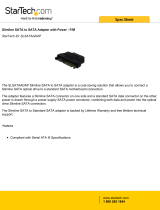
The Intel Server Chassis SR1450 is shown in the following drawing.
TP01584
Figure 1. Intel
®
Server Chassis SR1450

Server Chassis Features
Intel® Server Chassis SR1450 User Guide 15
Table 1 summarizes the major features of the server chassis.
4
Table 1. Server Chassis Features
Feature Description
Dimensions
1.703 inches high
16.930 inches wide
27.480 inches deep (including power receptacles)
35 pounds (max chassis weight)
Hard Drives (dependent
on option selected)
Up to three hot-swap SATA or hot-swap SCSI drives
Peripherals (dependent
on option selected)
Slimline bay for CD-ROM, DVD-ROM drive, or slimline floppy drive
Kit to convert one hard drive bay into a floppy drive bay (optional accessory)
PCI riser card (configurations depend on accessories used)
Control Panel (dependent
on option selected)
Standard Control Panel:
Intel
®
Local Control Panel (requires installation of the optional Intel
®
Management
Module – Advanced or Intel
®
Management Module – Professional)
5
LEDs and displays
(dependent on option
selected)
With Standard Control Panel:
NIC1 Activity
NIC2 Activity
Power / Sleep
System Status
System Identification
Hard Drive Activity
With Intel® Local Control Panel:
NIC1 Activity
NIC2 Activity
Power / Sleep
System Status
System Identification
Hard Drive Activity
LCD Display
USB (dependent on
option selected)
One front panel USB port with Standard Control Panel
Two front panel USB ports with Intel
®
Local Control Panel
Two back panel USB ports
Continued
4
Before purchasing any component noted as either “optional,” or “dependent on option selected,” refer to
your server board documentation to determine which option(s) are supported with your server board.
5
Use of the Local Control Panel requires conversion of one hard drive bay.

Server Chassis Features
16
Table 1. Server Chassis Features (continued)
Power Supply
One hot-swap 520W power supply module
One plus one hot-swap redundant 520W power supply (optional accessory)
System Security
Lockable front bezel (optional accessory)
Chassis intrusion switch
Lock attach point for Kensington* style lock
Fans
• Four 40x40x56mm dual-rotor system fans
• One 40x40x28mm single rotor system fan
• Two 40x40x56mm dual-rotor power supply fans (dedicated to power supply
cooling)
Video
One rear panel video port

Server Chassis Features
Intel® Server Chassis SR1450 User Guide 17
Component Identification
Internal Components
The diagram below shows the server chassis with a server board installed into it.
TP01585
C
A
L
M
K
J
I
H
D
B
G
E
F
A. Single system PCI fan H. System fan module
B. Power supply fan modules I. SATA or SCSI backplane
C. Power supply air duct J. Control panel (Standard Control Panel shown)
D. Rear power supply module K. Drive bay area (drives not included)
E. PCI Riser assembly L. CD/DVD – ROM/Floppy drive bay
F. Server board M. Front power supply module
G. Processor air duct.
Not shown: rack handles, optional front bezel,
chassis cover
Figure 2. Internal Component Locations

Server Chassis Features
18
Standard Control Panel
The diagram below shows the features available on the Standard Control Panel. The Standard
Control Panel is one of two required front panel options that can be selected. The other option is the
Intel® Local Control Panel. For instructions on installing the Standard Control Panel, see
“Replacing the Standard Control Panel.”
TP01586
A CB
D
F G KIH J
E
Callout Feature Function
A USB 2.0 port Allows you to attach a USB component to the front of the chassis.
B NMI button Puts the server in a halt-state for diagnostic purposes.
C Reset button Reboots and initializes the system.
D Hard disk drive
activity LED
Random blinking green light indicates hard disk drive activity (SCSI
or SATA).
No light indicates no hard disk drive activity.
E
F
NIC 1 activity LED
NIC 2 activity LED
Blinking green light indicates network activity.
Continuous green light indicates a link between the system and the
network to which it is connected.
G System Status LED Solid green indicates normal operation
Blinking green indicates degraded performance
Solid amber indicates a critical or non-recoverable condition
Blinking amber indicates a non-critical condition
No light indicates POST is running or the system is off
H Power/Sleep button Toggles the system power on/off. Sleep button for ACPI-compatible
operating systems.
I Power/Sleep LED Continuous green light indicates the system has power applied to it.
Blinking green indicates the system is in S1 sleep state
No light indicates the power is off / is in ACPI S4 or S5 state.
J System identification
button
Toggles the front panel ID LED and the server board ID LED on and
off. The server board LED is visible from the rear of the chassis and
allows you to locate the server from the rear of a rack of systems.
K System Identification
LED
Solid or blinking blue indicates system identification is active
No light indicates system identification is not activated
Figure 3. Standard Control Panel Features

Server Chassis Features
Intel® Server Chassis SR1450 User Guide 19
Intel
®
Local Control Panel
The diagram below shows the features available on the Intel
®
Local Control Panel. The Intel Local
Control Panel is one of two required front panel options that can be selected. The other option is the
Standard Control Panel. For instructions on installing the Standard Control Panel, see “Replacing
the Intel® Local Control Panel”.
✏ NOTE
This control panel requires the installation of the Intel
®
Management Module,
Professional or Advance Edition.
TP01587
M L K J HIN G
C
D
E
F
BA
Callout Feature Function
A USB 2.0 port Allows you to attach a USB component to the front of the chassis.
B LCD display Screen on which system information is displayed.
C Menu control button,
scroll up
Scroll up one option at a time.
D Menu control button,
scroll down
Scroll down one option at a time.
E Menu control button,
scroll left
Move to the previous option.
F Menu control button,
enter
Enter/select the option.
G System Identification
LED
Solid or blinking blue indicates system identification is active.
No light indicates system identification is not activated.
H Power/Sleep LED Continuous green light indicates the system has power applied to it.
Blinking green indicates the system is in S1 sleep state.
No light indicates the power is off / is in ACPI S4 or S5 state.
I Power/Sleep button Toggles the system power on/off. Sleep button for ACPI-compatible
operating systems.
Continued

Server Chassis Features
20
Callout Feature Function
J System Status LED Solid green indicates normal operation.
Blinking green indicates degraded performance.
Solid amber indicates a critical or non-recoverable condition.
Blinking amber indicates a non-critical condition.
No light indicates POST is running or the system is off.
K
L
NIC 2 activity LED
NIC 1 activity LED
Continuous green light indicates a link between the system and the
network to which it is connected.
Blinking green light indicates network activity.
M Hard disk drive
activity LED
Random blinking green light indicates hard disk drive activity (SCSI
or SATA).
No light indicates no hard disk drive activity is taking place.
N Reset button Reboots and initializes the system.
Figure 4. Intel
®
Local Control Panel Features
Back Panel Features
TP01588
A
B
I
H
G K
L
M O
J
C ED
F
N
A. Mouse port I. NIC1
B. Low-profile add-in card bracket J. NIC2
C. Full-height add-in card bracket K. Video
D. AC power receptacle (front power supply) L. USB1
E. AC power receptacle (rear power supply) M. USB0
F. Rear power supply module
N. IMM Advanced Dedicated NIC
Knock Out
G. Keyboard port O. SCSI Channel B
H. Serial Port B
Figure 5. Chassis Back
✏ NOTE
The AC power supply receptacles are linked to separate power supply
modules.
/