Warmup Inslab Cable – INSLAB Installation guide
- Category
- Space heaters
- Type
- Installation guide
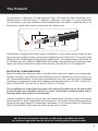
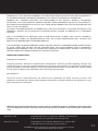
Warmup Inslab Cable – INSLAB is the world's best-selling electric floor heating brand designed for installation within a slab of at least 2” (50mm) in thickness with at least 11/8” (30mm) of slab above the heating wire. It is a twin conductor surrounded by a ground shield for electrical protection and comes with a 16-foot power supply lead wire for connection to a thermostat. The product is designed for 240V supply installations and produces between 10 to 20 Watts per sqft (100W to 200W/SQM) of heating, depending on the spacing of the cable.
Warmup Inslab Cable – INSLAB is the world's best-selling electric floor heating brand designed for installation within a slab of at least 2” (50mm) in thickness with at least 11/8” (30mm) of slab above the heating wire. It is a twin conductor surrounded by a ground shield for electrical protection and comes with a 16-foot power supply lead wire for connection to a thermostat. The product is designed for 240V supply installations and produces between 10 to 20 Watts per sqft (100W to 200W/SQM) of heating, depending on the spacing of the cable.


-
 1
1
-
 2
2
-
 3
3
-
 4
4
-
 5
5
-
 6
6
-
 7
7
-
 8
8
-
 9
9
-
 10
10
-
 11
11
-
 12
12


Warmup Inslab Cable – INSLAB Installation guide
- Category
- Space heaters
- Type
- Installation guide
Warmup Inslab Cable – INSLAB is the world's best-selling electric floor heating brand designed for installation within a slab of at least 2” (50mm) in thickness with at least 11/8” (30mm) of slab above the heating wire. It is a twin conductor surrounded by a ground shield for electrical protection and comes with a 16-foot power supply lead wire for connection to a thermostat. The product is designed for 240V supply installations and produces between 10 to 20 Watts per sqft (100W to 200W/SQM) of heating, depending on the spacing of the cable.
Ask a question and I''ll find the answer in the document
Finding information in a document is now easier with AI
Related papers
-
Warmup Non-Jacketed Self-Regulating Cable Installation guide
-
-
-
-
-
Warmup WHS-X-EDGE50 Operating instructions
-
-
-
Warmup DWM-120-1540 Operating instructions
-
Other documents
-
WarmlyYours Slab Heat TH115, TH114 and a Relay Product information
-
-
Danfoss BasicRail Installation guide
-
 Ouellet OWC-R Series User manual
-
COLDBUSTER In Slab Heater Kit Installation guide
-
COLDBUSTER Under Tile Installation guide
-
COLDBUSTER Under Carpet Floor Heater Kit Installation guide
-
tekmar Programmable Thermostat 510 Installation guide
-
Reznor EFMA Installation guide
-
