Page is loading ...

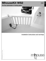
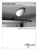
MhouseKit GD1-GD5-GD10
For the automation of a sectional or overhead door.
ISTGD10-GBR02.4865 - Rev.00 - 01-05-2010
Installation instructions and warnings


3
WARNINGS
STEP 1 4
PRODUCT DESCRIPTION
STEP 2 5
2.1 - Applications 5
2.2 - Description of the automation 5
2.3 - Description of devices 5
- 2.3.1 - GD1K, GD5K and GD10K Electromechanical Gearmotor 6
- 2.3.2 - PH1 photocells (optional) 6
- 2.3.3 - KS1 key-operated selector switch (optional) 7
- 2.3.4 -
FL1 flashing light with incorporated aerial (optional)
7
- 2.3.5 - TX4 radio transmitter 7
INSTALLATION
STEP 3 7
3.1 - Preliminary checks 7
- 3.1.1 - Operating limits 9
- 3.1.2 - Tools and Materials 9
- 3.1.3 - List of cables 9
3.2 - Preparing the Electrical System 10
- 3.2.1 - Connection to the Electrical Mains 10
3.3 - Installation of the Various Devices 10
- 3.3.1 - Assembly of the guide supplied with GD1 and GD5 10
- 3.3.2 - Assembly of the guide supplied with GD10 11
- 3.3.3 - Fixing of the gearmotor to the guide 12
- 3.3.4 - Fixing of the gearmotor to the ceiling 12
- 3.3.5 - Photocells (optional) 14
- 3.3.6 - KS1 key-operated selector switch (optional) 14
- 3.3.7 - FL1 flashing light (optional) 15
- 3.3.8 - Electrical connections to the control unit 16
3.4 - Power Supply Connection 16
3.5 - Initial checks 16
- 3.5.1 -
Recognition of Connected Devices
17
- 3.5.2 - Learning of the door's open and closed positions 17
- 3.5.3 - Testing the radio transmitter 17
3.6 - Regulations 18
- 3.6.1 - Selecting door speed 18
- 3.6.2 - Selecting the type of operating cycle 18
3.7 - Testing and Commissioning 18
- 3.7.1 - Testing 18
- 3.7.2 - Commissioning 19
MAINTENANCE
STEP 4 19
PRODUCT DISPOSAL 19
ADDITIONAL INFORMATION
STEP 5 20
5.1 - Advanced Adjustments 20
- 5.1.1 - Adjusting the Parameters with the Radio Transmitter 20
- 5.1.2 - Checking the Adjustments with the Radio Transmitter 20
5.2 - Optional Accessories 20
5.3 - Adding or Removing Devices 21
- 5.3.1 - ECSBus 21
- 5.3.2 - STOP Input 21
- 5.3.3 - Recognition of Other Devices 21
- 5.3.4 - Addition of Optional Photocells 21
5.4 - Memorization of Radio Transmitters 22
- 5.4.1 - Memorization Mode 1 22
- 5.4.2 - Memorization Mode 2 22
- 5.4.3 - Remote memorization 23
- 5.4.4 - Deleting a Radio Transmitter 23
- 5.4.5 - Deleting all the Radio Transmitters 23
5.5 - Troubleshooting 23
5.6 - Diagnostics and Signals 24
- 5.6.1 - Photocells 24
- 5.6.2 - Flashing and courtesy lights 24
- 5.6.3 - Control Unit 25
TECHNICAL CHARACTERISTICS
STEP 6 26
TECHNICAL DOCUMENTATION
STEP 7 I
7.1 - Operating guide I
- 7.1.1 - Safety regulations I
- 7.1.2 - Door Control I
- 7.1.3 - Maintenance Operations to Be Performed by the User I
- 7.1.4 - Replacing the Remote Control Battery II
- 7.1.5 - Lamp replacement II
CE Declaration of Conformity of GD Components III
CE Declaration of Conformity of Power Operated Sectional or Overhead Door IV
CONTENTS

4
WARNINGS
• In the event that liquid substances have penetrated inside the
automation devices, immediately disconnect the power supply and
contact the MHOUSE customer service department. The use of GD
in these conditions can be dangerous.
•Keep all components of GD away from heat sources and open
flames; these could damage the components and cause malfunc-
tions, fire or dangerous situations.
• Connect the gearmotor only to a power supply line equipped with
safety grounding system.
• All operations requiring the opening of the protection shell of GD
device must be performed with the gearmotor disconnected from
the power supply; if the disconnection device is not identifiable, post
the following sign on it: “WARNING: MAINTENANCE WORK IN
PROGRESS”.
• In the event that any automatic switches or fuses are tripped, you
must identify the failure and eliminate it before you reset them.
• If a failure occurs that cannot be solved using the information pro-
vided in this manual, refer to the MHOUSE customer service depart-
ment.
Particular warnings concerning the suitable use of this product in relation
to the “Machine Directive” 2006/42/CE:
• This product comes onto the market as a “machine component” and is
therefore manufactured to be integrated to a machine or assembled with
other machines in order to create “a machine”, under the directive
2006/42/CE, only in combination with other components and in the man-
ner described in the present instructions manual. As specified in the direc-
tive 2006/42/CE the use of this product is not admitted until the manufac-
turer of the machine on which this product is mounted has identified and
declared it as conforming to the directive 2006/42/CE.
Particular warnings concerning the suitable use of this product in relation
to the “Low Voltage” Directive 2006/95/CE:
• This product responds to the provisions foreseen by the “Low Voltage”
Directive if used in the configurations foreseen in this instructions manual
and in combination with the articles present in the Mhouse S.r.l. product
catalogue. If the product is not used in configurations or is used with oth-
er products that have not been foreseen, the requirements may not be
guaranteed; the use of the product is prohibited in these situations until
the correspondence to the requirements foreseen by the directive have
been verified by those performing the installation.
Particular warnings concerning the suitable use of this product in relation
to the “Electromagnetic Compatibility” Directive 2004/108/CE:
• This product has been subjected to tests regarding the electromagnetic
compatibility in the most critical of use conditions, in the configurations
foreseen in this instructions manual and in combination with articles pres-
ent in the Mhouse S.r.l. product catalogue. The electromagnetic compati-
bility may not be guaranteed if used in configurations or with other prod-
ucts that have not been foreseen; the use of the product is prohibited in
these situations until the correspondence to the requirements foreseen by
the directive have been verified by those performing the installation.
STEP 1
Important installer and user safety instructions
• If this is the first time that you install a GD sectional or overhead door
automation system we recommend that you dedicate some of your time
to reading this manual. You should read it before you start installing the
system, so you don’t have to rush to finish the work.
Keep all the components of the GD system handy so that you can read,
check and verify all the information contained in this manual. However, do
not carry out the adjustment and memorization stages otherwise, during
the actual installation of the products, you will have to deal with settings
that differ from the original factory ones.
• When reading this manual, pay special attention to the sections marked
by the following symbol:
these sections are particularly important for safety.
• Store this manual safely for future use.
• This manual, as well as the design and manufacture of the devices that
make up GD, comply fully with the standards and regulations in force.
• Considering the hazards that may exist during the installation and opera-
tion of GD, it is necessary that also the installation be carried out in strict
compliance with current legislation, standards and regulations, particularly:
• This manual contains important information regarding personal
safety; before you start installing the components, it is important that
you read and understand all the information contained herein. Do not
proceed with the installation if you have doubts of any sort; if neces-
sary, refer to the MHOUSE customer service department for clarifica-
tions.
• Follow all installation instructions
• Before you start with the installation, make sure that each single
GD device is suitable for the intended automation purposes; pay
special attention to the data provided in chapter 6 “Technical Char-
acteristics”. If even a single device is not suitable for the intended
application, do not proceed with the installation.
• Before you start with the installation, check whether additional
devices or materials are needed to complete the automation with GD
based on the specific application requirements.
• The GD automation system must not be installed outdoors
• The GD automation system must not be used until the automation
has been commissioned as described in paragraph 3.7.2 “Commis-
sioning”.
• The GD automation system cannot be considered as a suitable
intrusion protection system. If you require efficient protection you
need to integrate GD with other devices.
• The packing materials for GD must be disposed of in compliance
with local regulations.
• Do not make modifications to any components unless provided for
in this manual. This type of operations will only cause malfunctions.
MHOUSE disclaims any liability for damage resulting from modified
products.
• Components must never be immersed in water or other liquids.
Also during installation, do not allow liquids to enter the gearmotor
or other open devices.

5
PRODUCT DESCRIPTION
STEP 2
2.1 – APPLICATIONS
GD is a set of components designed for the automation of sectional or
overhead doors in residential applications.
Any applications other than those described above or under different
conditions from those specified in this manual are forbidden.
GD operates with electric power. In the event of a power failure, the gearmo-
tor can be released using a suitable cord in order to move the door manually.
As an alternative, the optional accessory can be used on the GD10 mod-
el: PR1 buffer battery.
2.3 – DESCRIPTION OF DEVICES
GD1, GD5 and GD10 can be made-up of the devices shown in Fig. 2
make immediately sure that they correspond to the contents of the pac-
kage and verify the integrity of the devices.
1
A
B
E
D
C
Note: to adapt GD1, GD5 and GD10 to local regulations, the contents of
the package may vary; an exact list of the contents is shown on the outsi-
de of the package under the “Mhousekit GD1 and GD5 contains” and
“Mhousekit GD10 contains” heading.
Gearmotor type
Maximum torque (corresponding to the maximum force)
Max. No. of ECSBus units
Emergency power supply
Guide length
GD1
10.8Nm (600N)
1
No
3x1m
TABLE 1 - comparison of main features of the GD gearmotor
Reference
A
B
C
D
E
F
G
H
I
GD1 and GD5
1 GD1K or GD5K electromechanical gearmotor with incorporated
control unit.
1 3-metre guide with pre-assembled belt.
2 coupling profiles
2 ceiling-mounted brackets
Miscellaneous small parts: screws, washers, etc. see tables
1, 2, 3 and 4 (*).
1 TX4 radio transmitter.
PH1 pair of wall-mounted photocells
KS1 key-operated selector switch
FL1 flashing light with incorporated aerial.
GD10
1 GD10K electromechanical gearmotor with incorporated con -
trol unit.
1 4-metre guide with pre-assembled belt.
3 coupling profiles
4 ceiling-mounted brackets
Miscellaneous small parts: screws, washers, etc. see tables 1, 2,
3 and 4 (*).
1 TX4 radio transmitter.
PH1 pair of wall-mounted photocells
KS1 key-operated selector switch
FL1 flashing light with incorporated aerial.
TABLE 2 - Component and accessories list
GD5
10.4Nm (800N)
6
con PR1
3x1m
GD10
18Nm (1000N)
6
con PR1
4x1m
2.2 – DESCRIPTION OF THE AUTOMATION
To clarify a few terms and aspects of a sectional or up-and-over door
automation system: In Figure 1 we provide an example of a typical GD1,
GD5 and GD10 application:
A) FL1 flashing light with incorporated aerial (optional)
B) KS1 key-operated selector switch (optional)
C) Pair of PH1 photocells (optional)
D) Mechanical stops
E) GD1K, GD5K and GD10K gearmotors
* The screws required for mounting GD1, GD5 and GD10 are not supplied as they depend on the type of material and its thickness.

6
2.3.1 – GD1K, GD5K and GD10K Electromechanical Gearmotor
GD1K, GD5K and GD10K are electromechanical gearmotors made up of
a 24Vdc motor. It features a mechanical release mechanism with cord that
allows you to move the door manually in the event of a power failure. The
gearmotor is fixed to the ceiling with the relative mounting brackets. The
PR1 buffer battery can be used on the GD5 and GD10 version, which
allows some manoeuvres in the absence of the mains power supply.
The control unit actuates the gearmotors and provides for the control
of the supply of the different components; it features an electronic
board with incorporated radio receiver.
The control unit can actuate the gearmotor with two speeds: “slow” and
“fast”.
The yellow button [C] allows the door to be controlled during testing. The
same key will also be operated during daily use, through the incorporated
orange button [D].
To facilitate the electrical connections there are separate terminals for
each device [A], which are removable and colour-coded based on the
function performed. Next to each input terminal there is a LED that signals
its status.
The connection to the power supply is very easy: just insert the plug in a
power outlet.
2
ab cd
ef gh
i
TABLE 3
List of small parts
M6 self-tapping nuts
M6x14 screws
6,3x38 tcei screws
GD10K
4 pcs
4 pcs
4 pcs
3
A
TABLE 4
List of small parts for PH1
HI LO 4X9,5 screws
3,5X25 self-tapping screw
s 5 c nylon screw anchor
Q.ty
4 pcs
4 pcs
4 pcs
4
2.3.2 – PH0 photocells (optional)
The pair of PH1 wall-mounted photocells, once they are connected to the
control unit, enables the detection of obstacles found on the optical axis
between the transmitter (TX) and the receiver (RX).
GD1K
2 pcs
2 pcs
4 pcs
GD5K
2 pcs
2 pcs
4 pcs
D
C
B

7
2.3.3 – KS1 key-operated selector switch (optional)
The KS1 key-operated two-position selector switch enables door control
without using the radio transmitter. It is equipped with internal light for
locating in the dark.
There are two commands, which depend on the direction of rotation of
the key: “OPEN” and “STOP”; then the key, which is spring loaded,
returns to the centre position.
TABLE 5
List of small parts for KS1
HI LO 4X9.5 screw
3.5X25 self-tapping screw
s 5 c nylon screw anchor
Q.ty
2 pcs
4 pcs
4 pcs
2.3.4 – FL1 flashing light with incorporated aerial (optional)
The flashing light is controlled by the control unit and signals danger when
the door is moving. Inside the flashing light there is also the aerial for the
radio receiver.
TABLE 6
List of small parts for FL1
4.2X32 self-tapping screw
s 6 c nylon screw anchor
Q.ty
4 pcs
4 pcs
2.3.5 – TX4 radio transmitter
The radio transmitter is used for the remote control of the door opening
and closing manoeuvres. It features four buttons that can all be used for
the 4 types of command to a single automation unit, or to control up to 4
different automation units.
The transmission of the command is confirmed by the LED [A]; an eyelet
[B] allows them to be hung on a keyring.
INSTALLATION
STEP 3
The installation must be carried out by qualified and skilled per-
sonnel in compliance with the directions provided in chapter 1
“WARNINGS”.
3.1 – PRELIMINARY CHECKS
The GD1, GD5 and GD10 must not be used to power a door that is
not efficient and safe and cannot solve defects resulting from incor-
rect installation or poor maintenance of the door itself.
WARNING: incorrect installation could cause serious damage.
Before proceeding with the installation you must:
• Make sure that the door movement does not hinder roads or public
footpaths.
• After the motor has been installed, remove unnecessary cables or
chains and turn off any unneeded equipment
• Make sure that the weight and dimensions of the door fall within
the specified operating limits (Chapter 3.1.1). If they do not, GD can-
not be used.
• Make sure that the structure of the door is suitable for automation
and in compliance with regulations in force.
• Make sure that there are no points of greater friction in the opening
or closing travel of the door.
• Make sure that the mechanical structure of the door is sturdy
enough and that there is no risk of derailing out of the guide.
• Make sure that the door is well balanced: it must not move by itself
when it is placed in any position.
• Make sure that the installation area is compatible with the size of
the gearmotor and that it is safe and easy to release it.
• Make sure that the mounting positions of the various devices are
protected from impacts and that the mounting surfaces are suffi-
ciently sturdy.
• Make sure that the mounting surfaces of the photocells are flat and
that they enable the proper alignment between TX and RX.
• Pay attention in particular to the methods for securing the head of
the guide and the brackets to the ceiling. The head of the guide will
have to bear all the strain of opening and closing the door; the ceil-
ing-mounted brackets will have to bear all the weight of GD. In both
5
6
7
B
A

8
cases, the wear and deformations that may occur in time must be
taken into consideration.
• Make sure that the minimum and maximum clearances specified in
fig. 8 are observed.
• The gearmotor should be mounted so that it coincides with the
centre of the door, or is slightly off-centre, e.g. in order to mount the
OSCILLATING ARM next to the handle (Figure 9).
• Make sure that, in the position corresponding to the door, or slight-
ly to the side, (see positions “A” and “B”) the conditions are suitable
for mounting the head of the guide; in particular, the material should
be sufficiently sturdy and compact.
Make sure that GD can be mounted on the ceiling along position “C”
using the mounting brackets.
If the door to be automated is an up-and-over type door with springs
or counterweights, it will be necessary to install an GA1 OSCILLAT-
ING ARM, which must be mounted next to the handle (Figure 9).
• Make sure that distance [E] in Figure 10, i.e. the minimum distance
between the upper side of the guide and the maximum point
reached by the upper edge of the door, is no shorter than 65 mm and
no longer than 100 mm, otherwise GD cannot be installed.
If the door closes a room that has no other means of access, we rec-
ommend installation of the GU1 EXTERNAL RELEASE KIT, otherwise
a simple power failure will prevent access to the room (figure 11).
Otherwise a fault or, for the GD1 version with buffer batteries, a sim-
ple power failure could prevent access to the room.
Note: the oscillating arm and external release kit are supplied with
the related assembly instructions.
8
C
2970 mm D 420 mm
B 0÷400 mm
A 40÷400 mm
280 mm280 mm
9
10
B
0÷400 mm
E 65÷100 mm
11
EXTERNAL MANUAL RELEASE
B
A
E
C
D
2) Fit the steel cable
[C] Sheath
[D] Steel cable
[E] Clamp
1) Fit the lever
[A] Lever
[B] Black screw

9
3.1.2 – Tools and Materials
Make sure you have all the tools and materials needed to install the system; make sure that they are in good condition and serviceable
according to current safety standards. See examples in figure 12.
12
3.1.1 – Operating limits
Chapter 6 “Technical Characteristics” provides the fundamental data
needed to determine whether all the GD1, GD5 and GD10 components
are suitable for the intended application.
In general the GD1, GD5 and GD10 are suitable for the automation of sec-
tional and up-and-over doors for residential applications having the values
shown in the table.
The shape of the door and the climatic conditions (e.g. presence of strong
wind) may reduce this maximum limit. In this case it is necessary to
measure the torque needed to move the door under the worst conditions,
and to compare it to the data provided in the technical characteristics
chart for the GD gearmotor.
TABLE 7
Height
2.4m
2.4m
3.4m
SECTIONAL doorModel Maximum power
GD1
GD5
GD10
600N
800N
1000N
Width
4.4m
5.2m
5.2m
Height
2.2m
2.2m
3.2m
OVERHEAD door,
non-protruding
(with accessory GA1)
Width
4.2m
5m
5m
Height
2.8m
2.8m
3.5m
OVERHEAD door
protruding (with GA1)
or with springs (without GA1)
Width
4.2m
5m
5m
13
E
D
B
A
C
C
3.1.3 – List of cables
The cables required for the installation of GD may vary depending on the type and quantity of devices to be installed; figure 13 shows the cables nee-
ded for a typical installation; no cable is supplied with GD.

10
Note 1 – For the ECSbus, STOP and OPEN cables, there are no special contraindications to the use of a single cable that groups together multi-
ple connections; for example, the STOP and OPEN inputs can be connected to the KS1 selector switch using a single 4x0,5mm
2
cable.
WARNING! – the cables used must be suitable for the type of installation; for example, an H03VV-F type cable is recommended for indo-
or applications.
Table 8: List of cables
Connection
[A] STOP input
[B] OPEN input
[C] ECSBus input/output
[D] FLASH light output
[E] Radio aerial
Maximum length allowed
20 m (note 1)
20 m (note 1)
20 m (note 1)
20 m
20 m (recommended less than 5m)
Cable type
2 x 0,25 mm
2
cable
2 x 0,25 mm
2
cable
TX 2 x 0,25 mm
2
cable
2 x 0,25 mm
2
cable
RG58 type shielded cable
3.2 – PREPARING THE ELECTRICAL SYSTEM
With the exception of the plug and the power cable, the rest of the system
uses extra-low voltage (approx. 24V); the wiring can therefore be done by
personnel that is not properly qualified, provided that all the instructions in
this manual are carefully observed.
After selecting the position of the various devices (refer to figure 12) you
can start preparing the conduits for the electrical cables connecting the
devices to the control unit.
The shock-resistant conduits are designed to protect the electrical cables
and prevent accidental breakage.
Install any fixed control close to the door but away from moving parts and
at a height of 1.5m.
3.2.1 – Connection to the Electrical Mains
Although the connection of GD to the electrical mains is beyond the
scope of this manual, we wish to remind you that:
• The power supply line must be laid and connected by a qualified
professional electrician.
• Have a suitably protected 16A “schuko” outlet installed, where you
can plug in GD.
• Make sure that the power supply cable does not hang over moving
parts or hazardous areas
• The electric line must be grounded and protected against short cir-
cuits; a bipolar disconnection device must also be present with con-
tact separation of at least 3 mm, which allows the power supply to
be disconnected during the installation and maintenance of the GD.
3.3 – INSTALLATION OF THE VARIOUS DEVICES
Depending on the model, the installation of the GD is comprised of the fol-
lowing parts:
- Assembly of the guide supplied with GD1 and GD5 (see paragraph
3.3.1)
- Assembly of the guide supplied with GD10 (see paragraph 3.3.2)
- Fixing of the gearmotor to the guide (see paragraph 3.3.3)
- Fixing of the gearmotor to the ceiling (see paragraph 3.3.4)
3.3.1 – GD1 and GD5 guide assembly
The guide that is supplied with GD1, GD5 and GD10 must be assembled
as follows:
1. Slacken the adjustment screw of the belt tensioner device before
assembling the guide, as in figure 14.
2. Remove the belt from the three pieces that make up the guide
(excluding the part next to the pulley) and place them to one side.
3. With the aid of a hammer, assemble the three pieces of the guide
engaging them into the connection brackets (A) with force, as in fig-
ures 15.
Important – the guides must slide into the brackets until they click into
position.
4. Carefully reposition the belt into the guide making sure that it is not
twisted.
5. Connect the head (B) with force into the guide, as in figure 16.
6. Finally, tension the belt with the adjustment screw (D) of the belt ten-
sioner device, as in figure 16a.
Warning - the gearmotor could break if the belt is too taut and if it is
too slack, it could cause unpleasant noise.
14 15 16a
16
B
A
D

11
5
With the aid of a hammer, assemble the three pieces of the guide engaging
them into the connection brackets (F) with force, as in figures 22 and 22a.
Important – the guides must slide into the brackets until they click into
position.
6 Return the belt tensioner device and carriage to the initial position.
Assemble the guide head section [A], as shown in figure 23. This requires
a certain force; if necessary use a rubber mallet.
7 Insert the spring, washer and M8 nut [D], in the screw of the belt ten-
sioner device, as shown in figure 24.
8 Tension the belt by means of the M8 nut [D] (figure 25) until it is suffi-
ciently taut.
4m version:
If the height of the door to be automated is greater than 2.5m assemble
the guide as follows:
1 Loosen the M8 nut [D] completely, as shown in figure 26.
2 Slide the belt tensioner device to mid-stroke [E], as shown in figure 27,
and remove the carriage completely.
3.3.2 – Assembly of the guide supplied with GD10
The guide is made up of four 1 m long profiles, which permit 2 versions to
be made:
3m version:
If the height of the door to be automated is equal to or less than 2.5 m
assemble the guide as follows:
1 Cut the free end of the belt to obtain a length of exactly 2 metres, as
shown in figure 17.
2 Loosen the M8 nut [D] completely, as shown in figure 18.
3 Slide the belt tensioner device to mid-stroke [E], as shown in figure 19,
and remove the carriage completely.
4 Pass the free end of the belt through the head section, as shown in fig-
ure 20, and secure to the carriage by means of the screws and washers
present, as shown in figure 21. Take care when positioning the belt; the
teeth must be facing inwards, and it must be straight without twists.
17
18
D
19
E
20
21
25
D
26
D
23
A
24
D
22
22a

12
3.3.3 – Fixing of the gearmotor to the guide
1 Couple the gearmotor’s shaft extension with the head of the guide [A],
then secure them using the four M6.3x45 screws [F].
The gearmotor can be rotated in three different positions.
3.3.4 – Fixing of the gearmotor to the ceiling
1 Observing the A, B and C positions shown in Figure 8, mark the 2 fas-
tening points for the guide’s front bracket in the centre of the garage door
(or slightly off-centre - Figure 11).
Depending on the type of material, the front bracket can be fastened
using rivets, anchors or screws (Figure 36). If positions A, B, and C (figure
8) allow it, the bracket can be fastened directly to the ceiling.
34
A
F
7 Tension the belt by means of the M8 nut [D] (figure 33) until it is suffi-
ciently taut.
3 Pass the free end of the belt through the head section, as shown in fig-
ure 28, and secure to the carriage by means of the screws and washers
present, as shown in figure 29. Take care when positioning the belt; the
teeth must be facing inwards, and must be straight without twists.
4 With the aid of a hammer, assemble the four pieces of the guide into the
three connection brackets (F), as in figures 30.
Important - the guides must slide into the brackets until they click
into position.
5 Return the belt tensioner device and carriage to the initial position.
Assemble the guide head section [A], as shown in figure 31. This requires
a certain force; if necessary use a rubber mallet.
6 Insert the spring, washer and M8 nut [D], in the screw of the belt ten-
sioner device, as shown in figure 32.
28
35
36
27
E
29
33
D
31
A
30
F
32
D

13
7 With the door closed, pull the cord and release the carriage [L] from the
guide.
8 Slide the carriage until the door mounted bracket [N] shown in Figure 42
is positioned on the upper edge of the door, exactly perpendicular to the
guide [M]. Next, secure the door mounted bracket [N] with screws or riv-
ets. Use screws or rivets that are suitable for the door material, making
sure that they are capable of bearing all the strain resulting from opening
and closing the door.
9 Loosen the screws in the two mechanical stops, then place the front
mechanical stop [O] before the carriage (Figure 43).
Push the carriage hard in the closing direction and, in the reached posi-
tion, tighten the screw firmly [P].
10 Open the door manually to the desired open position, then place the
rear mechanical stop [Q] near the carriage (Figure 44), and secure it tight-
ing the screw firmly [R].
2 After drilling the holes, leave the head of the gearmotor on the ground,
lift the guide from the front and secure it with two screws, anchors or riv-
ets depending on the type of surface.
3 Secure the mounting brackets [I], using the screws [G] and nuts [H],
and choosing the hole that is closest to the established position B (see
Figure 8).
4 Using a ladder, lift the gearmotor and position the brackets against the
ceiling. Mark the drilling points, then put the gearmotor back on the
ground.
5 Drill the holes as marked; then, using a ladder, lift the gearmotor, posi-
tion the brackets over the holes you have just drilled and fasten them
using screws and anchors suited to the material.
6 Make sure that the guide is perfectly horizontal, then cut the excess of
the brackets using a hacksaw.
37
H
G
Position B
I
38
39
40
44
Q
R
41
42
L
M
N
43
O
P

The terminals can be removed in order to facilitate the operations; make
the connections and then reinsert them.
9 Secure the cover shell [E] using the two screws [F] and a Phillips screw-
driver. Then insert the glass [G], pressing it gently to close it.
3.3.6 – KS1 key-operated selector switch (optional)
1 Determine the position of the selector switch; it must be installed out-
doors, alongside the gate and at a height of approx. 80 cm, so that it can
be used by people of different height.
2 Remove the front glass [A] by prising it out with a slotted tip screwdriv-
er applied to the bottom.
3 To separate the bottom from the shell you need to insert the key and
keep it turned, then pull with a finger inserted in the hole for the passage
of the cables.
4 Breach the four holes at the bottom with a screwdriver; mark the drilling
points using the bottom as reference; make sure that the hole in the bot-
tom matches the outlet for the cables.
11 Make sure that the release cord can be activated at a height less than
1.8m.
3.3.5 – Photocells (optional)
1 Select the position of the two elements that make up the photocell (TX
and RX) observing the following directions:
Position them at a height of 20-25 cm from the ground, on both sides of
the area to be protected and as close as possible to the edge of the door.
With sectional doors, the photocells can be mounted outside, whereas
with up-and-over doors they can only be mounted inside (outside they
would obstruct the movement of the door)
• Point transmitter TX towards receiver RX, with a maximum tolerance of 5°.
• In the selected locations there must be a conduit for threading the
cables.
2 Remove the front glass [A] by prising it out with a slotted tip screwdriv-
er applied to the bottom.
3 Press the lens in order to separate the two shells.
4 Breach two of the four holes [B] at the bottom with a screwdriver.
5 Position the photocell at the point where the conduit arrives; the hole at
the bottom [D] should match the point where the cables come out of the
wall; mark the drilling points using the bottom as reference.
6 Drill the holes in the wall using a hammer drill with a 5 mm bit and insert
the 5 mm screw anchors.
7 Secure the bottom with the screws [C].
8 Connect the electric cable to the appropriate TX and RX terminals. From
an electrical viewpoint, TX and RX must be connected in parallel as shown
in figure 48.
It is not necessary to observe any polarity.
14
45
46
A
B
48
47
B
C
D
B
50
A
51
49
F
G
E

15
4 Breach the four holes for the screws and the hole for the passage of the
cables in the bottom or side, depending on the installation position, using
a screwdriver.
5 Mark the drilling points using the bottom as reference and make sure
that the hole in the bottom matches the outlet for the cables.
6 Drill the holes in the wall using a hammer drill with a 6 mm bit and insert
the 6 mm screw anchors.
7 Secure the bottom with the screws [C].
8 Connect the electrical cables to the appropriate FLASH and “aerial” ter-
minals as shown in figure 58. You do not need to observe any polarity on
the FLASH terminal; however, for the connection of the shielded cable to
the aerial, connect the braid as shown in figure 59. The terminals can be
removed in order to facilitate the operations; make the connections and
then reinsert them (Figure 60).
9 Fit the lamp holder on the base and press it down until it snaps into
position.
10 Slide in the diffuser, pressing the buttons and fitting it on the bottom.
Rotate it in the desired direction then press it down until the two buttons
snap into their seat.
5 Drill the holes in the wall using a hammer drill with a 5 mm bit and insert
the 5 mm screw anchors.
6 Secure the bottom using the four screws [A].
7 Connect the electric cables to the appropriate OPEN and STOP termi-
nals, as shown in figure 53. It is not necessary to observe any polarity. The
terminals can be removed in order to facilitate the operations; make the
connections and then reinsert them.
8 To insert the shell on the bottom you need to turn the key. After you have
inserted it, turn the key back to the centre position.
9 Secure the body [C] using the two screws [D] and a Phillips screwdriv-
er. Finally insert the glass [E], pressing it gently to close it (Figure 54).
3.3.7 – FL1 flashing light (optional)
1 Determine the position of the flashing light: it should be near the door and
easy to see; it can be secured to a horizontal as well as vertical surface.
2 Slide out the diffuser [A] from the bottom by pressing the two buttons
[B].
3 Separate the lamp holder with the aerial from the base.
52
A
53
55
56
A
B
C
C
57
58 59 60
61
54
D
E
C

3.3.8 – Electrical connections to the control unit
1 Open the cover by loosening screw [A] and pushing point [B].
2 Thread the cables through the slit [C].
3 Refer to figure 65 for the electrical extra low voltage connection of the
various devices to the control unit terminals.
• The terminals have the same colour coding as the corresponding
devices; for example, the grey terminal (OPEN) of the control unit must be
connected to the grey terminal (OPEN) of the KS1 selector (optional
accessory).
• For most connections you do not need to observe any polarity; only for
the shielded cable of the aerial incorporated in the FL1 flashing light
(optional accessory). it is necessary to connect the central core and the
shield as shown in figure 65.
• If you are using the flasher’s aerial, remove the piece of wire (connected
to the green terminal at the factory) and connect the RG58-type shielded
braiding.
• The terminals [D] can be removed in order to facilitate the operations as
shown in figure 66; make the connections and then reinsert them.
16
4 When the connections have been completed secure the cables using
suitable clamps.
5 To close the cover, rotate it and push until you hear a click. Tighten
screw [A].
62
A
B
64
63
C
66
D
65
FL1
PH1 PH1 KS1
3.4 – POWER SUPPLY CONNECTION
The connection of the GD control unit to the mains must be ma -
de by a qualified electrician.
To carry out tests, insert the plug for GD in a power outlet; if necessary,
use an extension cord.
3.5 – INITIAL CHECKS
As soon as the control unit is energized, you should check the following:
1 Make sure that the LED [A] flashes regularly, with about one flash per
second.
2 If the system is equipped with the PH1 photocells, make sure that the
SAFE LED [B] shown in figure 69 flashes (on both TX and RX). The type of
flashing is irrelevant, it depends on other factors; what matters is that it is
not always off or always on.
67
68
A
69
B

17
3 If the system is equipped with the KS1 key-operated selector switch,
make sure that the night light [C] is on.
4 If the above conditions are not satisfied, you should immediately switch
off the power supply to the control unit and check the cable connections
more carefully. For more useful information see also chapters 5.5 “Trou-
bleshooting” and 5.6 “Diagnostics and Signals”.
3.5.1 – Recognition of Connected Devices
When you have completed the initial checks, the control unit must recog-
nize the devices connected to it on the “ECSBus” and “STOP” terminals.
1 On the control unit, press the P2 button [C] and hold it down for at least
three seconds, then release the button (Figure 71).
2 Wait a few seconds for the control unit to finish recognizing the devices.
3 When the recognition procedure is completed, the STOP LED [A] must
remain on, while the P2 LED [B] must go off. If the P2 LED flashes it
means that an error has occurred: see paragraph 5.5 “Troubleshooting”.
The connected devices recognition stage can be repeated again at any
time, even after the installation (for example, if an additional photocell is
installed); just repeat the procedure starting from step 1.
3.5.2 – Learning of the door’s open and closed positions
After recognizing the devices, the control unit must recognize the door’s
open and closed positions. During this stage, the travel of the door from
the closing stop to the opening stop is detected.
1 Make sure that the carriage is attached.
2 Press key P3 [A] on the control unit and hold it down for at least three
seconds, then release the key (Figure 72).
70
C
71
A
B
C
72
B
A
• Wait until the control unit has completed the learning stage: closing,
opening and re-closing of the door.
• If any device is triggered during the learning stage, or the P3 key is
pressed, the learning stage will be immediately interrupted. In this case it
must be repeated from the beginning.
• During the learning stage the courtesy light will flash just like the flash-
ing light.
3 If the P3 LED [B] flashes at the end of the learning stage, it means that
there is an error; see paragraph 5.5 “Troubleshooting”.
4 Press the yellow button [C] in figure 73 to execute a complete opening
and closing manoeuvre. During these two manoeuvres the control unit
memorizes the force needed at each point along the travel. It is important
that these two first manoeuvres are not interrupted by any commands.
It is important that these two first manoeuvres are not interrupted.
If the manoeuvres are not completed, repeat the learning procedure start-
ing from step 1.
The position learning stage can be repeated at any time in the future (for
instance, if one of the mechanical stops is moved); just repeat starting
from step 1.
WARNING: if the belt is not tightened properly, during the search
for the positions it may slip on the pinion. If this happens, stop the
leaning procedure by pressing key P3 and stretch the belt by tight-
ening the nut [D]. Then repeat the learning procedure starting from
step 1.
3.5.3 – Testing the radio transmitter
To test the transmitter just press one of its 4 keys, make sure that the red
LED flashes and that the automation carries out the related command.
The command associated to each button depends on how it has been
memorized (see paragraph 5.4 “Memorization of Radio Transmitters”).
The transmitter supplied has already been memorized and when you
press the buttons the following commands are transmitted:
73
C
74
D
Button T1 “OPEN” command
Button T2 “Open partially” command
Button T3 “Open only” command
Button T4 “Close only” command

3.6 – REGULATIONS
3.6.1 – Selecting door speed
The door can be opened and closed at two speeds: “slow” or “fast”.
To switch from one speed to the other press the P2 button [B] momen-
tarily; the corresponding P2 LED [A] will light up or go off; if the LED is off
the speed is “slow”, if the LED is on the speed is “fast”.
18
75
T1
T2
T3
T4
76
B
A
77
B
A
3.6.2 – Selecting the type of operating cycle
The opening and closing of the door can take place according to different
operating cycles:
• single cycle (semiautomatic): the door opens with a command and stays
open until the next command is given, causing it to close.
• complete cycle (automatic closing): the door opens with a command
and then closes automatically after a short time (for the time, see para-
graph 5.1.1 “Adjusting the parameters with the radio transmitter”).
To switch from one operating cycle to the other, press the P3 button [B]
momentarily; the corresponding LED P3 [A] will light up or go off; if the
LED is off the cycle is “single”, if the LED is on the cycle is “complete”.
3.7 – TESTING AND COMMISSIONING
These are the most important operations, designed to guarantee the
maximum safety and reliability of the automation system.
The testing procedure can also be used as a periodic check of the
devices that make up the automation.
The testing and commissioning operations must be performed
by qualified and experienced personnel who must establish what
tests should be conducted based on the risks involved, and verify
the compliance of the system with applicable regulations, legislation
and standards, in particular with all the provisions of EN standard
12445 which establishes the test methods for sectional and up-and-
over door automation systems.
3.7.1 – Testing
1 Make sure that the provisions contained in chapter 1 “WARN-
INGS” have been carefully observed.
2 Using the selector switch (if provided) or the radio transmitter, test the
opening and closing of the door and make sure that the door moves in the
intended direction.
The test should be carried out a number of times to make sure that the
door moves smoothly, that there are no points of excessive friction and
that there are no defects in the assembly or adjustments.
3 Check the proper operation of all the safety devices, one by one (photo-
cells, sensitive edges, etc.). In particular, each time a device is activated
the “ECSBus” LED on the control unit flashes for a longer time, confirming
that the control unit recognizes the event.
4 To check the photocells (if provided) pass a 5 cm diameter, 30 cm long
cylinder on the optical axis, first near TX, then near RX and finally at the
mid-point between them and make sure that in all these cases the device
is triggered, switching from the active to the alarm status and vice-versa;
finally, that it causes the intended action in the control unit, for example
that it causes the reversal of the movement during the closing manoeuvre.
5 The control of the correct obstacle detection is performed with the
700x300x200mm test parallelepiped with 3 black sides and 3 polished
white or mirrored sides, according to the EN 12445 standard.
6 Measure the impact force according to EN standard 12445. If “motor
force” control is used to assist the system for the reduction of the impact
force, try to find the adjustment that gives the best results.
7 Ensure that the entire mechanism is correctly adjusted and that the
automation system inverts the manoeuvre when the door collides with a
50 mm high object on the floor.
78

19
8 Ensure that the automation prevents or blocks the opening manoeuvre
when the door is loaded with a mass of 20 Kg, fixed in the middle of the
doors lower edge.
3.7.2 – Commissioning
The commissioning operations can be performed only after all the
tests have been successfully carried out. Partial commissioning or
implementation of “temporary” conditions are not permitted.
1 Prepare the technical documentation for the automation, which must
include at least: assembly drawing (e.g. figure 1), wiring diagram (e.g. fig-
ure 65), analysis of hazards and solutions adopted, manufacturer’s decla-
ration of conformity of all the devices installed. For GD use Annexe 1 “EC
Declaration of Conformity of the GD components”
2 Post a label on the door providing at least the following data: type of au -
tomation, name and address of manufacturer (person responsible for the
“commissioning”), serial number, year of manufacture and “CE” marking.
3 Fill out the declaration of conformity and deliver it to the owner of the
automation system; for this purpose you can use Annexe 2 “EC Declara-
tion of Conformity”
4 Prepare the operating guide and deliver it to the owner of the automa-
tion system; Annexe 3 “OPERATING GUIDE” can be used as an example.
5 Prepare the maintenance schedule and deliver it to the owner of the
automation system; it must provide directions regarding the maintenance
of all the automation devices.
6 Post a permanent label or sign detailing the operations for the release
and manual manoeuvre (use the figures in Annex 3 “Operating guide”).
7 Before commissioning the automation system inform the owner regard-
ing dangers and hazards that are still existing.
8 Post a permanent label or sign with this image on the door (minimum
height 60 mm) with inscription WARNING - RISK OF CRUSHING.
79
PRODUCT DISPOSAL
Disposal of buffer battery (if present)
Important! – Even if discharged, the batteries may contain pollutant sub-
stances and therefore must NEVER be disposed of in normal waste col-
lection points.
Dispose of according to separate waste collection methods as envisaged
by current local standards.
This product is an integral part of the automation system it controls
and must be disposed of along with it.
As in the case of installation, likewise at the end of product lifetime the dis-
assembly and scrapping operations must be performed by qualified per-
sonnel.
This product is made of various types of material, some of which can be
recycled while others must be scrapped. Seek information on the recycling
and disposal methods envisaged by the local regulations in your area for this
product category.
Important! – Some parts of the product may contain polluting or haz-
ardous substances which, if released to the environment, may cause seri-
ous damage to the environment or to human health.
As indicated by the symbol alongside, disposal of this prod-
uct with domestic waste is strictly prohibited. Separate the
waste into categories for disposal, according to the methods
established by current legislation in your area, or return the
product to the retailer when purchasing a new version.
Important! – Local legislation may impose heavy fines in the event of ille-
gal disposal of this product.
MAINTENANCE
3.7.1 “Testing” and the operations described in paragraph 7.3.3 “Mainte-
nance Operations to Be Performed by the User”.
If other devices are present, follow the directions provided in the corre-
sponding maintenance schedule.
STEP 4
The maintenance operations must be performed in strict compli-
ance with the safety directions provided in this manual and accord-
ing to the applicable legislation and standards.
The devices used for the GD automation system do not require any spe-
cial maintenance. However, periodically make sure (at least once every six
months) that all the devices are perfectly efficient.
To this end, carry out all the tests and checks described in paragraph

20
ADDITIONAL INFORMATION
different values:
1) Pause time: time during which the door remains open (in the automatic
closing mode).
2) Partial opening: partial door opening mode.
3) Motor force: maximum force beyond which the control unit recognizes
an obstacle and reverses the movement.
4) “OPEN” function: sequence of movements associated to each “OPEN”
command.
STEP 5
The following chapters describe different ways of customizing GD to
make it suitable for specific application requirements.
5.1 – ADVANCED ADJUSTMENTS
5.1.1 – Adjusting the Parameters with the Radio Transmitter
The radio transmitter can be used to adjust certain control unit operation
parameters: there are four parameters and each of them can have four
Parameter
Pause time
“OPEN” function
Motor force
“OPEN” function
N°
1°
2°
3°
4°
1°
2°
3°
4°
1°
2°
3°
4°
1°
2°
3°
4°
Action: operation to be performed at point 3 in the adjustment phase
Press button T1 once
Press button T1 twice
Press button T1 three times
Press button T1 four times
Press button T2 once
Press button T2 twice
Press button T2 three times
Press button T2 four times
Press button T3 once
Press button T3 twice
Press button T3 three times
Press button T3 four times
Press button T4 once
Press button T4 twice
Press button T4 three times
Press button T4 four times
TABLE 9
Setting
10s
20s (*)
40s
80s
Opening the door 1/4 of the way
Opening the door half way (*)
Opening the door 3/4 of the way
Opening the door all the way
Low
Medium-low (*)
Medium-high
High
“Open”-“Stop”-“Close”-“Stop”
“Open”-“Stop”-“Close”-“Open” (*)
“Open”-“Close”-“Open”-“Close”
“Open”-“Open”-“Open” (opening only)
The parameter adjustment operation can be performed using a radio
transmitter, provided it is memorized in mode 1 like the one supplied.
If no transmitter memorized in Mode 1 is available, you can memorize one
just for this phase and delete it immediately afterwards (see paragraph
5.4.1 “Mode 1 memorization” and paragraph 5.4.4 “Deleting a radio
transmitter”).
WARNING: when using the transmitter to make adjustments you need to
give the control unit time to recognize the radio command; this means
that the buttons must be pressed and released slowly, held down for at
least one second, then released for one second and so on.
1 Press buttons T1 and T2 on the radio transmitter simultaneously for at
least 5s.
2 Release the two buttons.
3 Within 3 seconds, perform the action described in Table 9 based on the
parameter to be modified.
Example: to set the pause time at 40 s.
1
st
Press buttons T1 and T2 and hold them down for at least 5s
80
T1 T2
2
nd
Release T1 and T2
3
th
Press button T1 three times
All the parameters can be adjusted as required without any contraindica-
tion; only the adjustment of the “motor force” requires special care:
• Do not use high force values to compensate for points of abnormal fric-
tion on the door. Excessive force can compromise the operation of the
safety system or damage the door.
• If the “motor force” control is used to assist the impact force reduction
system, measure the force again after each adjustment in compliance
with EN standard 12445.
• The weather conditions may affect the movement of the door, therefore
periodic re-adjustments may be necessary.
5.1.2 – Checking the Adjustments with the Radio Transmitter
With a radio transmitter memorized in Mode 1 you can check the values
set for each parameter at any time by following the sequence described
below:
1 Press buttons T1 and T2 on the radio transmitter simultaneously for at
least 5s.
2 Release the two buttons.
3 Within 3 seconds, perform the action described in Table 9 based on the
parameter to be checked.
4 Release the button when the flashing light starts flashing
5 Count the flashes and, based on their number, check the corre-
sponding value in table 8.
Example: If the flashing light flashes three times after you have
pressed T1 and T2 for 5s and then button T1, the pause time is set at
40s.
(*) Original factory setting
/