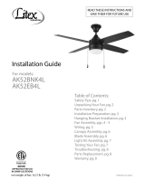
YOUKAIN HDLP-CFJS5206DC User manual

Type
User manual

This manual is also suitable for

Glass lamp cover x1
Blade x3
Downrod and hanging ball Light cover x1
Leaves fork x3
Decorative covers x1
Light Cup x1
Canopy x1
Hanger bracket x1
Remote control x1 Spiral package
Motor x1
25" x1
6" x1
Installation Guide
Balance
pieces
x1
x4
x2
x7
x10
x10
x4
x5
To prevent personal injury and damage,
ensure that the hanging location allows
the blades a clearance of 2.3m
from the floor and 76cm from
any wall or obstruction.
Be sure the outlet box is securely
attached to the building structure and
can support the full weight of the fan.
76cm From
Wall or
Nearest
Obstruction
2.3m
blades to
Floor
This fan can be mounted with a downdrod on a normal or vaulted ceiling.
The hanging length can be extended by a longer downdrod.
Installation Preparation
Downrod Installation
Support Brace
Standard
Mounting
Style
Standard Mounting hangs from the
ceiling by a downrogd
Angled
Mounting
Style
20° Support Brace
Angled Mounting recommended for a
vaulted or angled ceiling
Installation requires these tools:
Screwdriver, flat-head screwdriver, adjustable pliers or wrench, stepladder,
wire cutters, and rated electrical tape.
Preparing the Fan Site
3
Installing the Hanger Bracket
Wood Ceiling
Concrete Ceiling
Please drill φ8mm hole on the concrete ceiling, and insert the bolt.
Align bracket with the hole, then tighten with nut.
4
through clip
Adapter
R clip
yoke set screw
Assembling and Hanging the Fan
Canopy
hanging
ball slot Decorative covers
If you wish to extend the hanging length of your fan, you must remove
the hanging ball from the 6 inch downrod provided to use with
an extended downrod (included) . (If you wish to use the 6 inch downrod,
please proceed to instrucons below.)
To remove hanging ball, loose set screw on hanging ball and remove pin
and clip. Lower hanging ball and remove stop pin. Slide hanging ball
off the original downrod A, and slide it down the longer
downrod B (the top of the downrod should be noted as having
a set screw hole; use this hole when seng the set screw).
Insert stop pin into top of extended downrod and raise hanging ball.
Be sure stop pin aligns with slots on the inside of the hanging ball,
ghten set screw securely.
Tip: To prepare for threading electrical wires through downrod, apply small
piece of electrical tape to the ends of electrical wires-this will keep
the wires together when threading them through the downrod.
Loosen yoke set screws and nut at top of motor housing. Remove pin
and clip from downrod (if you have not already done so). Slide downrod
through canopy.
Tread electrical wires through downrod and pull extra wire slack from
the upper end of the downrod.
Place downrod into the motor housing yoke and ew-insert pin and
clip that were previously removed. Tighten yoke set screws and nut securely.
Lower canopy to motor housing.
electrical
wiring
5
green/yellow stripe
Light Lblue
Neutral N White
Ground
wire
N
L
Input L
Input N
(Black)
(white)
Grey DC motor U
Pink DC motor W
Red DC motor V
Receiver place:
DC:
6
Remote control connection
Remote
control
receiver
12
Canopy
ok
Quick installation:Place a paper pad on each screw and then secure the blade arm to
the blade.
Align the blade holes with the motor screw holes, tighten the screw and secure all
blades.For each blade, the motor rotates an angle to facilitate tool mounting screws.
Note: Tighten blade screws twice.
2 3
Canopy Assembly
1
Blade Assembly
7
raise canopy to hanging bracket,aligning loosened screws in hanging bracket with
slotted holes in canopy.Twist canopy to lock.Re-insert screws and secured all screws
with screwdriver.
Tip:Seek the help of another person to hold the stepladder in place and to lift the fan
up to you once you are set on the ladder.
with hanging bracket secured to the out let box and able to support to fan,you
are now ready to hang your fan. Grab the fan firmly with two hands.Slide downrod
throughopening in hanging bracket and let hanging ball rest on the hanging
bracket.Turnthe hanging ball slot until it lines up with the hanging bracket tab.
Connection
Box
Light cover
The lampshade is paired with the two lamp lines on the junction box, and pay attention to
distinguish the male and the female terminals.
Remove one screw on the junction box, hang the two buckle of the lampshade on the other
two screws of the junction box, then rotate the buckle in place, and finally tighten the three
screws on the side.
Glass lampshade
Lamp cup
Light head
OK
OK
Unscrew the lamp cup from the lamp head first, then put the glass lampshade,and tighten
the glass lampshade with the lamp cup.
8
Install the lampshade
Install glass lampshade
  • Page 1 1
  • Page 2 2
  • Page 3 3
  • Page 4 4
  • Page 5 5
  • Page 6 6
  • Page 7 7
  • Page 8 8

YOUKAIN HDLP-CFJS5206DC User manual

Type
User manual
This manual is also suitable for

Ask a question and I''ll find the answer in the document

Finding information in a document is now easier with AI