THE CONCEPTS EXPRESSED AND DETAILS SHOWN ON THIS DRAWING
ARE CONFIDENTIAL AND PROPRIETARY. DO NOT REPRODUCE BY
ANY MEANS WITHOUT THE EXPRESS WRITTEN CONSENT OF
DAKTRONICS, INC. OR ITS WHOLLY OWNED SUBSIDIARIES.
COPYRIGHT 2021 DAKTRONICS, INC. (USA)
THIRD ANGLE PROJECTION
AH
REV
TITLE:
PROJECT:
INCHES [MILLIMETERS]
DESIGN:
SCALE:
DIM UNITS:DATE: SHEET
DO NOT SCALE DRAWING
FUNC - TYPE - SIZE
DRAWN: -
JOB NO.
-
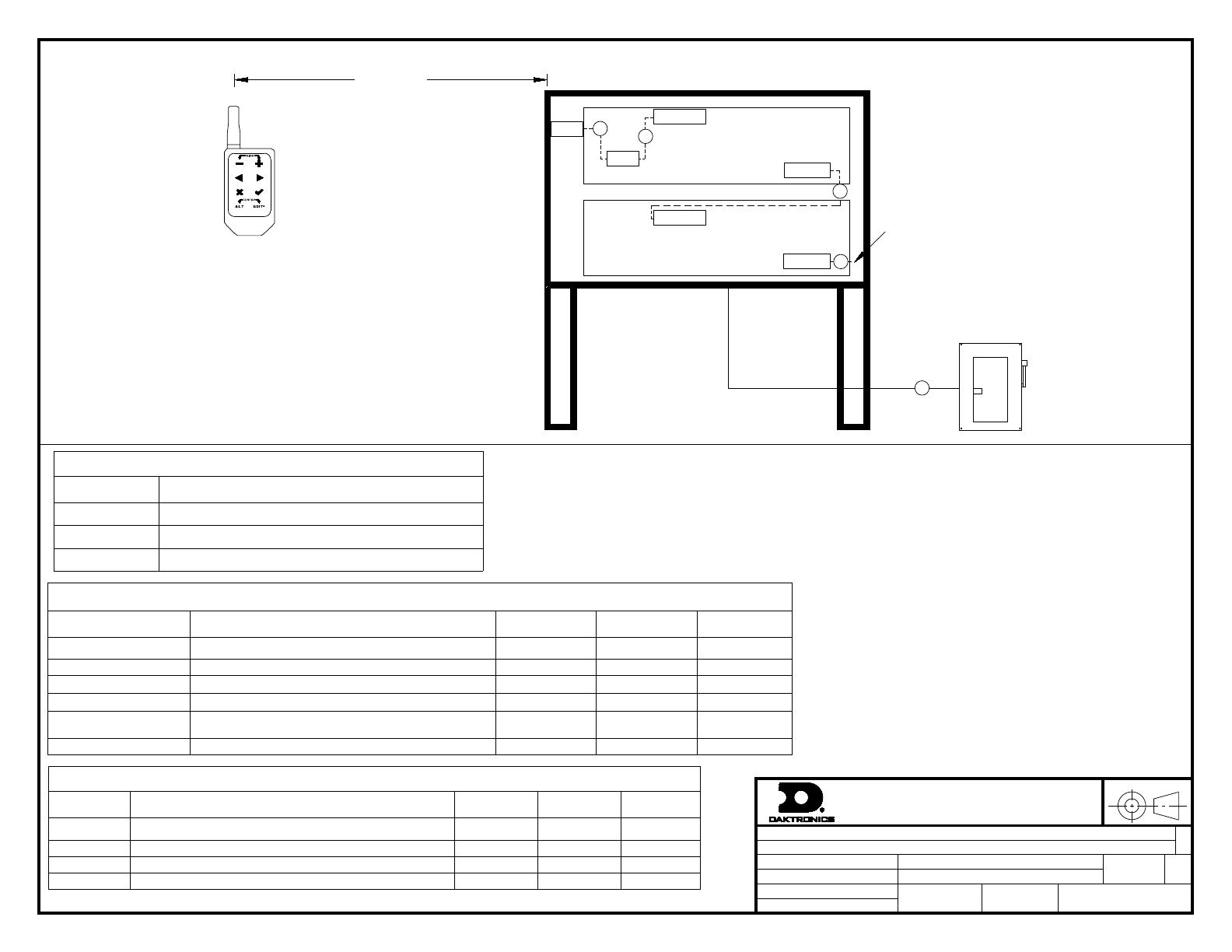
FUELIGHT/DATAMASTER
RISER DIAGRAM; FUELINK KEYFOB, FL-5000
TSPRACK
01 APR 21
P2311 F 01 A
NONE
TSPRACK 4839987
001 OF 1
NOTES
1. POWER FEEDER SIZED AS NEEDED, BY CUSTOMER.
ALL WIRING TO MEET OR EXCEED LOCAL AND
NATIONAL ELECTRICAL CODES. SEE SHOP DRAWING
FOR POWER DRAW PER DISPLAY.
2. PILOT HOLES ARE PROVIDED FOR 3/4" CONDUIT
FITTING ON REAR OF DISPLAY FOR POWER AND
SIGNAL ENTRANCE AND SIGNAL EXIT.
3. REFER TO MANUAL FOR LINE-TO-LINE WIRING
BETWEEN DISPLAYS.
4. REFER TO TABLE A FOR EMOD LOCATION IN THE
DISPLAY.
5. LAST MOD IN BOTTOM DISPLAY WILL CONNECT TO
THE FIRST MODULE IN THE BOTTOM DISPLAY IN THE
OPPOSITE SIDE OF A DOUBLE FACE PYLON.
6. SEE BOM FOR PART NUMBER.
COMPONENT IDENTIFICATION TABLE
COMPONENT DESCRIPTION DAKTRONICS
PART NUMBER
PROVIDED BY INSTALLED BY
MD MAIN DISCONNECT -CUSTOMER CUSTOMER
KR KEYFOB REMOTE ASSEMBLY 0A-2252-0502 DAKTRONICS CUSTOMER
REC KEYFOB REMOTE RECEIVER SEE NOTE 6 DAKTRONICS CUSTOMER
TL MOD TOP LEFT MODULE IN DISPLAY FROM THE FRONT SEE NOTE 6 DAKTRONICS FACTORY
E MOD LAST MODULE IN SIGNAL CHAIN LOCATED IN RIGHT MOST
COLUMN. SEE NOTE 6 DAKTRONICS FACTORY
ANT KEYFOB REMOTE RECEIVER ANTENNA A-2015 DAKTRONICS CUSTOMER
TABLE A: ENDING MODULE (EMOD) LOCATION
DISPLAY SIZE LOCATION (FRONT VIEW)
6", 8" THIS DISPLAY ONLY HAS ONE MODULE.
12", 16", 20" TOP MODULE IN COLUMN FURTHEST TO THE RIGHT
18", 24", 30", 36",48" BOTTOM MODULE IN COLUMN FURTHEST TO THE RIGHT
FUELIGHT DISPLAY
MD
OVERALL SIGN STRUCTURE
FUELIGHT DISPLAY
400FT MAX
D
A
REC
KR
C
ANT TL MOD
E MOD
TL MOD
B
FRONT VIEW
NOTE 3,4
NOTE 1
E MOD
NOTE 3, 4
C
NOTE 5
CABLE IDENTIFICATION TABLE
ID TAG DESCRIPTION DAKTRONICS
PART NUMBER PROVIDED BY INSTALLED BY
ACABLE:ANTENNA BULKHEAD TO RECEIVER, 18" W-2955 DAKTRONICS CUSTOMER
BCABLE; MOD TO MOD; 4 POS MINI MNL, 24" W-4817959 DAKTRONICS CUSTOMER
CCABLE; LINE TO LINE; 4 POS MINI MNL, 15FT W-4821291 DAKTRONICS CUSTOMER
D POWER FEEDER SEE NOTE "1" - CUSTOMER CUSTOMER
LL-5109603 REV00
DAKTRONICS
HOLD TO ACTIVATE
*
PPaarrtt ## -- DDWWGG--0044883399998877VVeerrssiioonn -- 0000..66DDeessccrriippttiioonn -- NN AA RRIISSEERR DDIIAAGGRRAAMM;; FFUUEELLIINNKK KKEEYYFFOOBB,, FFLL--55000000LLiiffeeccyyccllee SSttaattee -- FFuullll PPrroodduuccttiioonn


