Digilent PmodCMPS Owner's manual

Type
Owner's manual

Digilent PmodCMPS, a compact and versatile module, empowers you to add precise compass heading readings to your Digilent host board with an I²C interface. Utilizing Honeywell's HMC5883L with Anisotropic Magnetoresistive (AMR) technology, it delivers accurate 3-axis digital compass readings with a resolution of 2 milli-gauss in ±8 gauss fields. Experience a maximum data output rate of 160 Hz for real-time orientation updates. With its small size of 0.8" × 0.8" (2.0 cm × 2.0 cm), it integrates seamlessly into your designs.

Digilent PmodCMPS, a compact and versatile module, empowers you to add precise compass heading readings to your Digilent host board with an I²C interface. Utilizing Honeywell's HMC5883L with Anisotropic Magnetoresistive (AMR) technology, it delivers accurate 3-axis digital compass readings with a resolution of 2 milli-gauss in ±8 gauss fields. Experience a maximum data output rate of 160 Hz for real-time orientation updates. With its small size of 0.8" × 0.8" (2.0 cm × 2.0 cm), it integrates seamlessly into your designs.

1300 Henley Court
Pullman, WA 99163
509.334.6306
www.digilentinc.com
PmodCMPS Reference Manual
Revised May 24, 2016
This manual applies to the PmodCMPS rev. A
DOC#: 502-285
Copyright Digilent, Inc. All rights reserved.
Other product and company names mentioned may be trademarks of their respective owners.
Page 1 of 2
Overview
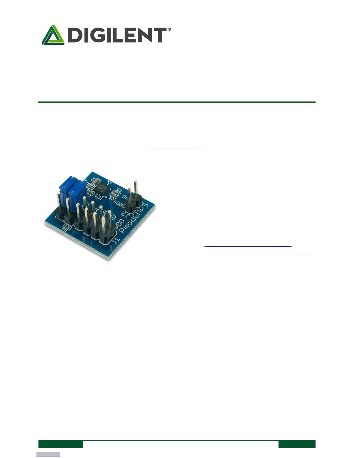
The Digilent PmodCMPS features the popular Honeywell HMC5883L 3-axis digital compass and can add compass
heading readings to any Digilent host board with an I²C interface.
1 Functional Description
The PmodCMPS utilizes Honeywell's HMC5883L with Anisotropic Magnetoresistive (AMR) technology. In plain
English, this means that the three sensors (one for each coordinate direction) have very little interference with
each other so that accurate data can be retrieved from the Pmod.
2 Interfacing with the Pmod
The PmodCMPS communicates with the host board via the I²C protocol. Jumpers JP1 and JP2 provide optional
2.2kΩ pull-up resistors to use for the Serial Data and Serial Clock lines. The 7-bit address for this on-board chip is
0x1E, making the 8-bit address for a read command 0x3D and 0x3C for a write command.
By default, the PmodCMPS starts out in Single Measurement mode so that the compass takes a single
measurement, sets the Data Ready pin high, and then places itself into Idle Mode. While in Idle Mode, major
sources of power consumption are (not surprisingly) disabled, such as the internal ADC which collects the voltage
measurements. However, you can still access all of the registers with their most recent data value through the I²C
The PmodCMPS.
3-axis digital compass
2 milli-gauss Field Resolution in ±8 gauss fields
160 Hz maximum data output rate
Optional pull-up resistors for SCL and SDA pins
Small PCB size for flexible designs 0.8“ × 0.8” (2.0 cm
× 2.0 cm)
2×4-pin connector with I2C interface
Follows Digilent Pmod Interface Specification
Library and example code available in resource center
Downloaded from Arrow.com.
PmodCMPS Reference Manual
Copyright Digilent, Inc. All rights reserved.
Other product and company names mentioned may be trademarks of their respective owners.
Page 2 of 2
bus. To change the PmodCMPS from idle mode back into Single Measurement or Continuous Measurement mode,
the user must write to the Mode Register (0x02).
When reading data from the PmodCMPS, all six data registers, corresponding to the upper and lower bytes of each
Cartesian coordinate direction, must be read. Since the internal register address pointer automatically increments
after a register has been successfully read, it is possible to read from all six registers with a single command. An
example how this might look is given below:
Command byte
Address byte
0
0
1
1
1
1
0
1
(ACK)
0
0
0
0
0
0
1
1
(ACK)
MSB X
LSB X
SX
SX
SX
SX
sb
MSB
b9
b8
(ACK)
b7
b6
b5
b4
b3
b2
b1
b0
(ACK)
MSB Z
LSB Z
SX
SX
SX
SX
sb
MSB
b9
b8
(ACK)
b7
b6
b5
b4
b3
b2
b1
b0
(ACK)
MSB Y
LSB Y
SX
SX
SX
SX
sb
MSB
b9
b8
(ACK)
b7
b6
b5
b4
b3
b2
b1
b0
(STOP)
Table 1. Command and address bytes.
Note: SX stands for a sign extension of the sign bit (sb).
2.1 Pinout Description Table
Header J1
Header J2
Pins
Signal
Description
Pin
Signal
Description
1 & 5
SCL
Serial Clock
1
DRDY
Data Ready
2 & 6
SDA
Serial Data
2
GND
Power Supply Ground
3 & 7
GND
Power Supply Ground
Jumper JP1
4 & 8
VCC
Power Supply (3.3V)
Loaded State
SDA line uses a 2.2kΩ pull-up resistor
Jumper JP2
Loaded State
SCL line uses a 2.2kΩ pull-up resistor
Table 1. Connector J1: Pin descriptions as labeled on the Pmod.
The PmodCMPS also offers a self test mode to help calibrate any data that is being received from the module.
Any external power applied to the PmodCMPS must be within 2.16V and 3.6V; therefore, when using Pmod
headers on Digilent system boards, the supply voltage must be at 3.3V.
3 Physical Dimensions
The pins on the pin header are spaced 100 mil apart. The PCB is 0.8 inches long on the sides parallel to the pins on
the pin header and 0.8 inches long on the sides perpendicular to the pin header.
Downloaded from Arrow.com.Downloaded from Arrow.com.
  • Page 1 1
  • Page 2 2

Digilent PmodCMPS Owner's manual

Type
Owner's manual

Digilent PmodCMPS, a compact and versatile module, empowers you to add precise compass heading readings to your Digilent host board with an I²C interface. Utilizing Honeywell's HMC5883L with Anisotropic Magnetoresistive (AMR) technology, it delivers accurate 3-axis digital compass readings with a resolution of 2 milli-gauss in ±8 gauss fields. Experience a maximum data output rate of 160 Hz for real-time orientation updates. With its small size of 0.8" × 0.8" (2.0 cm × 2.0 cm), it integrates seamlessly into your designs.

Ask a question and I''ll find the answer in the document

Finding information in a document is now easier with AI