Page is loading ...

C8BV & C8DV SERIES SPLIT SYSTEM UNCASED INDOOR COILS
STRAIGHT & DOWNTURN BRAZED INSTALLATIONS
INSTALLATION INSTRUCTIONS
IMPORTANT
ATTENTION INSTALLERS:
It is your responsibility to know this product better than your customer. This includes being able
to install the product according to strict safety guidelines and instructing the customer on how
to operate and maintain the equipment for the life of the product. Safety should always be the
deciding factor when installing this product and using common sense plays an important role as
well. Pay attention to all safety warnings and any other special notes highlighted in the manual.
Improper installation of the coil or failure to follow safety warnings could result in serious injury,
death, or property damage.
These instructions are primarily intended to assist qualified individuals experienced in the proper
installation of this appliance. Some local codes require licensed installation/service personnel
for this type of equipment. Please read all instructions carefully before starting the installation.
Return these instructions to the customer’s package for future reference.
DO NOT DESTROY. PLEASE READ CAREFULLY & KEEP IN A SAFE PLACE FOR FUTURE REFERENCE.
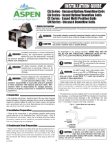
C8BV Uncased Indoor Coil
(Straight Brazed Connection)
C8DV Uncased Indoor Coil
(Downturn Brazed Connection)

2
IMPORTANT SAFETY INFORMATION
Please read all instructions before servicing this equipment.
Pay attention to all safety warnings and any other special
notes highlighted in the manual. Safety markings are used
frequently throughout this manual to designate a degree or
level of seriousness and should not be ignored. WARNING
indicates a potentially hazardous situation that if not avoided,
could result in personal injury or death. CAUTION indicates a
potentially hazardous situation that if not avoided, may result
in minor or moderate injury or property damage.
WARNING:
NITROGEN
HEALTH
FLAMMABILITY
REACTIVITY
0 Minimal Hazard
1 Slight Hazard
1
0
0
C8(B,D)V coils are pressurized with Nitrogen
at the factory. Avoid direct face exposure or
contact with valve when gas is escaping. Always
ensure adequate ventilation is present during
the depressurization process. Any uncertainties
should be addressed before proceeding.
WARNING:
This coil must be installed in accordance
with the instructions outlined in this manual
during the installation, service, and operation
of this unit. Unqualified individuals should
not attempt to interpret these instructions or
install this equipment. If you do not posses
mechanical skills or tools, call your local dealer
for assistance. Under no circumstances should
the equipment owner attempt to install and/or
service this equipment. Failure to follow safety
recommendations could result in possible
damage to the equipment, serious personal
injury or death.
WARNING:
Improper installation, service, adjustment, or
maintenance may cause explosion, fire, electrical
shock or other hazardous conditions which may
result in personal injury or property damage.
Unless otherwise noted in these instructions,
only factory authorized kits or accessories may
be used with this product.
WARNING:
PROPOSITION 65 WARNING: This product
contains chemicals known to the state of
California to cause cancer, birth defects or other
reproductive harm.
• Theinstallermustcomplywithalllocalcodesandregulations
which govern the installation of this type of equipment.
Local codes and regulations take precedence over any
recommendations contained in these instructions. Consult
local building codes for special installation requirements.
• Familiarize yourself with the controls that shut off the
electrical power to the unit. If the unit needs to be shut down
for an extended period of time, turn off electrical power
atthecircuitbreaker.Foryoursafetyalwaysturnoffthe
electrical power before performing service or maintenance
on the unit.
• Installationofequipmentmayrequirebrazingoperations.
Installer must comply with safety codes and wear
appropriate safety equipment (safety glasses, work gloves,
fire extinguisher, etc.) when performing brazing operations.
• Read the Installation Instructions supplied with the air
handler. Always observe all safety requirements outlined
in this manual and on the air handler markings before
installing the coil.
• Followallprecautionsintheliterature,ontags,andon
labelsprovidedwiththeequipment.Readandthoroughly
understand the instructions provided with the equipment
prior to performing the installation and operational checkout
of the equipment.
GENERAL INFORMATION
C8BV & C8DV series coils are designed for upflow or
downflow applications and are equipped with braze type
refrigerant connections for easy installation.
• Cooling/heating equipment must be properly sized
and installed in accordance with the manufacturer’s
specifications and approved recommendations.
• Verifythattheairdeliveryofthecoil/airhandlerisadequate
to handle the static pressure drop of the coil, filter, and
duct work.
• Ifpreciseformingofrefrigerantlinesisrequired,acopper
tubing bender is recommended. Avoid sharp bends and
contact of the refrigerant lines with metal surfaces.
• Refrigerantlinesshouldbewrappedwithpressuresensitive
neoprene or other suitable material where they pass against
sharply edged sheet metal.
• Close-offplatesareavailableinsomeairlterkits.Refer
totheReplacementPartsListforavailablepartnumbers.
Installthenecessaryclose-offplatesaroundtherefrigerant
linesanddrainlinewhererequired.Reinstallallinnerand
outerpanelsofthecoil/airhandlerthatwerepreviously
removed when installing the indoor coil.

3
COIL INSTALLATION
WARNING:
ELECTRICAL SHOCK OR FIRE HAZARD
Failure to follow safety warnings exactly could
result in serious injury or property damage.
Improper servicing could result in dangerous
operation, serious injury, death or property
damage.
• Beforeservicing,disconnectallelectricalpower
to the air handler and outdoor unit.
• Whenservicingcontrols,labelallwiresprior
to disconnecting. Reconnect wires correctly.
• Verifyproperoperationafterservicing.
CAUTION:
The coil must be level to ensure proper
condensate drainage. An unlevel installation may
result in structural damage, premature equipment
failure, or possible personal injury.
ForrecommendedBTUHcapacities,nominalCFM,andcoil
dimensions refer to
Figure2(page5) and Table1(page
5). For matching airhandlermodels refer to Table 2. To
install the indoor coil, follow the steps below:
1.Removedoor cover plate, door and coil close-offplate
(with insulation). Discard door cover plate.
2. UpowApplications: Slide the coil into the track located
in the bottom of the unit.
Downflow Applications:Thedownowadaptor must be
used. Install the downflow adaptor and coil as directed in
the instructions supplied with the kit.
3.Reinstallthedoorandcoilclose-offplate(withinsulation).
NOTE:Indownowapplicationsthedoorisrotated180°
so that the refrigerant and condensate lines remain on the
left side.
4. Install the linesets as outlined in the “Connecting the
Linesets” section above. Run the condensate drain
according to the guidelines in the “Condensate Drain”
section below.
Refrigerant Line Connections
System Depressurization
1.Removethecap(Figure1) from the end of the liquid line.
2. Verify pressurization by depressing the Schrader valve
on the end of the liquid line. Listen for any escaping gas.
If there is no pressure, test the coil for leakage.
• Ifleakageisfound,clearlymarkthelocationoftheleak
and return the coil to the distributor for processing.
• Ifnoleaksarefound,thecoilmaybeinstalled.
3. Depress the valve to relieve all pressure from the coil.
Connecting the Linesets
1.Route and cut both lineset tubes to proper length in
accordance with the outdoor unit specifications. Verify
the ends are round, clean, and free of any burrs.
2.Cutoffthe ttingonthe3/8”lineofthe coil.Swageas
needed to fit the line set.
3. Connect the suction and liquid lineset tubes.
CAUTION:
It is recommended that a wet rag be wrapped
around the suction line in front of the close
off plate before applying heat. Failure to keep
components cool during brazing may result in
structural damage, premature equipment failure,
or possible personal injury.
4. Braze the individual connections with dry nitrogen flowing
throughthejoints.Thiswillpreventinternaloxidationand
scaling from occurring.
IMPORTANT: To prevent internal oxidation and scaling
from occuring, braze all connections with dry nitrogen
flowing through the joints.
5. Wrap the refrigerant lines with pressure sensitive neoprene
or other suitable material especially where the lines enter
the opening in the sheet metal.
6.Evacuatethesystemofmoistureandnon-condensables
to prevent low efficiency operation or damage to the unit.
Thesuggestedrangeofevacuationis250-500microns.
7. Charge the system with refrigerant. Please Refer to the
outdoor unit installation manual for additional charging
instructions.
8. Check the system for leaks, including the lineset and the
brazed joints.
NOTE: Apply a soap and water solution on each joint or
union with a small paintbrush. If bubbling is observed, the
connection is not adequately sealed.
9. Properly dispose of all removed parts.
Condensate Drain
CAUTION:
The coil must be level to ensure proper condensate
drainage. Improper condensate disposal may
result in structural damage, premature equipment
failure, or possible personal injury.
Suction
Line
Liquid
Line
Schrader
Valve
Cap
Figure 1. Suction & Liquid Line Locations

4
• Methods for disposing of condensate vary according
tolocalcodes.Refertolocalcodesorauthorityhaving
jurisidiction for restrictions and proper condensate disposal
requirements.
• Allcondensatepanshaveprimaryandsecondarydrain
connectionstomeetFHArequirements.Iftheapplication
is located in or above a living space where damage may
resultfromcondensateoverow,aseparate3/4inchdrain
must be provided from the secondary drain connection and
a secondary drain pan must be installed under the entire
unit.Runsecondarydrainlinestoaplacewheretheyare
noticeable if used.
• Thecoilcondensatepanisdesignedwith3/4”NPSCdrain
connections.UseaPVCorsimilarmaterialttingtoattach
the drain line to the pan.
NOTE: The fitting should be hand tightened only.
Overtightening may crack the drain pan and cause
condensate to leak.
• The drain pan MUST be drained with factory supplied
tubing and looped to form a trap.
IMPORTANT: Failure to install a trap may result in
condensation overflowing the drain pan, resulting in
substantial water damage to surrounding area.
• Primethetrapwithwater.Insulatethedrainifitislocated
in an unconditioned space, and test the condensate line
for leaks. Consult local codes for additional restrictions or
precautions.
• Routethelinestoasuitabledrain,avoidingsharpbends
and pinching of the lines. The drain should maintain a
minimum horizontal slope in the direction of discharge of
notlessthan1”verticalforevery10ftofhorizontalrun.
• During system checkout, inspect the drain line and
connections to verify proper condensate drainage.
MAINTENANCE & SERVICE
WARNING:
ELECTRICAL SHOCK OR FIRE HAZARD
Failure to follow safety warnings exactly could
result in serious injury or property damage.
Improper servicing could result in dangerous
operation, serious injury, death or property
damage.
• Beforeservicing,disconnectallelectricalpower
to the unit.
• Whenservicingcontrols,labelallwiresprior
to disconnecting. Reconnect wires correctly.
• Verifyproperoperationafterservicing.
CAUTION:
Do not operate the system without a suitable filter
in the return air duct system. Always replace the
filter with the same size and type.
Toensureoptimumperformanceandtominimizepossible
equipment failure, the following maintenance tasks should
be performed periodically on this equipment:
1.Theairlterinstalledwiththesystemshouldbechecked
and cleaned or replaced twice per year.
2. Check the coil, drain pan, and condensate drain line for
cleanliness at the start of each heating and cooling season.
Clean as needed.

5
Table 1. Coil Specifications
C8(B,D)VM X36 X42 X48
NominalCapacity(BTUH) 36,000 42,000 48,000
NominalAirow(CFM) 1,200 1,400 1,600
W-Width(in.) 181/8 211/16 211/16
H-Height(in.) 18 243/4 283/4
Connection-LiquidLine(in.) 3/8 3/8 3/8
Connection-SuctionLine(in.) 3/4 7/8 7/8
NOTES:
1.RefertosalesspecicationsheetsforListed/Certiedcombinationsofequipmentandrequiredaccessories.
2.RefertothecurrentAHRIdirectoryforcertiedratingsofsplitsystems.
Figure 2. C8BV & C8DV Coil Dimensions
2 1/2”
W
19 1/2”
1 3/8”
1”
12 1/8”
14 1/2”
H
C8BV
2 1/2”
W
19 1/2”
1 3/8”
1”
10”
10 7/8”
H
C8DV
COIL MODEL AIR HANDLER MODEL
C8BVMX36U-B
B6BV-000K-B-10
B6BV-000K-B-15
C8DVMX36U-B
B6BV-000K-B-10
B6BV-000K-B-15
C8BVMX42U-C B6BV-000K-C-20
C8DVMX42U-C B6BV-000K-C-20
C8BVMX48U-C B6BV-000K-C-20
C8DVMX48U-C B6BV-000K-C-20
Table 2. Air Handler Matches

6

7

INSTALLER: PLEASE LEAVE THESE INSTRUCTIONS WITH THE EQUIPMENT OWNER.
10144200 (NEW)
Specications&illustrationssubjecttochangewithoutnoticeorincurringobligations(08/16).
©NortekGlobalHVACLLC2016.AllRightsReserved.
/