
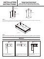
This Roof Curb is NRCA approved and is constructed of 18 gauge galvanized steel with a full perimeter 2" x 4" wood nailer
strip. The curb is designed to be used with the Cooling, Gas Electric, and Heat Pump Models. The curb is shipped with the
following parts, (see figure 2):
Step 2:
Layout the curb pieces before assembly to insure that all the necessary pieces are included.
Step 1:
Curb Package is shown as shipped with easy to identify part numbers on all sides. Cut shipping bands and remove
Hardware, Gasket Material, and 4 Duct Supports.
(B)
(E)
(C)
(C)
(A)
(B)
(A)
1) 2 ea. Curb Short Sides - 50
7
8
" Long (A)
2) 2 ea. Curb Long Sides - 94
7
8
" Long (B)
3) 2 ea. Vertical Duct Support - 46
7
8
" Long (C)
4) 1 ea. Horizontal Duct Support - 21 ½" Long (D)
5) 1 ea. Horizontal Duct Support - 33" Long (E)
6) 1 ea. Hardware Package Includes:
4 ea. "Hinge" Pins
3
16
"
8 ea. Hex Washers screws #10 x ½"
7) 3 ea. Gasket ¾" x 1 ¼" x 14' (42 ft. total)
U.S. PATENT 5148647
FORM# 606A-1210 (606A-0808)
(D)
INSTALLATION INSTRUCTIONS FOR
547860 / 547861 / 547862 / 547863
ROOF CURBS USED WITH Q5SN/Q6SP 090-120
R6GP/P6SP 072-120 / GR4GN/GP4SN 090-120 UNITS
INSTALLATION
INSTRUCTIONS
Fig ure 1
Fig ure 2

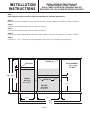
1.
Duct Support flange goes in slot on
curb. Screw Brace to curb.
Brace inter-locks
with curb.
Step 4:
After the four corners are assembled; the curb should be checked to be sure it is in "square". Do this by measuring
diagonally from each opposite corner as shown in Figure 5. The two measurements should be the same for each direction.
Step 3:
Corner Assembly: Align each curb side as shown in Figure 3. Using a hammer, drive the curb "hinge" pin down until the
top of the pin is below the top of the curb as shown in Figure 4.
DETAILS
2.
Duct Support flange goes in slot on
pan or other brace. Screw brace
together.
Brace inter-locks
with pan or other
brace.
3.
Tab rests on top of curb for
added support.
Duct Support is supported by "tabs".
Screw pan to curb.
INSTALLATION INSTRUCTIONS FOR
547860 / 547861 / 547862 / 547863
ROOF CURBS USED WITH Q5SN/Q6SP 090-120
R6GP/P6SP 072-120 / GR4GN/GP4SN 090-120 UNITS
Fig ure 5
INSTALLATION
INSTRUCTIONS
HINGE
Fig ure 4
Fig ure 3
HINGE PIN
TAPERED END
CURB SIDE

Step 5:
Install the vertical duct support (C) as shown with opening over the desired duct location as shown in Figure 6.
Step 6:
Install the horizontal duct support (D) as shown in Figure 6.
Step 7:
Install the horizontal duct support (E) as shown in Figure 6.
Step 8:
If the curb is being assembled and moved to another location, attach the duct supports as shown in "Details".
Step 9:
Place the ¾" x 1 ¼" Gasket on all of the top edges of the Roof Curb, including the duct supports.
90
7
8
46
7
8
21 ½
94
7
8
50
7
8
33
33
2
(E)
21 ½
(C) (C)
DE TAIL #2
SUPPLY
Duct size
21" x 32 ½"
ROOF OPEN ING
58 ½" Long
33" Wide
Fig ure 6
DE TAIL#1
Note:
Duct Supports can be located on either end depending on individual applications.
INSTALLATION INSTRUCTIONS FOR
547860 / 547861 / 547862 / 547863
ROOF CURBS USED WITH Q5SN/Q6SP 090-120
R6GP/P6SP 072-120 / GR4GN/GP4SN 090-120 UNITS
2
44
DETAIL #3
RETURN
Duct size
21" x 32 ½"
(D)
INSTALLATION
INSTRUCTIONS

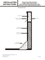
CURB FRAME
CANT STRIP
(FIELD SUPPLIED)
WOOD NAILER
COUNTER FLASHING
(FIELD SUPPLIED)
ROOFING FELT
(FIELD SUPPLIED)
RIGID INSULATION
(FIELD SUPPLIED)
ROOF INSTRUCTIONS
NEICRB07
SUPERSEDES 08-26-08
DECEMBER 6, 2010
INSTALLATION INSTRUCTIONS FOR
547860 / 547861 / 547862 / 547863
ROOF CURBS USED WITH Q5SN/Q6SP 090-120
R6GP/P6SP 072-120 / GR4GN/GP4SN 090-120 UNITS
INSTALLATION
INSTRUCTIONS
© Nortek Global HVAC
, LLC 2015. All Rights Reserved.
-
 1
1
-
 2
2
-
 3
3
-
 4
4


Unbranded Q6SP Installation guide
- Type
- Installation guide
- This manual is also suitable for
Ask a question and I''ll find the answer in the document
Finding information in a document is now easier with AI
Related papers
-
Unbranded Concentric Curb Transition, 547869, 547878 Installation guide
-
Reznor R6GP Installation guide
-
Reznor R6GN Installation guide
-
-
-
-
-
-
Nordyne P6SP-090 Series Installation guide
-
Reznor P6SP Installation guide
Other documents
-
-
Ducane PRDF14 Installation guide
-
Blueridge PRGE14 Installation guide
-
Reznor R6GN Installation guide
-
-
-
-
Rheem RXKG-CAE14 Installation guide
-
York R-Series User guide
-