Frigidaire GLWY1343AS1 Installation guide
- Type
- Installation guide

Installation
Instructions
Full Size Automatic Washer
Before beginning installation, carefully read these instructions. This will simplify the
installation and ensure the washer is installed correctly and safely. Leave these instructions
near the washer after installation for future reference.
NOTE: The electrical service to the washer must conform with local codes and ordinances
and the latest edition of the National Electrical Code, ANSI/NFPA 70, or in Canada, CSA
22.1 Canadian Electrical Code Part 1.
Contents
SUBJECT PAGE
Pre-lnstallation Requirements 2
Electrical Requirements 2
Grounding Requirements 2
Water Supply Requirements 2
Drain Requirements 2
Rough-In Dimensions 3
Location 3
Unpacking 3
Installation 3-4
Replacement Parts 4
Printed in U.S.A. P/N 131964000 (0004)

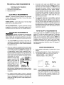
PRE-INSTALLATION REQUIREMENTS
Tools Required for Installation:
1. 3/8 in. socket with ratchet.
2. Channel-lock adjustable pliers.
3. Carpenter's level.
ELECTRICAL REQUIREMENTS
CIRCUIT - Individual, properly polarized and grounded
15 amp. branch circuit fused with 15 amp. time delay
fuse or circuit breaker.
POWER SUPPLY - 2 wire, with ground, 120 volt, single
phase, 60 Hz, Alternating Current.
OUTLET RECEPTACLE - Properly grounded 3-prong
receptacle to be located so the power supply cord is
accessible when the washer is in an installed position.
GROUNDING REQUIREMENTS
Improper connection of the equipment
grounding conductor can result in a risk of electrical
shock. Check with a licensed electrician if you are in
doubt as to whether the appliance is properly grounded.
1.
The washer MUST be grounded. In the event of a
malfunction or breakdown, grounding will reduce the
risk of electrical shock by a path of least resistance
for electrical current.
2.
Since your washer is equipped with a power supply
cord having an equipment-grounding conductor and
a grounding plug, the plug MUST be plugged into
an appropriate, copper wired receptacle that is
properly installed and grounded in accordance with
all local codes and ordinances or in the absence of
local codes, with the National Electrical Codes,
ANSI/NFPA 70 (latest
edition). If in doubt, call a
licensed electrician. DO
NOT cut off or alter the
grounding prong on the
power supply cord. In
situations where a two-
slot receptacle ispresent,
it is the owner's responsi-
_ Do not, under ;,_
any circurNstances,
cut* remove m
orbypassth@
grounding prong. S
Powersupply
cordwith 3- rong
grounding pl_urg
bility to have a licensed electrician replace itwith a
properly grounded three prong grounding type
receptacle.
3.
For added personal safety, connect a separate
ground wire (No. 18 minimum) from a top panel hinge
screw on the rear of the washer to a grounded cold
water pipe. DO NOT ground to a gas supply pipe or
hot water pipe.
4. Grounded cold water pipe MUST have metal
continuity to electrical ground and MUST register no
more than 25 ohms resistance. It MUST not be
interrupted by plastic, rubber, or other electrical
insulating connectors such as hoses, fittings,
washers, gaskets (including water meter or pump).
Any electrically insulated connector should be
jumped with a length of No. 4 copper wire securely
clamped to bare metal at both ends with a UL
approved ground clamp.
5. If a grounded water pipe is not available, a ground
rod MUST be used and register no more than 25
ohms resistance when in the ground. Drive the rod
into the ground outside the dwelling and connect a
grounding wire (12 AWG or heavier) between the
grounding screw and the grounding rod. It may take
more than one ground rod to not exceed 25 ohms
resistance to ground.
WATER SUPPLY REQUIREMENTS
Hot and cold water faucets MUST be installed within 42
inches (107 cm) of your washer's water inlet.The faucets
MUST be 3/4 inch (1.9 cm) garden hose type so inlet
hoses can be connected. Water pressure MUST be
between 10 and 120 pounds per square inch (maximum
unbalance pressure, hot vs. cold, 10 psi.) Your water
department can advise you of your water pressure. The
hot water temperature should be about 140 degrees F
(60 degrees C).
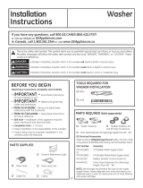
DRAIN REQUIREMENTS
1. Drain capable of eliminating 17 gallons (64.3 L) per
minute.
2. Astandpipe diameter of 1-1/4 in. (3.18 cm) minimum.
3. The standpipe height above the floor should be:
Minimum height: 33in. (83.82 cm)
Maximum height: 96 in. (244 cm)
-f
1" 96" Max.
33" Min. (244 cm)
(83.82 cm)
$ $
NOTE:
For installations requiring a longer drain hose,
have a qualified technician install a longer drain
hose, P/N 131461201. For drain systems in
the floor, install a syphon break kit, P/N
5377678100. Both parts are available from an
authorized parts distributor.
2

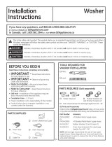
ROUGH-IN DIMENSIONS
_ 27"_
(68.58cm)
FRONT VIEW
_ 27"_
(68.58cm)
SIDE VIEW
LOCATION OF YOUR WASHER
DO NOT INSTALL YOUR WASHER:
1. In an area exposed to dripping water or outside
weather conditions. The ambient temperature should
never be below 60 degrees F (15.6 degrees C) for
proper washer operation.
2. In an area where itwilt come in contact with curtains
or drapes.
3. In an area (garage or garage-type building) where
gasoline of other flammables are kept or stored
(including automobiles).
4. On carpet. Floor MUST BE SOLID with a maximum
slope of 1 in. (2.54 cm). To ensure vibration or
movement does not occur, REINFORCEMENT of
the floor may be necessary.
IMPORTANT MINIMUM INSTALLATION CLEARANCES
When installed in alcove: Sides = 0" (0 cm),
Rear = 0" (0 cm), Top = 20" (50.8 cm).
When installed in closet: Sides = 0" (0 cm),
Rear = 0" (0 cm), Top = 20" (50.8 cm), Front = 1"
(2.54 cm).
Closet door ventilation required: 2 Iouvered openings
each 60 square inches (387 cm2)-- 3 inches (7.6 cm)
from bottom and top of door.
UNPACKING
1. Using the four shipping carton corner posts (two on
each side), carefully lay the washer on its left side
and remove foam shipping base.
2. Using a ratchet with 3/8" socket, remove the
mechanism shipping bolt and plastic spacer block
from the center of the base.
NOTE: If the washer is to be transported at a later
date, the tub blocking pad, shipping bolt, and
plastic spacer block should be retained.
MECHANISM
SHIPPING
BOLT
PLASTIC
SPACER
BLOCK
SHIPPING BLOCKS
i cm) FOAM / \
SHIPPING POWER
PAD CORD
SHIPPING CARTON
CORNER POSTS
DRAIN HOSE
3. Return the washer to an upright position.
4. Remove the tape holding the lid shut and open the
lid.
5. Remove the foam tub blocking pad.
6. Remove the inlet hoses and enclosure package from
the tub.
7.
.
From the back of the washer, remove only the WIRE
shipping clips that secure the drain hose to the left
side of the washer backsheet. DO NOT REMOVE
THE PLASTIC CLAMPS on the right side of the
washer. These clamps form a standpipe to prevent
water siphoning.
Carefully move the washer to within 4 feet of the
final location for the start of the installation.
1.
2.
.
INSTALLATION
Run some water from the hot and cotd faucets to
flush the water lines and remove particles that might
ctog up the water valve screens.
Remove the inlet hoses and rubber washers from
the plastic bag and install the rubber washers in each
end of the inlet hoses.
Carefully connect the inlet
hose marked "HOT" to the
bottom outlet of the water
valve. Tighten by hand, then
tighten another 2/3 turn with
pliers. Carefully connect the
other inlet hose to the top
outlet of the water valve.
Tighten by hand, then tighten
another 2/3 turn with pliers.
DO NOT CROSS THREAD OR
OVERTIGHTEN THESE CONNECTIONS.
3

4.
.
6.
7.
Determine which water faucet is the HOT water
faucet and carefully connect the bottom inlet hose to
the HOT water faucet, tighten by hand, then tighten
another 2/3 turn with pliers. Carefully connect the
top inlet hose to the COLD water faucet, tighten by
hand, then tighten another 2/3 turn with pliers.
DO NOT CROSS THREAD OR
OVERTIGHTEN THESE CONNECTIONS.
Turn the water on and check for leaks at both
connections.
Carefully move the washer to its final location.
To ensure the washer is level and solid on all four
legs, open the lid, grasp the top panel and tilt the
washer forward so the rear legs are off the ground.
Gently set the washer back down to allow the rear
legs to self adjust. Place a level on top of the washer.
Check it side to side, then front to back. Screw the
front leveling legs up or down to ensure the washer
is resting solid on all four legs (no rocking of the
washer should exist).
NOTE: Keep the leg extension at a minimum to
prevent excessive vibration. The farther out
the legs are extended the more the washer
will vibrate.
CABLE TiE
Form a "U" shape on the end of the drain hose with
the hose pointed toward the drain. Place the formed
end in a laundry tub or a standpipe and secure with
a cable tie provided in the enclosure package.
NOTE:
The standpipe inside diameter must be
1-1/4" (3.18 cm) minimum. There must be
an air gap around the drain hose in the
standpipe. A snug hose fit can cause a
siphoning action.
8. Plug the power cord into a grounded outlet.
NOTE: Check to ensure the power is off at acircuit
breaker/fuse box before plugging the
power cord into an outlet.
9. Turn on the power at a circuit breaker/fuse box.
10. Read the Operating Instructions and Owner's Guide
provided with the washer. They contain valuable and
helpful information that will save you time and money.
11. Run the washer through a complete cycle. Check
for water leaks and proper operation.
12. If your washer does not operate, please review the
"Avoid Service Checklist" located in your Owner's
Guide before calling for service.
13. Place these instructions ina location near the washer
for future reference.
NOTE: A wiring diagram is located inside the washer
console.
REPLACEMENT PARTS
UNITED STATES
If replacement parts are needed for your washer, contact
the source where you purchased your washer or call
1-800-944-9044 for the Frigidaire Company Authorized
Parts Distributor nearest you.
CANADA
If replacement parts are needed for your washer, contact
your local dealedretailer or call (905) 565-9200 for the
authorized Frigidaire Parts and Service depot nearest
you.
Destroy the carton and plastic bags after
the washer is unpacked. Children might use them for
play. Cartons covered with rugs, bedspreads, or plastic
sheets can become airtight chambers causing
suffocation. Place all materials in a garbage container or
make materials inaccessible to children.
rl''r/-'_qL'lh'[q The instructions in this manual and all
other literature included with this washer are not meant
to cover every possible condition and situation that may
occur. Good safe practice and caution MUST be applied
when installing, operating and maintaining any appliance.
Maximum benefits and enjoyment are achieved when
all the Safety and Operating instructions are
understood and practiced as a routine with your
laundering tasks.
4
-
 1
1
-
 2
2
-
 3
3
-
 4
4


Frigidaire GLWY1343AS1 Installation guide
- Type
- Installation guide
Ask a question and I''ll find the answer in the document
Finding information in a document is now easier with AI
Related papers
-
Frigidaire LWS3312DS0 Installation guide
-
Frigidaire FWS833AS2 Installation guide
-
Crosley GLWS1439FC2 Installation guide
-
Frigidaire GLWS1439FS Installation guide
-
Frigidaire GLGT1031FS - 3 cu. Ft. Laundry Center User manual
-
Universal/Multiflex (Frigidaire) GCET1031FS4 Installation guide
-
Frigidaire FLXG52RBSA Installation guide
-
Frigidaire FLXG52RBSA Installation guide
-
Frigidaire GLET1142FS0 Installation guide
-
Frigidaire FLCG7522AW User manual
Other documents
-
Kenmore 134966700 User manual
-
White-Westinghouse SWS1649HQ0 Installation guide
-
 GE Appliances GTW680BSJWS Installation guide
-
 GE Appliances GTW460ASJWW Installation guide
-
Crosley YTW4514PNDG User manual
-
Kenmore 41797822700 Installation guide
-
KitchenAid KUIA18NNJ User manual
-
Electrolux ELTW20XAKW0 Owner's manual
-
Electrolux 134700400 User manual
-

