
Installation
Instructions
ElectricDryer
37
I
Questions on Installation? Call: 1-8OO-GECARES (US)
or Visit our Web site at: www.GEAppliances.com (US)
BEFOREYOU BEGIN
Read these instructions completely and carefully.
•IMPORTANT -Savethese
instructions for local inspector's use.
•IMPORTANT -Observeall
governing codes and ordinances.
• Note to Installer - Be sure to leave these instructions with
the customer.
• Note to Customer - Keep these instructions with your Use
and Care Book for furore reference.
• Exhausting the dryer to the outdoors is strongly recom-
mended to prevent large amounts of moisture from being
blown into the room.
• Before the old dryer is removed from service or discarded,
remove the dryer door.
• Service information and the wiring diagram are located in
the control console.
• Do not allow children on or in the appliance. Close
supervision of children is necessary when the appliance is
used near children.
FORYOUR SAFETY:
WARNING
• Use only rigid metal or flexible metal 4-in. diameter
ductwork for exhausting to tile outdoors. Never
use plastic or other combustible, easy-to-puncture ductwork.
• This appliance must be properly grounded and installed
as described in these instructions.
• Do not install or store appliance in an area where it
will be exposed to water and/or weather
• Install tile dryer where the temperature is above ,50°F
for satisfactory operation of the dryer control system.
NOTE: Installation and service of this dryer
requires basic mechanical and electrical skills.
It is your responsibility to contact a qualified
installer to make the electrical connections,
I
TOOLS YOU
WILL NEED
SLIPJOINTPLIERS
[_
FLATBLADESCREWDRIVER
PHILLIPSSCREWDRIVER
MATERIALSYOU WILL NEED
4" DIA.METALDUCT
4"
(RECOMMENDED) DUCT
CLAMPS(2)
OR
4"SPRING
CLAMPS(2)
4"DIA.FLEXIBLEMETALDUCT
(IFNEEDED)
%
4"DIA.METAL
ELBOW
EXHAUSTHOOD SAFETYGLASSES
_ 3/4"_RELIEF
DUCTTAPE GLOVES ULRECOGNIZED
DRYERPOWER
CORDKIT
(NOTPROVIDED
WITHDRYER)
ULRATED120/240V,30A
WITH3OR4PRONGS.
IDENTIFYTHEPLUGTYPE
ASPERTHEHOUSE
RECEPTACLEBEFORE
PURCHASINGLINECORD.
Step 1
Step 2
Step 3
Step 4
Step 5
Step 6
Step 7
Prepare the Area and Exhaust for Installation of
New Dryer (see section 1).
Check and Ensure the Existing External Exhaust is
Clean (see section 1) and Meets Attached Installation
Specifications (see section 3).
Remove the Foam Shipping Pads (see section 1).
Move the Dryer to the Desired Location.
Connect the Power Supply (see section 2).
Connect the External Exhaust (see section 4).
Level Your Dryer (see section ,_).
Step 8
Step 9
Check the Operation of the Power Supply
and Venting.
Place the Owners Manual and the Installation
Instructions in a Location Where They Will Be
Noticed By tile Owner.
For Alcove or Closet Installation, see section 6.
For Bathroom or Bedroom Installation, see section 7.
For Mobile or Manufactured Home see, section 8.
For side or bottom exhaust, see section 9.

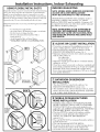
Installation Instructions
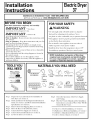
Minimum Clearance Other Than Alcove or Closet Installation
Minimum clearance to combustible surfaces and for air opening are: 0 in. clearance both sides and 1 in. rear. Consideration
must be given to provide adequate clearance for installation and service.
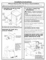
[] PREPARING FOR INSTALLATION
OF NEW DRYER
EXTERNAL
DUCT
OPENING
DUCTTAPEOR
DUCTCLAMP
4"METALDUCT
DUCTTAPEOR
DUCTCLAMP
TIP: Install your dryer before installing your washer.
This will allow better access when installing dryer exhaust.
REMOVING LINT FROM WALL
EXHAUST OPENING
INTERNALDUCT
WALL
CHECKTHATEXHAUST
DAMPEROPENS
ANDCLOSESFREELY.
TILTTHEDRYERSIDEWAYS
ANDREMOVETHEFOAM
SHIPPINGPADSBY
PULLINGATTHESIDES
ANDBREAKINGTHEM
AWAYFROMTHEDRYER
LEGS.BESURETO
REMOVEALLOFTHE
FOAMPIECESAROUND
THELEGS,
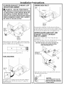
[] ELECTRICAL CONNECTION
INFORMATION
WARNING- TO REDUCE THE RISK OF
FIRE, ELECTRICAL SHOCK AND PERSONAL
INJURY:
DO NOT USE AN EXTENSION CORD OR AN
ADAPTER PLUG WITH THIS APPLIANCE.
Dryer must be electrically grounded in accordance with
local codes and ordinances, or in the absence of local
codes, in accordance with the NATIONAL ELECTRI-
CAL CODE, ANSI/NFPA NO. 70.
ELECTRICAL REQUIREMENTS
This dryer must be connected to an individual branch circuit,
protected by the required time-delay fuses or circuit breakers. A
four or three-wire, single phase, 120/240V or 120/208V, 60Hz,
30 amp circuit is required.
If the electric supply does not meet the above specifications, then
call a licensed electrician.
GROUNDING INSTRUCTIONS
This dryer must be connected to a grounded metal, permanent
wiring system, or an equipment-gxounding conductor nmst be nm
with the circuit conductors and connected to the equipment-
grounding terminal on the appliance.
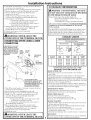
CONNECTING DRYER USING 4-WIRE
CONNECTION (MUST BE USED FOR
MOBILE HOME INSTALLATION)
NOTE: Since January 1, 1996, the National Electric Code
requires that new constructions utilize a 4 wire connection
to an electric dryer.
REMOVEGROUNDSTRAP-
ANDDISCARD.KEEPGREEN
GROUNDSCREW
HOT
WIRE RELOCATEGREEN
GROUNDSCREW
HERE
GREENOR
2 WITHUPTURNEDENDS(

Installation Instructions
1. Turn off the circuit breaker (s) (30 amp) or remove the dryer's
circuit fuse at the electrical box.
2. Be sure the dryer cord is unplugged from tile wall receptacle.
3. Remove the power cord cover located at the lower back.
4. Remove and discard ground strap. Keep the green
ground screw for step 7.
5. Install 3/4 in. UL recognized strain relief to power
cord entry hole. Bring power cord through strain relief.
6. Connect power cord as follows:
A. Connect the 2 hot lines to the outer screws of
the terminal block (marked L1 and L2).
B. Connect the neutral (white) line to tile center of
the terminal block (marked N).
7. Attach ground wire of power cord with the green ground
screw (hole above strain relief bracket). Tighten all
terminal block screws (3) completely.
8. Properly secure power cord to strain relief.
9. Reinstall the coven
,_WARNING: NEVER LEAVE THE
COVER OFF OF THE TERMINAL BLOCK.
CONNECTING DRYER USING 3-WIRE
CONNECTION
IFREQUIRED,BYLOCALCODE,
INSTALLEXTERNALGROUND
(NOTPROVIDED)TOGROUNDED
METAL,COLDWATERPIPE,OR GREEN GROUND
OTHERESTABLISHEDGROUNDGROUND _TRAP
DETERMINEDBYAQUALIFIEDSCREW
ELECTRICIAN. HOT
WIRE
STRAINRELIEF
BRACKET
3/4",UL
RECOGNIZED
RELIEF
NEUTRAL
HOT
(White) WIRE
/
3#10AWGMINIMUMCOPPER
COVER CONDUCTORSOR120/240V30APOWER
SUPPLYCORDKITMARKEDFORUSE
WITHDRYERS&PROVIDEDWITHCLOSED
LOOPORSPADETERMINALSWITH
UPTURNEDENDS(NOTSUPPLIED).
1. Tm'n off the circuit breaker (s) (30 amp) or remove the dryer's
circuit fuse at the electrical box.
2. Be sure the dryer cord is unplugged from the wall.
3. Remove tile power cord cover located at the lower back.
4. Install 3/4 in. UL recognized strain relief to power cord
entry hole. Bring power cord through strain relief.
5. Connect power cord as Mlows:
A. Connect the 2 hot lines to the outer screws of the
terminal block (marked L1 and L2).
B. Connect the neutral (white) line to the center of
the terminal block (marked N).
6. Be sure ground strap is connected to neutral (center)
terminal of block and to green ground screw on cabinet
rear. Tighten all terminal block screws (3) completely.
7. Properly secure power cord to strain relief.
8. Reinstall tile cover.
,_WARNING: NEVER LEAVE THE
COVER OFF OF THE TERMINAL BLOCK.
3
[] EXHAUST INFORMATION
A
JIIWARNING - USE ONLY METAL 4-IN. DUCT.
DO NOT USE DUCT LONGER THAN SPECIFIED
IN THE EXHAUST LENGTH TABLE.
Using exhaust longer than specified length will:
• Increase the drying times and the energy cost.
• Reduce the dryer life.
• Accumulate lint, creating a potential fire hazard.
The correct exhaust installation is YOUR RESPONSIBILITY.
Problems due to incorrect installation are not covered
by the warranty.
The MAXIMUM ALLOWABLE length of the exhaust system
depends upon the type of duct, nmnber of turns, the type of
exhaust hood (wall cap), and all conditions noted below. Both
rigid and flexible metal duct are shown in the table below.
EXHAUST LENGTH
RECOMMENDED MAXIMUM LENGTH
Exhaust Hood Types
Use only for short
run installations
4"DIA.
Recommended
No. of 90_ Rigid Flexible Rigid Flexible
Elbows Metal Metal Metal Metal
0 90 Feet 55 Feet 60 Feet 45 Feet
1 60 Feet 40 Feet 45 Feet 30 Feet
2 45 Feet 30 Feet 35 Feet 20 Feet
3 35 Feet 20 Feet 25 Feet 15 Feet
4 25 Feet 15 Feet 15 Feet 10 Feet
If using flexible metal duct, please refer to page 5.
EXHAUST SYSTEM CHECK LIST
HOOD OR WALL CAP
• Terminate in a manner to prevent back draf& or entry of birds or
other wildlifK
• Termination should present minimal resistance to the exhaust air flow
and should require little or no maintenance to prevent clogging.
• Never install a screen in or over tfie exhaust duct. This could cause lint build up.
• Wall caps must be installed at least 12 in. above g_ound level or any other
obstruction with the opening pointed down.
• If roof vents or louvered plenums are used, they must be equivalent to a
4-in. dampened wall cap in regard to resistance to air flow, prevention of
back drafts, and maintenance required to prevent cloggting.
SEPARATION OF TURNS
For best performance, separate all turns by at least 4 ft. of straight duct,
including distance between last turn and exhaust hood.
TURNS OTHER THAN 90°
• One turn of 450 or less may be ignored.
• Two 450 turns should be treated as one 90 ° turn.
• Each turn over 45 o should be treated as one 900 turn.
SEALING OFJOINTS
•All joints should be tight to avoid leaks. The male end of each section of
duct must point away from the dryer.
•Do not assemble the ductwork with fasteners that extend into the duct.
They will serve as a collection point fbr lint.
•Duct joints can be made air and moisture-tight by wrapping the
overlapped joints with duct tape.
•Horizontal runs should slope down toward tile outdoors 1/2 inch per foot
INSULATION
Duct work that runs through an unheated area or is near air conditioning
should be insulated to reduce condensation and lint build-up.

Installation Instructions
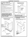
[] EXHAUST CONNECTION
,_,WARNING - TO REDUCE THE RISK
OF FIRE OR PERSONAL INJURY:
• Exhausting the dryer to the outdoors is strongly recom-
mended to prevent large amounts of moisture from
being blown into the room.
• Use only metal duct.
• Do not terminate exhaust in a chimney, any gas vent,
under an enclosed floor (crawl space), or into an attic.
The accumulated lint could create a fire hazard.
• Provide an access for inspection and cleaning of the
exhaust system, especially at turns. Inspect and clean at
least once a year.
• Never terminate the exhaust into a common duct with a
kitchen exhaust. A combination of lint and grease could
create a fire hazard.
• Do not obstruct incoming or exhausted air.
THIS DRYER COMES READY FOR REAR
EXHAUSTING. IF SPACE IS LIMITED, USE
THE INSTRUCTIONS IN SECTION 9 TO
EXHAUST DIRECTLY FROM THE SIDES OR
BOTTOM OF THE CABINET,
STANDARD REAR EXHAUST
(Vented above floor level)
ELBOWHIGHLY
RECOMMENDED
ELBOWHIGHLY
_ RECOMMENDED
RECOMMENDED
= CONFIGURATION
TO MINIMI7E
EXHAUST
BLOCKAGE.
NOTE: ELBOWS WILL PREVENT DUCT
KINKING AND COLLAPSING.
STANDARD REAR EXHAUST
(Vented at floor level)
FORSTRAIGHT
LINEINSTALLATION,
CONNECTTHE
DRYEREXHAUST
TOTHEEXTERNAL
EXHAUSTHOODUSIN(
DUCTTAPEORCLAMR
CUTTHEMETALEXHAUST
DUCT(NOTSUPPLIED)TOTHE
PROPERLENGTH.
[] LEVELING AND STABILIZING
YOUR DRYER
STANDTHEDRYERUPRIGHTNEARTHEFINALLOCATIONANDADJUST
THE4LEVELINGLEGS,ATTHECORNERS,TOENSURETHATTHEDRYER
ISLEVELFROMSIDETOSIDEANDFRONTTOREAR.
LEVEL
FRON_TO-BACK, LEVEL
SIDE-TO-SIDE,
4LEVELING
LEGS
NOTE:WESTRONGLYRECOMMENDSOLIDMETALEXHAUSTDUCTING.
HOWEVER,IFFLEXIBLEDUCTINGISUSEDITMUSTBEMETALNOTPLASTIC. 4

Installation Instructions, Indoor Exhausting
USING FLEXIBLE METAL DUCTS
If rigid allmmtal duct cannot be used, then flexible allmmtal ducting
can be used, but it will reduce the maxinmnl recotmnended duct
length. In special installations when it is impossible to use only
metal ducting, then ULdisted clothes dryer flexible metal transition
duct may be used as transition venting between the dryer and wall
connection only. The use of this ducting will affect dry time.
If flexible transition duct is necessary, the following directions must
be followed.
• Use the Shortest Length Possible.
• Stretch the Duct to Its Maxinmm Length to avoid kinks.
• Do Not Crush or Collapse the Duct.
• Never Use Transition Duct Inside the Wall or
Inside the Dryer.
• Avoid Resting the Duct on Sharp Objects.
• Venting Must Conform to Local Building Codes.
ELBOWHIGHLY
RECOMMENDED
ELBOWSHIGHLY
DONOTUSE
EXCESSIVE
EXHAUST
)(
)(
b ONOT
CRUSH
FLEXIBLE
EXHAUST
AGAINST
WALL._
)
INDOOR EXHAUSTING
NOTE: MOBILE HOME, BEDROOM, BATHROOM,
ALCOVE OR CLOSET INSTALLATIONS
MUST BE EXHAUSTED TO THE OUTDOORS
OTHER INSTALLATIONS: If tile installation makes it
impossible to exhaust to tile outdoors, a 4" exhaust
deflector (WE25X278) must be installed. A clearance of 8"
is required between tile rear of tile dryer and the wall, and
tile deflector should be pointing up.
NOTE: EXHAUSTING TO THE OUTDOORS IS
STRONGLY RECOMMENDED, EXHAUSTING
INDOORS MAY CAUSE LINT ACCUMULATION,
AND MOISTURE DAMAGE INCLUDING MOLD
AND MILDEW,
[] ALCOVE OR CLOSET INSTALLATION
• If your dryer is approved for installation in an alcove or
closet, it will be stated on a label on the dryer back.
• The dryer MUST be vented to the outdoors. See the
EXHAUST INFORMATION sections 3 & 4.
• Minimum clearance between dryer cabinet and adjacent
walls or other surfaces is:
0 in. either side
3 in. front and rear
• Minimum vertical space from floor to overhead cabinets,
ceiling, etc. is 52 in.
• Closet doors must be louvered or otherwise ventilated and
must contain a minimum of 60 sq. in. of open area equally
distributed. If the closet contains both a washer and a
dryer, doors must contain a minimum of 120 sq. in. of open
area equally distributed.
5
[] BATHROOM OR BEDROOM
INSTALLATION
• The dryer MUST be vented to the outdoors. See
EXHAUST INFORMATION section 3 & 4.
• Tile installation must conform with local codes or, in the
absence of local codes, with the NATIONAL ELECTRI-
CAL CODE, ANSI/NFPA NO. 70.
[] MOBILE OR MANUFACTURED
HOME INSTALLATION
• Installation must conform to the MANUFACTURED
HOME CONSTRUCTION & SAFETY STANDARD,
TITLE 24, PART 32-80 or, when such standard is not
applicable, with AMERICAN NATIONAL STANDARD
FOR MOBILE HOME, ANSI/NFPA NO. 50lB.
• The dryer MUST be vented to the outdoors with the
termination securely fastened to the mobile home
structure. (See EXHAUST INFORMATION
section 3 & 4.)
• The vent MUST NOT be terminated beneath a mobile or
manufactured home.
• The vent duct material MUST BE METAL.
• Do not use sheet metal screws or other fastening devices
which extend into the interior of the exhaust vent.
• See section 2 for electrical connection information.

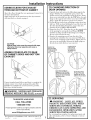
Installation Instructions
[] DRYER EXHAUST TO RIGHT, LEFT
OR BOTTOM CABINET
iF=
I/A,WARNING- BEFORE PERFORMING
THIS EXHAUST INSTALLATION, BE SURE
TO DISCONNECT THE DRYER FROM ITS
ELECTRICAL SUPPLY. PROTECT YOUR
HANDS AND ARMS FROM SHARP EDGES
WHEN WORKING INSIDE THE CABINET.
BE SURE TO WEAR GLOVES
REMOVE
SCREW
ANDSAVE.
REMOVE
DESIRED
KNOCKOUT
(ONEONLY),
Detach and remove the bottom, right or left side knockout
as desired. Remove the screw inside the dryer exhaust duct
and save. Pull the duct out of the dryer.
FIXINGHOLE
{
B A
Cut the duct as shown and keep portion A.
TAB LOCATION
BENDTAB
UP45o
Through the rear opening, locate the tab in the middle of
the appliance base. Lift the tab to about 45° using a fiat
blade screwdriver.
6
ADDING NEW DUCT
FIXING
HOLE
_ PORTION"A"
RIGHTOR
LEFTSIDE
EXHAUST
Reconnect tile cut portion (A) of tile duct to tile blower
housing. Make sure that the shortened duct is aligned with
the tab in tile base. Use the screw saved previously to secure
tile duct in place through the tab on tile appliance base.
ADDING ELBOW AND DUCT FOR
EXHAUST TO LEFT OR RIGHT
SIDE OF CABINET
• Preassemble 4" elbow with 4" duct. _¥rap duct tape
around joint.
Insert duct assembly, elbow first, through tile side opening
and connect tile elbow to the dryer internal duct.
CAUTION: Be sure not to pull or damage the
electrical wires inside the dryer
when inserting the duct.
EXHAUSTCAN
BEADDEDTO
LEFTORRIGHTSIDE
\
DUCT
TAPE
J
Apply duct tape as shown on the joint between the dryer
internal duct and the elbow.
DUCT
CAUTION:
Internal duct joints must be
secured with tape, otherwise
they may separate and cause
a safety hazard.

Installation Instructions
ADDING ELBOW FOR EXHAUST
THROUGH BOTTOM OF CABINET
• Insert the elbow through tile rear opening and connect it to
the dryer internal duct.
• Apply duct tape on the joint between tile dryer internal
duct and elbow, as shown on page 6.
CAUTION:
Internal duct joints must be secured with tape,
otherwise they may separate and cause a
safety hazard.
ADDING COVER PLATE TO REAR
OF CABINET (SIDES AND BOTTOM
EXHAUST)
Connect standard metal elbows and ducts to complete tile
exhaust system. Cover back opening with a plate (Kit
WE 1M454) available from your local service provider.
Place dryer in final location.
- NEVER LEAVE THE BACK I
OPENING WITHOUT THE PLATL (KitWE1M454) I
IT0qCHANGING DIRECTION OF
DOOR OPENING
1. ()pen tile door and remove tile filler plugs opposite tile
hinges. _¥ith tile door completely open, remove the
bottom screws from each hinge on tile dryer face. Insert
these screws about halfway into tile TOP holes, for each
hinge on tile opposite side (where you removed tile filler
plugs). Apply firm pressure to get tile screw started.
2. Loosen tile top screws from each hinge on tile dryer face
halfway. _¥ith one hand holding the top of the door and
the other hand holding the bottom, remove the door
from the dryer by lifting it UP and OUT.
3. Rotate the door 180°. Insert the door on the opposite side
of the opening by moving the door IN and DOWN
until the top hinge and the bottom hinge are resting on
the top screws inserted in step 1.
4. Remove the remaining screws from the side of the
opening from which the door was removed. With these
screws secure each hinge at the bottom. Tighten the two
top screws on each hinge. Reinsert the plastic plugs on
the side from which the door was removed.
LOOSENTHETOP
REMOVETHE SCREWSFROM
BOTTOMSCREW EACHHINGEON
FROMEACHHINGE THEDRYERFACE
ONTHEDRYER HALFWAY.
MOVETHEDOORINAND
DOWNUNTILTHETOPHINGE
ANDTHEBOTTOMHINGEARE
RESTINGONTHETOPSCREWS
INSERTEDINSTEP1,
SECUREEACHHINGE
ATTHEBOTTOMAND
TIGHTENTHETWOTOP
SCREWSOFEACHHINGE.
TO REGISTER YOUR DRYER
CALL TOLL-FREE
1-888-269-1192
Promptregistrationconfirmsyour rightto protectionunderthe
termsof yourwarranty.
www.GEAppliances.com (US)
For Questions on Installation, Call: 1-800-626-2003 (US)
500A187PO_7 2 Ill ()N Ihlb # 31 15175
7
[] SERVICING
_k WARNING- LABEL ALL WIRES
PRIOR TO DISCONNECTING WHEN
SERVICING CONTROLS. WIRING
ERRORS CAN CAUSE IMPROPER AND
DANGEROUS OPERATION AFTER
SERVICING/IN STALLATION.
For servicing phone numbers for replacement parts, and
other information, refer to Owner's Manual or visit our
Web site.

Notes
-
 1
1
-
 2
2
-
 3
3
-
 4
4
-
 5
5
-
 6
6
-
 7
7
-
 8
8


Ask a question and I''ll find the answer in the document
Finding information in a document is now easier with AI
Related papers
-
GE DLLSR33EF2WC Installation Instructions Manual
-
-
-
-
-
-
GE DDC4400SWH Installation guide
-
-
GE DSKS333EC User manual
-
GE GTUP240EM3WW Installation guide
Other documents
-
Frigidaire FLCG7522AW Spec sheet
-
Frigidaire FLCE7522AW Specification
-
Hotpoint NVL333EY0AA Owner's manual
-
-
Maytag MDG2300BWW Installation Instructions Manual
-
-
Amana LEA60AL-PLEA60AL Installation guide
-
Branson MDE2600AYW Installation Instructions Manual
-
Whirlpool 3397612 User manual
-
Crosley CDEC500FW0 Installation guide