Page is loading ...

200-0217
DECEMBER 2005
7116 Beatty Dr
Mission, BC V2V 6B4
Canada
Installer: Please leave this manual with the appliance owner for future reference
Optima 3600
Optima 3600
Direct Vented
Top or Rear Vent
Gas Room Heater
For use with natural gas or propane*
This appliance may be installed in an
aftermarket permanently located,
manufactured home (USA only) or mobile
home, where not prohibited by local codes.
This appliance is only for use with the type
of gas indicated on the rating plate. This
appliance is not convertible for use with
other gases, unless a certified kit is used.
*Conversion kit required for Propane use
WARNING: If the information in this manual is
not followed exactly, fire or explosion may result
causing property damage, personal injury or loss
of life.
Do not store or use gasoline or other flammable
vapors and liquids in the vicinity of this or any
other appliance.
WHAT TO DO IF YOU SMELL GAS:
∗ Do not try to light any appliance.
∗ Do not touch any electrical switch; do not use
any phone in your building.
∗ Immediately call your gas supplier from a
neighbor’s phone. Follow the gas supplier’s
instructions.
∗ If you cannot reach your gas supplier, call the
fire department.
Installation and service must be performed by a
qualified installer, service agency or the gas
supplier.
USERS’ INSTALLATION
OPERATION AND
MAINTENANCE MANUAL


Thank you for purchasing the Optima 3600 Zero Clearance Direct Vented Fireplace
Gas Heater.
The Optima 3600 is one of the most advanced direct vented zero clearance gas
heaters on the market. It is designed using the latest technology and manufactured to
the highest quality.
Some of the many features are:
∗ True Zero Clearance No standoffs required.
∗ Heater Classification It is classified as a heating appliance. Therefore, it can be
operated continuously for zone heating.
∗ High Efficiency It has high efficiency; therefore, less expensive to operate.
∗ Adjustable Flame The flame aesthetics and heat output can be adjusted to suit
the owner’s moods and heating needs.
∗ Solid Construction It is constructed mainly of satin coated, aluminized and
galvanized steel for long life and durability.
Please read the manual carefully prior to installation and operation of the
appliance. Proper installation, operation and maintenance of the appliance will
provide you with many years of enjoyment.
We recommend you record the following information:
INTRODUCTION
Fireplace Model Number: ODV - 3600 Serial Number:
Date of Installation:
Type of Gas Used by the Fireplace: Natural Gas Propane
Dealer’s Name & Address:
Dealer’s Phone Number:

General Information 6
Appliance Dimensions 7
Installation Clearances 8
Electrical Connections, Fan System 9
Glass Door Removal 10
Log Placement 11
Installation Instructions 15
Optional Wall Switch or Thermostat 18
Top / Rear Vent Conversion 19
Allowable Termination Locations 20
Approved Vent Components 21
Venting Components - Parts List 22
Venting - Rear Vent 24
Venting - Top Vent 25
Horizontal Venting Instructions 26
Vertical Venting Instructions 27
Operation Instructions - Safety Information 28
Operation Instructions - Start Up & Shut Down Procedures 29
Maintenance 30
Troubleshooting 31
Servicing 33
Important Information 35
Replacement Parts List 36
Archgard Warranty 38
Warranty Registration Card 40
Caution & Safety Information 5
Page
TABLE OF CONTENTS

Optima 3600
5
Due to high temperatures, the appliance should be located out of traffic and away
from furniture and draperies.
Children and adults should be alerted to the hazards of high surface temperature
and stay away to avoid burns or clothing ignition.
Young children should be carefully supervised when they are in the same room as
the appliance.
Clothing or other flammable material should not be placed on or near the
appliance.
Any parts removed or opened for servicing of the appliance must be properly
replaced prior to operating the appliance.
The appliance must be inspected before use and at least annually by a qualified
service person. More frequent cleaning maybe required due to excessive lint from
carpeting, bedding material, etc. It is imperative that the control compartments,
burners and circulating air passageways for the appliance be kept clean.
Venting terminals shall not be recessed into a wall or siding.
This gas appliance must not be connected to a chimney flue serving a separate
solid fuel burning appliance.
FOR YOUR SAFETY - Do not install or operate your Archgard Optima 3600 Direct
Vent Gas Fireplace without reading and understanding this manual. Any
installation or operational deviation from this instruction manual voids the
Archgard Industries Warranty and may prove hazardous.
This appliance must be installed by a qualified gas installer and the installation
must conform to the installation codes.
Provide adequate clearance around air openings of the appliance.
Never obstruct front openings.
Provide adequate clearances for proper operation and servicing of the appliance.
This appliance must be properly connected to an approved venting system and
must not be connected to a chimney flue serving a separate solid fuel burning
appliance.
CAUTION / SAFETY INFORMATION

Optima 3600
6
HIGH ALTITUDE INSTALLATION
When installing this appliance beyond 4500 ft. (1372 m) above sea level, the appliance must be properly
de-rated and installed according to local codes, in the absence of local codes, with the current National
Fuel Gas Code, ANSI Z223.1/ NFPA 54, in the US or Installation Code, CSA-B149.1, in Canada.
Natural Gas (NG) Propane (LP)
Manifold Pressure
1.7-3.5 in. W.C. (0.4-0.9 kpa) 6.5-10.0 in. W.C. (1.6-2.5kpa)
Min. Supply Pressure for
Purpose of Input Adjustment
4.5 in. W.C. (1.1 kPa) 11.0 in. W.C. (2.7 kPa)
Orifice Size
#43 DMS #54 DMS
Nominal Input Rating
17,000 - 24,000 BTU/hr
(4.98 –7.03 kW)
19,000 -24,000 BTU/hr
(5.57 - 7.03 kW)
Altitude
0 - 4,500 ft. (0 - 1372 m) 0 - 4,500 ft. (0 - 1372 m)
Primary Air Opening
closed 25% open
SPECIFICATIONS
This appliance is tested and certified to the following US and Canadian gas appliance standards.
- ANSI Z21.88b-2003 / CSA 2.33b-2003 Vented Gas Fireplace Heaters,
- CAN/CGA-2.17-M91 Gas-Fired Appliance fo Use at High Altitudes
Please contact Archgard Industries Ltd., if you have any questions regarding the certification of this
appliance.
INSTALLATION CODES
This appliance must be installed by a qualified gas appliance installer. The installation must conform with
the local codes or, in the absence of local codes, with the current National Fuel Gas Code, ANSI Z223.1/
NFPA 54, in the US or Installation Code, CSA-B149.1, in Canada. Electrical connections and grounding
must be in accordance with local codes, if any, if not, follow the current CAN/CSA C22.1 in Canada and
ANSI/NFPA 70 in the US. This appliance is certified for installation in a bedroom or a bedsitting room.
This appliance is only for use with the type of gas indicated on the rating plate and may be installed in an
aftermarket, permanently located, manufactured (mobile) home where not prohibited by local codes. See
owner’s manual for details. This appliance is not convertible for use with other gases, unless a certified kit
is used. This appliance must be installed in accordance with the current Standard CAN/CSA Z240 1411,
Mobile Housing, or with the Manufactured Home Construction and Safety Standard Title 24 CFR, Part
3280, or when such a standard is not applicable, ANSI/NCSBCS A225.1/NFPA 501A, Manufactured
Home Installations Standard. Only for direct discharge without duct connection. This appliance must be
direct vented using listed Simpson Dura-Vent components.
GENERAL INFORMATION
APPLIANCE CERTIFICATION

Optima 3600
7
APPLIANCE DIMENSIONS

Optima 3600
8
INSTALLATION CLEARANCES
Mantle Height from Floor (B) Mantle Depth (A)
40" (1016 mm) 12" (305 mm)
39" (991 mm) 10-5/16" (262 mm)
38" (965 mm) 8-9/16" (217 mm)
37" (940 mm) 6-7/8" (175 mm)
36" (914 mm) 5-1/8" (130 mm)
35" (889 mm) 3-7/16" (81 mm)
34" (864 mm) 1-11/16" (43 mm)
Sidewall clearance (C) = 6" (305 mm) from edge of unit
Unexposed Back & Sidewalls = 0"
Internal Ceiling = 40" (1016 mm) from floor
Floor = 0"
Mantle = See Chart
Vertical Vent = 1” (25 mm) to outside surface
Horizontal Vent = 1” (25 mm) to outside side and bottom surface
Horizontal Vent = 2” (50 mm) to outside top surface.
Note: Check local codes for floor requirements. This fireplace is suitable for installation
on a combustible surface.
MANTLE & SIDEWALL CLEARANCES
CORNER FRAME DIMENSIONS

Optima 3600
9
ELECTRICAL CONNECTIONS, FAN SYSTEM
WARNING: Before starting, make certain the power supply is turned OFF.
The Optima 3600 comes complete with a temperature activated fan and rheostat installed and
wired to an internal junction box. The heat sensor is factory set to close the circuit to the fan
speed control at 110
0
F (43
0
C) and will turn off the fan when the temperature falls below 80
0
F
(27
0
C).
Have a qualified electrician run a 120VAC supply line to the lower right side of the fireplace
before installing the appliance. There should be 18” (460mm) of the supply line free for ease of
connection to the appliance. Connect the electrical supply line to the appliance at the same
time the gas line is being connected to the appliance.
NOTE: This appliance, when installed, must be electrically grounded in accordance with local
codes or, in the absence of local codes, with the National Electrical Code, ANSI/NFPA 70, or
the Canadian Electrical code, CSA C22.1.
Remove or open the bottom (louver) grill. Remove the junction box cover. Run the line into the
right side of the appliance through the hole in the rear of the junction box and hold with a
standard ⅞” (22 mm) clamp. Connect the (black) supply conductor to the free black conductor
from the speed controller with a marrette type wire connector. Connect the ‘neutral’ white
supply conductor to the free white conductor from the fan with a marrette-type wire connector.
Connect the ‘ground’ (green or bare) conductor to the ground screw in the junction box.
Replace the junction box cover. A BX connector or other suitable approved wiring strain relief
must be installed on the junction box.
WIRING DIAGRAM
MO
SPEED
CONTROL
110ºF (43ºC) N.O.
THERMAL SNAP
SWITCH
CONVECTION BLOWER
LINE
GROUND
NEUTRAL
To Appliance Body
120 VAC
white
black
SPEED
CONTROL
LINE
GROUND
NEUTRAL
110ºF (43ºC) N.O.
THERMAL SNAP
SWITCH
CONVECTION BLOWER
black white black
green

Optima 3600
10
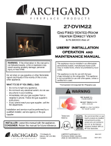
Removing the Glass Door
❖ Remove the top & bottom louvers (or optional front).
❖ Unhook the door latches found on the bottom of the firebox - shown below
❖ Carefully lift and remove the door.
❖ Place the door at a safe location where it cannot be scratched or damaged.
❖ If the glass door is damaged, it must be replaced with another glass door certified for this
appliance.
❖ Replacement glass doors are available through your Archgard dealer (See Replacement
Parts page 36)
Replacing the Glass Door
❖ Check the condition of the glass and the gasket before installing door.
❖ Carefully hook the door onto the 4 tabs on the top of the firebox. (2 left, 2 right)
❖ Connect the door latches, at the bottom of the door, by pulling forward on the 2 bottom
latches and hooking them over the lower door frame flange.
❖ Install the top & bottom louvers (or optional front).
If the glass has been damaged contact your dealer and replace the door assembly with a new
assembly provided by your dealer.
WARNING:
❖ Do not attempt to remove the glass door when the appliance is hot.
❖ Do not abuse the glass door.
❖ Do not strike or slam the glass.
GLASS DOOR REMOVAL
TOP LATCH
BOTTOM LATCH

Optima 3600
11
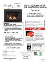
LOG PLACEMENT
The Archgard pan burner and fiber logs are designed to give a realistic fire package, and are
created to maintain their appearance from the day they were originally installed. Care must be
given when first installing the logs and when removed for servicing, as they can be damaged or
broken if not handled properly.
After opening the log set package, inspect the logs to ensure that no damage has occurred
inside the package. Please report any damage immediately to your Authorized Archgard
Dealer.
Gas and vent connections must be made before installing the logs and embers on the pan
burner.
NOTE: Improper placement of logs may cause sooting on the internal parts and glass, and will
not be covered under warranty. Do not use broken or damaged logs.
WARNING: Failure to position the parts in accordance with these diagrams or failure to
use only parts specifically approved with this appliance may result in property damage or
Refer to the pictured instructions on the following pages that will show you how to correctly
place the logs. The bottom of each log has a code stamped on it that can be used as a refer-
ence to help locate the correct log.
IMPORTANT: Pins & holes must be aligned with logs & burner.
LOCATOR PINS ON BURNER SHOWN
LOCATOR PINS

Optima 3600
12
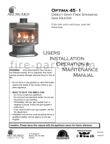
STEP 1 - PLACE REAR LOG (#146) ON PINS AND BURNER AS SHOWN
LOG PLACEMENT - CONTINUED
STEP 2 - PLACE LEFT LOG (#144) ON PIN AND LOG AS SHOWN
144
146

Optima 3600
13
STEP 3 - PLACE FRONT LOG (#147) ON PINS AND BURNER AS SHOWN
STEP 4 - PLACE RIGHT LOG (#145) ON PIN AND LOGS AS SHOWN
LOG PLACEMENT - CONTINUED
147
145

Optima 3600
14
STEP 5 - PLACE RIGHT LOG (#148) AND EMBERS AS SHOWN
LOG PLACEMENT - CONTINUED
147
146
144 145
148
STEP 6 - PLATINUM EMBERS SHOULD BE PLACED ON BURNER AS SHOWN

Optima 3600
15
PRECAUTIONS
❖ This appliance must be installed by a qualified gas installer and the installation conform to
the installation codes.
❖ This appliance needs fresh air for safe operation and must be installed so there are
provisions for adequate ventilation air. Provide adequate clearance around air openings of
the appliance. Never obstruct front openings.
❖ Provide adequate clearances for proper operation and servicing of the appliance.
❖ This appliance must be properly connected to a venting system.
❖ This appliance must NOT be connected to a chimney flue serving a solid-fuel appliance.
LOCATING GAS FIREPLACE
The venting system of this appliance must be installed in any location that is free of plumbing,
electrical wiring and heating or air conditioning ducts. Select a location that is accessible for
venting. See the ALLOWABLE TERMINATION LOCATIONS - page 20, in this manual. When
the appliance is installed directly on carpeting, vinyl tile or other combustible material, other than
wood flooring, the appliance must be installed on a metal or wood panel extending the full width
and depth of the appliance.
1. Establish a suitable vent termination location. (See ALLOWABLE TERMINATION
LOCATIONS - page 20)
2. In heavy snowfall areas make sure vent termination is located where it can not be blocked by
snowfall or snow from snow removal equipment.
3. Locate vent termination away from plants, bushes or any other object on or near the vent
termination that will interfere or obstruct the air flow around it.
4. DO NOT recess vent termination into walls, sidings or planters.
5. Vent terminations located below 7 ft (2130 mm) from grade level or anywhere that it is a burn
hazard to the public, such as patios and balconies, must be protected with an approved
termination cage.
INSTALLATION INSTRUCTIONS
VENT TERMINATION LOCATION

Optima 3600
16
Have your gas supplier or a qualified gas fitter run a gas supply line into the gas fireplace.
The line must be properly sized and fitted according to the installation codes. Upstream of
the supply connection, the fitter shall provide a manual shut-off valve.
CAUTION: The appliance and its individual shutoff valve must be disconnected from
the gas supply piping system during any pressure-testing of that system at test pressures
in excess of ½ psig (3.5 kPa). The appliance must be isolated from the gas supply piping
system by closing its individual manual shutoff valve during any pressure-testing of the
gas supply piping system at test pressures equal to or less than ½ psig (3.5 kPa). Failure
to do so will damage the appliance’s gas valve. Such damage is not cover by the
manufacturer’s warranty.
INSTALLATION INSTRUCTIONS
1. Open the lower grills.
2. The pressure test taps are located on the valve. The taps are located in the gas valve
front face. The inlet is marked ‘IN’ and the outlet is marked ‘OUT’. (See Fig.1)
3. Loosen the set screw inside the tap with a ⅛” (3 mm) wide flat screw driver.
4. Connect a ¼” (6 mm) rubber tube to the tap post and a manometer.
5. Verify the readings obtained are within specs (as shown on the appliance rating plate)
6. Be sure to tighten the set screw inside the tap after you are finish taking pressure
readings.
7. Check for leaks.
CHECKING INLET & OUTLET GAS PRESSURE
Fig.1
GAS CONNECTIONS

Optima 3600
17
INSTALLATION INSTRUCTIONS
The minimum permissible gas supply pressure is 4.5 in. w.c. (1.12 kPa) for natural gas and 11.0 in. w.c.
(2.74 kPa) for propane. Maximum gas supply pressure should never exceed 14.0 in. w.c. (3.48 kPa) or ½
psi. for both natural gas and propane. BE SURE TO TIGHTEN THE PRESSURE TAP SET SCREW
AFTER CHECKING THE PRESSURE.
Before connecting the appliance to the gas supply line, double check that the appliance you have
purchased is designed for the gas type you are using. The gas type markings are located on the
certification label and also on the appliance’s gas valve.
Adequate clearance for proper installation and checking of the gas connections must be provided. All gas
connections must be checked for gas leaks.
GAS CONNECTIONS - CONTINUED
CHECKING & ADJUSTING PILOT
CONVERTIBLE PILOT ORIFICE
The pilot assembly is convertible to the
type of gas being used, simply unscrew
the body by using a 7/16” (11 mm)
wrench turn ¼open then push the small
metal tab across to the other side of the
body and retighten. Call your local
Authorized Archgard Dealer to
purchase the correct fuel conversion
kit for your gas appliance.
7/16” (11 mm)
WRENCH
(HERE)
The pilot flame should have the
characteristic as shown in the illustration
to the right. The flame should not have
yellow tips but should engulf the
thermocouple and thermopile. It can be
adjusted be turning the screw marked
“pilot” on the control valve.
Thermopile
Burner Ports
Electrode
Thermocouple
AIR SHUTTER ADJUSTMENT
CAUTION: MUST BE DONE WHEN APPLIANCE IS COLD.
Remove / open lower louvre, slightly loosen the wing nut
located under the firebox near the centre at the rear. Push
back lever for cleaner burn; tab forward for a richer burn.
SHOWN FULLY CLOSED AND PROPERLY SET FOR
NATURAL GAS. PUSH BACK ¼ FOR PROPANE GAS.

Optima 3600
18
If a wall mounted switch or a wall mounted thermostat is desired, Archgard recommends that
the device be wired as shown in Fig 1. This will allow the original on/off rocker switch to be
used incase the device that is mounted to the wall is inoperable.
Note: Archgard Industries does not manufacture, or sell any wall switch or wall thermostat, and
will not extend warranty to them.
OPTIONAL WALL SWITCH OR THERMOSTAT
Thermostat / wall switch wire table
Recommended Maximum Lead Length
for two wires
Wire Size Max. Length
14 GA. 50 Ft. (15.24 M)
16 GA. 32 Ft. (9.75 M)
18 GA. 20 Ft. (6.9 M)
20 GA. 12 Ft. (3.65 M)
22 GA. 9 Ft. (2.74 M)
Fig. 1
B
A
C
D
SUPPLY TUBE
THERMOCOUPLE LEAD
WIRE TO
PIEZO
(SPARKER)
OPTIONAL REMOTE,
WALL SWITCH OR
WALL THERMOSTAT
A ELECTRODE
B THERMOPILE
C PILOT CAP
D THERMOCOUPLE
PILOT ASSEMBLY
VALVE CONNECTION for MILLIVOLT VALVE
ON / OFF SWITCH
OFF
O
N
P
I
L
O
T
L
O
H
I
CAUTION: DO NOT CONNECT ANY AC VOLTAGE TO THE GAS VALVE.

Optima 3600
19
The appliance is easily converted from top vent
to rear vent.
The steps for converting are as follows:
1. Remove the top vent outer shell cover (#1)
2. Remove the top vent heat shield cover (#2)
3. Remove the outer collar assembly (#3)
4. Remove the exhaust collar assembly (#4)
5. Rotate the exhaust collar assembly and the
outer collar assembly to the rear vent
configuration and reinstall.
6. Install rear vent heat shield cover (#5)
7. Install rear vent outer shell cover (#6)
5
1
4
3
6
4
3
2
TOP / REAR VENT CONVERSION

Optima 3600
20
Canadian Installations
(1)
US Installations (2) Canadian Installations (1) US Installations (2)
A= Clearance above grade,
veranda, porch, deck, or balcony
12 inches (30 cm) 12 inches (30 cm) J= Clearance to non-mechanical air
supply inlet to building or the
combustion air inlet o any other
appliance
12 inches (30 cm) 9 inches (23 cm)
B= Clearance to window or
door that may be opened
12 inches (30 cm) 12 inches (30 cm) K= Clearance to a mechanical
air supply inlet
6 feet (1.83 m) 3 feet (91 cm) above if
within 10 feet (3 m) hori-
zontally
C= Clearance to permanently
closed window
12 inches (30 cm) 12 inches (30 cm) L= Clearance above paved
sidewalk or paved driveway
located on public property
7 feet (2.13 m) + *
D= Vertical clearance to
ventilated soffit located
above the terminal within a
horizontal distance of 2 feet
(61 cm) from the center line
of the terminal
21 inches from center of
termination (53 cm)
21 inches from center
of termination (53 cm)
M= Clearance under veranda,
porch, deck, or balcony
12 inches (30 cm) ++ *
E= Clearance to unventilated soffit 21 inches from center
of termination (53 cm)
21 inches from center
of termination (53 cm)
F= Clearance to outside corner 0" 0"
G= Clearance to inside corner 12-3/4" to center of
termination (32 cm)
12-3/4" to center of
termination (32 cm)
H= Clearance to each side of
center line extended above
meter/regulator assembly
3 feet (91 cm) within a
height 15 feet (4.5 m)
above the
meter/regulator assembly
*
L= Clearance to service
regulator vent outlet
6 feet (183 cm) *
(1) In accordance with the current CSA B149.1, National Gas and Propane Installation Code
(2) In accordance with the current ANSI Z223.1/NFPA 54, National Fuel Gas Code
(+) A vent shall not terminate directly above a side walk or paved driveway that is located be-
tween
two single family dwellings and serves both dwellings
(++) Permitted only if veranda, porch, deck, or balcony is fully open on a minimum of two sides
beneath the floor.
(*) For clearances not specified in ANSI Z223.1/NFPA 54 or CSA B149.1, “Clearances must
be in accordance with local installation codes and the requirements of the gas supplier.”
ALLOWABLE TERMINATION LOCATIONS
/