Harbor Freight Tools Pipe/Tubing Notcher Owner's manual
- Category
- Power tools
- Type
- Owner's manual
This manual is also suitable for

PIPE/TUBE NOTCHER
42324
ASSEMBLY & OPERATING INSTRUCTIONS
Visit our website at: http://www.harborfreight.com
Read this material before using this product.
Failure to do so can result in serious injury.
SAVE THIS MANUAL.
Copyright
©
2000 by Harbor Freight Tools
®
. All rights reserved. No portion of this manual or any artwork
contained herein may be reproduced in any shape or form without the express written consent of Harbor Freight
Tools. Diagrams within this manual may not be drawn proportionally. Due to continuing improvements, actual
product may differ slightly from the product described herein. Tools required for assembly and service may not
be included.
For technical questions or replacement parts, please call 1-800-444-3353.

SPECIFICATIONS MODEL # 42324 PIPE NOTCHER
FEATURES OF THIS PRECISION PIPE NOTCHER
This precision pipe notcher is a useful xture for your drill press, allowing you to make round 1.
cuts in pipes and tubing of various shapes at any angle from 0-60 degrees.
Sturdy and durable steel frame holds your workpieces rigid during operation.2.
Base is adaptable to any worktable, and is especially suited to be mounted on drill press 3.
tables.
The base may be swiveled and rotated, which in conjunction with the adjustable pipe holder 4.
makes cutting compound angles very easy.
Works with any standard drill press, and is adaptable to a large variety of round cutters, hole 5.
saws, and milling bits.
SAVE THIS MANUAL
You will need this manual for the safety warnings and cautions, assembly instructions, operating
procedures, maintenance procedures, trouble shooting, parts list, and diagram. Keep your invoice
with this manual. Write the invoice number on the inside of the front cover. Keep both this manual
and your invoice in a safe, dry place for future reference.
Page 2 SKU # 42324
NOTICE
The Warnings, Cautions, and Instructions discussed in this instruction manual cannot
cover all possible conditions and situations that may occur. It must be understood by
the operator that common sense and caution are factors which cannot be built into
this product, but must be supplied by the operator.
Warning: When using this pipe notcher with any powered tool, observe all
safety precautions relevant to that equipment. Refer to the owner’s manual of
the power equipment for safe practices in the use of attachments.
Construction
.224” Chrome Plated Steel Frame
.149” Black Oxide Steel Clamp
.485” Handle/Clamp Screw
Machined Aluminum Spindle Support
Spindle Dimensions 3/4” with 1/2”-20 thread
Spindle Adapter 1/2” to 5/8”
Angle Adjustment 0-60° Left
Mounting Bracket Adjustable
Net Weight 9.8 Lbs.

SAFETY WARNING & CAUTIONS
KEEP WORK AREA CLEAN. Cluttered areas invite injuries.1.
OBSERVE WORK AREA CONDITIONS. Do not use tools in damp, wet, or poorly lit locations. 2.
Don’t expose to rain. Keep work area well lit. Do not use electrically powered equipment in the
presence of ammable gases or liquids.
KEEP CHILDREN AWAY. Children must never be allowed in the work area. Do not let them 3.
handle machines, tools, or equipment.
STORE IDLE EQUIPMENT. When not in use, tools must be locked up in a dry location to 4.
inhibit rust. Always lock up tools and keep out of reach of children.
DO NOT FORCE THE TOOL. It will do the job better and more safely at the rate for which 5.
it was intended. Do not use inappropriate attachments in an attempt to exceed the tool’s
capacities.
USE THE RIGHT TOOL FOR THE JOB. Do not use a tool for a purpose for which it was not 6.
intended.
DRESS PROPERLY. 7. Do not wear loose clothing or jewelry, as they can be caught in moving
parts. Non-skid footwear is recommended. Wear restrictive hair covering to contain long hair.
Always wear appropriate work clothing.
USE EYE, EAR8. AND BREATHING PROTECTION. Always wear ANSI approved impact safety
goggles if you are producing metal lings or wood chips. Wear an ANSI approved dust mask
or respirator when working around metal, wood, and chemical dusts and mists. Use ANSI
approved ear protection when working in a loud or noisy environment.
DO NOT OVERREACH. Keep proper footing and balance at all times. Do not reach over or 9.
across running machines.
MAINTAIN TOOLS WITH CARE. Keep tools sharp and clean for better and safer 10.
performance. Follow instructions for lubricating and changing accessories. Inspect power cord
periodically, and if damaged, have it repaired by an authorized technician.
STAY ALERT. Watch what you are doing. Do not operate this machine when you are tired.11.
DO NOT OPERATE MACHINERY WHILE UNDER THE INFLUENCE OF ALCOHOL, 12.
DRUGS, OR PRESCRIPTION MEDICINES.
CHECK FOR DAMAGED PARTS. Before using any tool, any part that appears damaged 13.
should be carefully checked to determine that it will operate properly and perform its intended
function. Check for alignment and binding of moving parts, any broken parts or mounting
xtures, and any other condition that may affect proper operation.
REPL14. ACEMENT PARTS AND ACCESSORIES. When servicing, use only identical
replacement parts, which are available from Harbor Freight Tools. Use of any other parts will
void the warranty.
Page 3 SKU # 42324
WARNING: When using shop equipment, basic safety precautions should
always be followed to reduce the risk of personal injury and hazards.

Page 4 SKU # 42324
ASSEMBLY AND SET UP
NOTE: This notcher is designed for use with threaded, metal-cutting hole saws.
Basic Assembly and Set-up.
The Spindle (#7) is shipped in the reverse position. Remove it and re-insert it in the correct 1.
position prior to using the tool.
Your pipe notcher must be mounted to your drill press table, using the adjustable angle joint 2.
plate (#17). Depending on the conguration of your drill press table, you may use T-bolts, car-
riage bolts or standard machine bolts, washers and nuts. Hardware is not supplied.
After mounting, be sure that the spindle travels smoothly without binding against the bushings 3.
(#5). Any undue friction will cause excessive wear of the bushings.
The angle of the notcher can be adjusted by loosening the bolts (#16) that adjust the adjust-4.
able angle joint plate, and moving the assembly as necessary.
For side to side adjustments, loosen the bolts (#15) that hold the adjustment plate to the body 5.
(#13).
When installing the hole saw, check rst to see if its arbor is 1/2” or 5/8”. The threads on the 6.
spindle are for 1/2”, however, there is an adapter (#3) for 5/8” models that can be screwed on
over the 1/2” threads. You may need to use the adapter washer (#4) to assure a good, secure
t.
To install a saw blade or bit, rst x the spindle in place with thee lockijng pin (#14). 7. Do not
use locking pliers or clamps to hold the spindle, as this will cause damage. Slide the locking
pin through the hole in the side of the spindle support (#6) and through the spindle. Install the
blade, then remove the locking pin.
WARNING: Make sure the pin is removed prior to engaging the drill.
OPERATION
Using the Pipe Notcher Fixture.
Insert the tubing you wish to cut in the clamp assembly (#1), underneath the inverted “V”. The 1.
inverted “V” feature of the clamp will hold your tubing (up to 2” long) in place. Do not insert the
tubing more than half of its length. When cutting in severe angles, only insert the tubing far
enough to start the cut. Secure the tubing in place using the handle/clamp screw assembly
(#2).
Set the speed of your drill press to approximately 500 rpm for most materials. When cutting 2.
thin wall, hard alloy tubing such as chrome-moly, higher speeds will be required. When cutting
softer, coarser materials, slower speeds may be ideal. SUGGESTION: Practice on scrap
material before making cuts on your work material.
As you work, lubricate both the hole saw and the bushings with cutting oil to extend service 3.
life.
When doing severe angle cuts with large diameter tubing, you will need to put the spindle 4.
support in its uppermost position in order to accomodate its size. However, you should always
position the spindle support as low as possible to preserve accuracy. To move the spindle
support, simply loosen the two bolts (#16) that afx it to the body, reposition, and secure the
bolts.
To adjust the angle of the clamp, loosen the bolts (#15) that secure it to the body, reposition to 5.
the angle you desire according to the angle indicator (#10), and retighten the bolts.
When the tube is clamped in the notcher and the angle is properly set, you can proceed to cut 6.
the workpiece.
To remove the blade or bit, shut off the drill press, insert the locking pin into the spindle sup-7.
port, and remove the bit.

Page 5 SKU # 42324
PLEASE READ THE FOLLOWING CAREFULLY
THE MANUFACTURER AND/OR DISTRIBUTOR HAS PROVIDED THE PARTS DIAGRAM IN THIS
MANUAL AS A REFERENCE TOOL ONLY: NEITHER THE MANUFACTURER NOR DISTRIBUTOR
MAKES ANY REPRESENTATION OR WARRANTY OF ANY KIND TO THE BUYER THAT HE
OR SHE IS QUALIFIED TO MAKE ANY REPAIRS TO THE PRODUCT OR THAT HE OR SHE IS
QUALIFIED TO REPLACE ANY PARTS OF THE PRODUCT: IN FACT THE MANUFACTURER A
ND/OR DISTRIBUTOR EXPRESSLY STATES THATALL REPAIRS AND PARTS REPLACEMENTS
SHOULD BE UNDERTAKEN BY CERTIFIED AND LICENSED TECHNICIANS AND NOT BY THE
BUYER. THE BUYER ASSUMES ALL RISK AND LIABILITY ARISING OUT OF HIS OR HER REPAIRS
TO THE ORIGINAL PRODUCT OR REPLACEMENT PARTS THERETO, OR ARISING OUT OF HIS
OR HER INSTALLATION OF REPLACEMENT PARTS THERETO.
MAINTENANCE
Please observe good shop practices for your safety and to extend the work life of your tools.
Periodically brush away cuttings and debris from the notcher, especially the bushings and 1.
spindle area to avoid scoring or binding these components.
Use a suitable light grease on the bushings to prevent overheating and wear.2.
When cutting metal tubes, use plenty of cutting uid to prevent tool or material overheating, 3.
and to remove cuttings from the work area.
Be sure to carefully align the drill press spindle and the pipe notcher spindle to prevent 4.
binding.
After use, clean the tube notcher, and apply a light lubrication to all moving parts and 5.
unpainted metal to prevent rust.
Leave the locking pin in place in the spindle support when moving or storing this xture.6.
Store the notcher covered and in a dry, dust free place. 7.
Help avoid injury by preventing access to this tool by unauthorized persons and children.8.
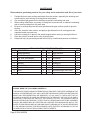
ITEM #42324 PIPE NOTCHER PARTS LIST
PART DESCRIPTION QTY PART DESCRIPTION QTY
1 Clamp Assembly 1 10 Angle Indicator 1
2 Handle/Clamp Screw 1 11 M8 Nut 2
3 5/8” Hole Saw Adapter 1 12 M8 Washer 9
4 5/8” Hole Saw Adapter Washer 1 13 Body 1
5 Bushing 2 14 Locking Pin 1
6 Spindle Support 1 15 M8 x 16 Bolt 3
7 Spindle 1 16 M8 x 20 Bolt 4
8 Rivet 4 17 Adjustable Angle Joint Plate 1
9 Label 1 18 Angle Indicator 1

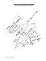
MODEL # 42324 PIPE NOTCHER PARTS DIAGRAM
Please refer to the parts list on previous page
Page 6 SKU # 42324

LIMITED 90 DAY WARRANTY
Harbor Freight Tools Co. makes every effort to assure that its products meet high quality
and durability standards, and warrants to the original purchaser that this product is free from
defects in materials and workmanship for the period of 90 days from the date of purchase. This
warranty does not apply to damage due directly or indirectly, to misuse, abuse, negligence or
accidents, repairs or alterations outside our facilities, criminal activity, improper installation,
normal wear and tear, or to lack of maintenance. We shall in no event be liable for death, in-
juries to persons or property, or for incidental, contingent, special or consequential damages
arising from the use of our product. Some states do not allow the exclusion or limitation of
incidental or consequential damages, so the above limitation of exclusion may not apply to
you. THIS WARRANTY IS EXPRESSLY IN LIEU OF ALL OTHER WARRANTIES, EXPRESS
OR IMPLIED, INCLUDING THE WARRANTIES OF MERCHANTABILITY AND FITNESS.
To take advantage of this warranty, the product or part must be returned to us with
transportation charges prepaid. Proof of purchase date and an explanation of the complaint
must accompany the merchandise. If our inspection veries the defect, we will either repair or
replace the product at our election or we may elect to refund the purchase price if we cannot
readily and quickly provide you with a replacement. We will return repaired products at our
expense, but if we determine there is no defect, or that the defect resulted from causes not
within the scope of our warranty, then you must bear the cost of returning the product.
This warranty gives you specic legal rights and you may also have other rights which
vary from state to state.
3491 Mission Oaks Blvd. • PO Box 6009 • Camarillo, CA 93011 • (800) 444-3353
Page 7 SKU # 42324
-
 1
1
-
 2
2
-
 3
3
-
 4
4
-
 5
5
-
 6
6
-
 7
7


Harbor Freight Tools Pipe/Tubing Notcher Owner's manual
- Category
- Power tools
- Type
- Owner's manual
- This manual is also suitable for
Ask a question and I''ll find the answer in the document
Finding information in a document is now easier with AI
Related papers
-
Harbor Freight Tools 46694 User manual
-
-
-
-
-
-
-
-
-
Chicago Electric 41453 User manual
Other documents
-
Grizzly T28929 Owner's manual
-
Power Fist 8536609 Owner's manual
-
-
Central Machinery Pipe/Tubing Notcher Owner's manual
-
-
Drill Master 95527 Assembly And Operation Instructions
-
 KAKA RA-1 Tube & Pipe Notcher User manual
-
Central Machinery 30027 Owner's manual
-
 Eastwood Professional Tubing Notcher Operating instructions
-

