Page is loading ...

DI-00X-00LVS-00C
INSTALLATION
PRECAUTIONS AND REQUIREMENTS:
All standard precautions for wiring traditional low voltage control devices apply:
1. The cable should not pass near any source of electrical noise or interference such as fluorescent circuits or motor wiring.
2. Close proximity to any AC wiring should be avoided.
3. All analog wiring shall be in it’s own conduit.
4. Any wire type capable of carrying the required voltage and current may be used.
5. Observe standard voltage drop calculations to ensure that no less than +10 volts are received by the station. Less than +10V and the LED’s will not be
bright enough to be seen or if voltage is quite low, may not light at all.
INTRODUCTION:
The Low Voltage Switches are a variant on the traditional low voltage switch. They provide a switched momentary
contact which closes a low voltage circuit when the switch is depressed and provides optional feedback to the user
through an LED contained within each button. Additionally, each station has a rear illuminated "locator" LED in the lower
left hand corner.
INSTALLATION REQUIREMENTS:
• MinimumBackBoxDimensions:
NEMA (US) markets: 1 gang device back box, 1-1/2" deep
For IEC (3x3) markets: 1 gang device back box, min 35mm deep, 47mm preferred.
Minimumverticalclearance69mm,minimumhorizontalclearance45mm.
Designedforhorizontalscrewmounting.
• Theswitchesarewiredusinganalogwiring,requiring1wireforeachswitchleg,1optionalwireforeachLED
indicator within each switch (if desired), 1 optional wire for the locator LED and 1 wire for the device for common or
+24V. As this is an analog system, any system topology is allowed. Additionally, the low voltage switch can provide
connections to common or +V upon a switch closure.
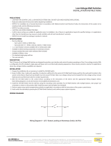
Typical connections to the device are as follows:
• The"S_"terminalsareconnectedtothe+24V/CMterminalwhentheswitchisdepressed.
• The LED inside each switch illuminates when the "L~' terminal for the switch is connected to either +10 - 24V or Common (the opposite of that connected
tothe+24V/CMterminal).
• The"LOC"atorLEDisilluminatedwhenitisconnectedtoeither+10-24VDCorCommon(theoppositeofthatconnectedtothe+24V/CMterminal).
CURRENT DRAW:
At 24 VDC, each LED on the station, both those in the buttons and the locator Led requires approximately 7.5mA. Therefore the total load of each station is as
shown in Current Draw chart below.
NOTE:Remembertoverifythatthesourceofthepowerforthelowvoltagestationsisadequateinsizeforthenumberofbuttonsandstationsyouhave
connected to it.
TERMINAL CONNECTION TYPES:
Depending on the needs of your equipment, the low voltage switch will support either closed circuit connection to common, or closed circuit +v. The Terminal
ConnectionTypeschartbelowliststheoptionsandrequirementsfortheL_,LOC,and+24V/CMterminals.
LOW VOLTAGE SWITCHES
Cat. Nos. LVS-01W, LVS-02W, LVS-03W, LVS-04W,
LVS-05W,LVS-06W,LVS-08W,LVS-10W,
LVS-S1W, LVS-S2W, LVS-S3W, LVS-S4W & LVS-S5W
Switch
LED LOCATOR
Switches
with LED
Indicator
CURRENT DRAW
Station
Unit Load Consumption @ 24Vdc
1 Unit Load = 25mA
Without Locator LED
Hooked Up
With Locator LED
Hooked Up
1Button 0.3 0.6
2Button 0.6 0.9
3Button 0.9 1.2
4Button 1.2 1.5
5Button 1.5 1.8
6Button 1.8 2.1
8Button 2.4 2.7
10Button 3.0 3.3
TERMINAL CONNECTION TYPES
Terminal
Cable Function
RECOMMENDED
WIRING METHOD
Expected
connection at the
"other end"
Z-MAX
Terminal*
OPTIONAL
WIRING METHOD
Expected
connection at the
"other end"
+24V/CM Input +24Vdc +24 Common
S1
Switch 1,
Switch
Output
+24Vdc, when
switch pressed
SWx lN
Common, when
switch pressed
L 1
Switch
1, LED
Input
Common, when
LED to be
illuminated
SWx
OUT
+24Vdc when LED
to be illuminated
LOC
Locator
LED
LED Lights when
connected to
Common
COM
LED Lights when
connected to
+24Vdc
NOTE: S1, L 1 terminals: Cross reference the "1" with the button number on
the label.
NOTE: *IfConnectingtoaZ-MAXrelaycabinet,connecttotheterminalas
indicated, using the recommended wiring method.

INSTALLATION FOR CAT. NOS. LVS-01W, -02W, -03W, -04W, -05W, -06W, -08W, -10W:
1.
If using a Decora Plus screwless wall plate, remove the center tabs from the device as shown in Figure A.
2.
Terminate the wiring to the appropriate terminals on your low voltage switch as is required for your application as shown in Figure B. See the Terminal
Connection Types table.
3.
When all wires have been terminated, gently stuff the wires back into the junction box in the wall.
4. S
ecurely mount the station to the wall using the provided screws as shown in Figure C.
5.
MountthewallplatetothestationasshowninFigure C.
INSTALLATION FOR CAT. NOS. LVS-S1W, -S2W, -S3W, -S4W, -S5W:
NOTE: A 35mm or preferred 47mm deep 2-tab junction box is required for these devices
.
1.
Terminate the wiring to the appropriate terminals on your low voltage switch as is
required for your application as shown in Figure B. See the Terminal Connection
Types table.
2.
When all wires have been terminated, gently stuff the wires back into the junction box
in the wall.
3. S
ecurely mount the station to the wall using the provided screws as shown in Figure D.
4.
MountthewallplatetothestationasshowninFigure D.
PROGRAMMING / OPERATION:
All System Programming, individual switch configuration, and other device configuration options is performed at the device to which your switch is connected.
Wiring and Installation
Figure A Figure B Figure C
Mounting
Screws
©2010LevitonMfg.Co.,Inc.
DI-00X-00LVS-00CFor Technical Assistance Call: 1-800-959-6004 or email: LMSTechSuppor[email protected] (U.S.A. Only)
LIMITED 2 YEAR WARRANTY AND EXCLUSIONS
Leviton warrants to the original consumer purchaser and not for the benefit of anyone else that this product at the time of its sale by Leviton is free of defects in materials and workmanship under normal
and proper use for two years from the purchase date. Leviton’s only obligation is to correct such defects by repair or replacement, at its option, if within such two year period the product is returned prepaid,
with proof of purchase date, and a description of the problem to Leviton Manufacturing Co., Inc., Att: Quality Assurance Department, 20497 S.W. Teton Ave, Tualatin OR 97062. This warranty excludes
and there is disclaimed liability for labor for removal of this product or reinstallation. This warranty is void if this product is installed improperly or in an improper environment, overloaded, misused, opened,
abused, or altered in any manner, or is not used under normal operating conditions or not in accordance with any labels or instructions. There are no other or implied warranties of any kind, including
merchantability and fitness for a particular purpose, but if any implied warranty is required by the applicable jurisdiction, the duration of any such implied warranty, including merchantability and fitness for
a particular purpose, is limited to two years. Leviton is not liable for incidental, indirect, special, or consequential damages, including without limitation, damage to, or loss of use of, any equipment,
lost sales or profits or delay or failure to perform this warranty obligation. The remedies provided herein are the exclusive remedies under this warranty, whether based on contract, tort or otherwise.
Figure D
Mounting
Screws
Installation for 3" x 3" junction box
/