I.S. 18 wiring grounding instructions
SAFETY WARNING: READ WIRING AND GROUNDING INSTRUCTIONS (I.S. 18)
AND ANY ADDITIONAL DIRECTIONS. TURN POWER SUPPLY OFF DURING
INSTALLATION. IF NEW WIRING IS REQUIRED, CONSULT A QUALIFIED
ELECTRICIAN OR LOCAL AUTHORITIES FOR CODE REQUIREMENTS.
wiring instructions
Indoor Fixtures
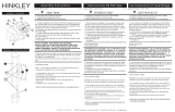
1. Connect positive supply wire (A) (typically black or the smooth, unmarked
side of the two-conductor cord) to positive fixture lead (B) with appropriately
sized twist on connector - see Drawings 1 or 2.
2. Connect negative supply wire (C) (typically white or the ribbed, marked
side of the two-conductor cord) to negative fixture lead (D).
3. Please refer to the grounding instructions below to complete all
electrical connections.
Outdoor Fixtures
1. Connect positive supply wire (A) (typically black or the smooth unmarked
side of the two-conductor cord) to positive fixture lead (B) with appropriately
sized twist on connector - see Drawings 2 or 3.
2. Connect negative supply wire (C) (typically white or the ribbed, marked
side of the two-conductor cord) to negative fixture lead (D).
3. Cover open end of connectors with silicone sealant to form a watertight seal.
• If installing a wall mount fixture, use caulk to seal gaps between the fixture
mounting plate (backplate) and the wall. This will help prevent water from
entering the outlet box. If the wall surface is lap siding, use caulk and a
fixture mounting platform specially.
4. Please refer to the grounding instructions below to complete all
electrical connections.
grounding instructions
Flush Mount Fixtures
For positive grounding in a 3-wire electrical system, fasten the fixture ground
wire (E) (typically copper or green plastic coated) to the fixture mounting strap (1)
with the ground screw (2) - see Drawing 1.
Note: On straps for screw supported fixtures, first install the two mounting screws in strap.
Any remaining tapped hole may be used for the ground screw.
Chain Hung Fixtures
Loop fixture ground wire (E) (typically copper or green plastic coated) under the
head of the ground screw (2) on fixture mounting strap (1) and connect to the
loose end of the fixture ground wire directly to the ground wire of the building
system with appropriately sized twist-on connectors - see Drawing 2.
Post-Mount Fixtures
Connect fixture ground wire (E) (typically copper or green plastic coated) to power
supply ground with appropriately sized twist-on connector inside post. Cover open
end of connector with silicone sealant to form a watertight seal - see Drawing 3.
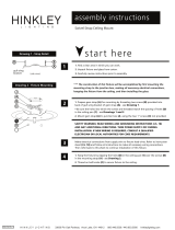
Drawing 1 - Flush Mount
Drawing 2 - Chain Hung
supply wire
fixture leads
twist-on
connectors
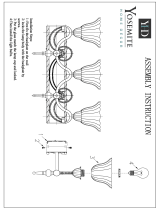
Drawing 3 - Post-Mount
twist-on
connectors
1
A CC
B
D
supply wire
fixture leads
A C
B
D
1
2
supply wire
fixture leads
A C
B
D
twist-on
connectors
E
2
E
E
E
E
E
E
I.S. 18
H I N K L E Y L I G H T I N G 33000 Pin Oak Parkway Avon Lake, OH 44012 800.446.5539 / 440.653.5500 hinkleylighting.com