Page is loading ...

Wattstopper
®
Low Voltage High/Low/Off PIR Fixture Integrated Outdoor Sensor
Basse Tension, Haut/Bas/Éteint
Luminaire avec détecteur IRP extérieur intégré
Bajo Voltaje, Alto/Bajo/Apagado
Sensor PIR para fixturas y uso exterior
Installation Instructions • Instructions d’Installation • Instrucciones de Instalación
No: 23937 – 12/17 rev. 3
Catalog Number • Numéro de Catalogue • Número de Catálogo: FSP-201
Country of Origin: Made in China • Pays d’origine: Fabriqué en Chine • País de origen: Hecho en China
FSP-201-U is BAA and TAA compliant (Product produced in the U.S.)
DESCRIPTION AND OPERATION
The FSP-201 is a motion sensor that dims lighting from high to low
based on movement. This slim, low-profile sensor is designed for
installation inside the bottom of a light fixture body. The PIR lens
module connects to the FSP-201 through a 1.30” diameter hole in
the bottom of the fixture.
The sensors use passive infrared (PIR) sensing technology that
reacts to changes in infrared energy (moving body heat) within
the coverage area. Once the sensor stops detecting movement
and the time delay elapses, lights will go from high to low mode
and eventually to an OFF position if it is desired. Sensors must
directly “see” motion of a person or moving object to detect them,
therefore careful consideration must be given to sensor luminaire
placement and lens selection. Avoid placing the sensor where
obstructions may block the sensor’s line of sight.
The FSP-201 operates at 12 - 32 VDC. It is designed to be
installed in indoor and outdoor environments.
SPECIFICATIONS
Voltage ...................................................................... 12 - 32 VDC
Current Consumption .......................................... 15 mA maximum
Wiring Terminals
Primary Voltage ........................................... +VDC, Com, Ctrl
Control Output ........................................... 100 mA maximum
Dimming Voltage ............Dim + (violet), Dim - (gray), Ground
Use Solid or Tinned Stranded Copper Conductor
...................................................................18AWG - 20AWG
Operating Temperature ...................-40°F (-40°C) to 176°F (80°C)
Tightening Nut Torque ................................................. 25-30 in-lbs
Dimensions
Collar ...............................................1.30” diameter (33.0mm)
Collar height ...................................................0.64” (16.3mm)
Body .........1.38” x 3.8” x 0.9” (35.1mm x 96.5mm x 22.9mm)
Weight ........................................................................2.4 oz (70 g)
Coverage
FSP-L2 Lens @ 8’ height ...........................up to 44’ diameter
FSP-L3 Lens @ 20’ height .........................up to 40’ diameter
FSP-L7 Lens @ 40’ height .......................up to 100’ diameter
Adjustments and Features
High Mode ............................................................... 0 V -10 V
Low Mode ................................................ . . . 0 V - 9.8 V, Off
Time Delay ..................................30 seconds, 1 min - 30 min
Cut Off ..............................Disable, 1 min - 59 min ,1 hr - 5 hr
Sensitivity ............................. On-Fix, Off-Fix, Low, Med, Max
Hold Off Setpoint .......................... Auto, Disable, 1 fc - 250 fc
Ramp Up ............................................Disable, 1 sec - 60 sec
Fade Down ......................................... Disable, 1 sec - 60 sec
Photocell Setpoint for On/Off ...................... Disable, 1-250 fc
Factory Defaults
High Mode ....................................................................... 10 V
Low Mode ................................................................. . . . 1 V
Time Delay .................................................................... 5 min
Cut Off .............................................................................. 1 hr
Sensitivity ....................................................................... Max
Hold Off Setpoint ....................................................... Disable
Ramp Up .................................................................... Disable
Fade Down ................................................................. Disable
Photocell Setpoint for On/Off ..................................... Disable
OPEN DEVICE for installation in a Listed Enclosure per Installation
Instructions.
www.legrand.us
800.879.8585
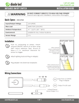
FSP-201
16088r1
CTRL
COM
+VDC
(violet)
(grey)
14-18 AWG Solid CU Wire Only
18-20 AWG Solid CU Wire Only
High/Low PIR Occupancy Sensor
12-32 VDC, 15mA
GRND
DIM-
DIM+
Appliance Control
88T9
IR Receiver
IR Transmitte
r
Light Sensor
Motion Indicator
Red LED
PIR Sensor
Sensor Protection Cap
NOTE: Remove Cap before use
Once powering the device up, the FSP-201 will use factory default
parameters to operate. If adjustments are needed, Wattstopper
FSIR-100 Wireless IR Configuration Tool must be used.

2
LENS OPTIONS
Several lenses are available for use with the FSP-201. Lenses give coverage at mounting heights between 8’ - 40’ for applications such
as offices, warehouses, and outdoor use. Density and range of the coverage is determined by the type of lens and mounting height.
Lens modules are IP-66 rated when combined with an FSP-201 sensor mounted to an IP-66 rated outdoor fixture. See the FSP-Lx
Coverage Guide for more information.
USING THE FSIR-100 CONFIGURATION TOOL
The configuration process establishes the appropriate parameters for the FSP-201 operation. This is done through the FSIR-100
Wireless IR Configuration Tool. If no configuration steps are taken, the sensor will use its default parameter values. Use of the FSIR-100
is highly recommended for ease of troubleshooting, and especially when the FSP-201 is mounted in a high location.
The FSIR-100 is a handheld tool for changing the defaults and testing the FSP-201.It provides wireless access to the FSP-201 sensors
for parameter changes and testing. The FSIR-100 display shows menus and prompts to lead you through each process. The navigation
pad provides a simple way to navigate through the customization fields.
Within a certain mounting height of the sensor, the FSIR-100 allows modification of the system without requiring ladders or tools, simply
with a touch of a few buttons.
WIRING
1. Determine an appropriate mounting location inside the light fixture
minimizing the electric light contribution to the sensor’s photocell.
Allow a minimum distance of 0.2” (5.1mm) from the wiring end of
the sensor to the wall of the fixture.
2. Drill a hole 1.30” (33.0mm) in diameter through the sheet metal in
the bottom of the fixture.
3. Add the rubber gasket to the threaded collar, and install the
sensor face down, parallel to the mounting surface. Ensure the
rubber gasket touches the inside surface of the fixture. Install
the plastic nut (or optional collar) securely against the fixture to a
torque of 25-30 in-lbs to ensure IP rating is maintained.
4. Align the locking features between the sensor and lens module
and push the lens module forward until the o-ring seals firmly.
Turn the lens module clockwise to ensure that it locks in place.
5. Connect wires as shown in the wiring diagram.
6. Restore power from the circuit breaker.
NOTE: An optional collar can be installed in place of the tightening nut.
See the Ordering Information table on page 4 for details.
Tightening Nut
(or Optional Collar)
Tightening Nut
(or Optional Collar)
Fixture
Wall
Lens Assembly
FSP-201
Outside
Fixture Wall
Inside Fixture
Wall
Rubber
Gasket
Rubber
Gasket
NOTE: The Outside Fixture Wall thickness should be no
greater than 0.125” (3.18mm) for optimal sensor
mounting and security.
NOTE: The FSP-201 must be grounded to ensure signal integrity, not for safety ground.
OUTDOORS—USE AT THE EXPOSED SENSOR COLLAR PART ONLY WHEN INSTALLED AT THE SPECIFIC LOCATION PER
INSTALLATION INSTRUCTIONS WITH A LISTED OUTDOOR ENCLOSURE.
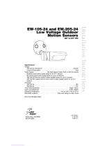
INSTALLATION
120 – 277 VAC (1
φ
), 50/60 Hz
20A Ballast/ELV/MLV/Tungsten/LED
16A E-Ballast/CFL
1HP @ 120/240VAC
20A 120VAC Plug Load – Receptacle
Class 2 Output
24 VDC, 225 mA
BZ-200 Power Pack
UL 2043 Plenum Rated
16094r1
Appliance
Control
LISTED
88T9
Control
Common
+24VDC
Red
White
Neut.
Power Pack
Red
Black
Blue
Switch
Lighting
Load
Black
Any 3-Wire
24VDC
Sensor
Hot
Red
Ground
Green
Class 2
wiring only
+VDC (Red)
COM (Black)
CTRL (Blue)
Non-Dimming
Ballast
Neutral
Line
Ground
www.legrand.us
800.879.8585
FSP-201
16088r1
CTRL
COM
+VDC
(violet)
(grey)
14-18 AWG Solid CU Wire Only
18-20 AWG Solid CU Wire Only
High/Low PIR Occupancy Sensor
12-32 VDC, 15mA
GRND
DIM-
DIM+
Appliance Control
88T9
www.legrand.us 800.879.8585
120 – 277 VAC (1
φ
), 50/60 Hz
20A Ballast/ELV/MLV/Tungsten/LED
16A E-Ballast/CFL
1HP @ 120/240VAC
20A 120VAC Plug Load – Receptacle
Class 2 Output
24 VDC, 225 mA
BZ-200 Power Pack
UL 2043 Plenum Rated
www.legrand.com • 800.879.8585
16094r1
Appliance
Control
LISTED
88T9
Control
Common
+24VDC
Red
White
Neut.
Power Pack
Red
Black
Blue
Switch
Lighting
Load
Black
Any 3-Wire
24VDC
Sensor
Hot
Red
Ground
Green
Class 2
wiring only
+VDC (Red)
COM (Black)
CTRL (Blue)
Dimming
Ballast/Driver
Neutral
Line
Ground
Ground (Green)
0-10V – (Gray)
0-10V + (Violet)
www.legrand.us
800.879.8585
FSP-201
CTRL
COM
+VDC
(violet)
(grey)
14-18 AWG Solid CU Wire Only
18-20 AWG Solid CU Wire Only
High/Low PIR Occupancy Sensor
12-32 VDC, 15mA
GRND
DIM-
DIM+
Appliance Control
88T9
WARNING: TURN THE POWER OFF AT THE
CIRCUIT BREAKER BEFORE WIRING.

3
NAVIGATION
Navigate from one field to another using (up) or (down) arrow keys. The active field is
indicated by flashing (alternates) between yellow text on black background and black
text on yellow background.
Once active, use the Select button to move to a menu or function within the active
field. Value fields are used to adjust parameter settings. They are shown in “less-than/
greater-than” symbols: <value>. Once active, change them using (left) and (right)
arrow keys. The right key increments and the left key decrements a value. Selections
wrap-around if you continue to press the key beyond maximum or minimum values.
Moving away from the value field overwrites the original value. The Home button
takes you to the main menu. The Back button can be thought of as an undo function.
It takes you back one screen. Changes that were in process prior to pressing the key
are lost.
TROUBLESHOOTING
Lights will not go to High Mode:
• Check all wire connections and verify the dimming wires are tightly secured.
• Make sure that the sensor is not obstructed.
• Check light level parameter, to find out the amount of light that the sensor is detecting. Cover the sensor lens to simulate darkness
in the room. If the lights come ON, the setpoint needs to be adjusted. If set for minimum, more than 1 fc at the sensor of ambient
light will cause the lights to be held OFF. See the new settings section for instructions.
• If lights still do not turn ON, call 800.879.8585 for technical support.
15'-32'
* Distance may vary depending on
the lighting environment
IR COMMUNICATION
IR communication can be affected by the mounting height of the sensor and high
ambient lighting such as direct daylight or electric light such as floodlights, fluorescent
lamps, LED’s and some halogen.
When trying to communicate with the FSP-201, be sure to be positioned under the
sensor without any obstructions. Every time the commissionng tool establishes
communication with the FSP-201, the controlled load will cycle.
FSP-2X1
HBP-111
Home/Main
Menu
Up
Select
Down
Right/Next
Left
Back
Power
On/Off
BAT=
IR tx/rx
BATTERIES
The FSIR-100 operates on three
standard 1.5V AAA Alkaline batteries or
three rechargeable AAA NiMH batteries.
The battery status displays in the upper
right corner of the display. Three bars
next to BAT= indicates a full battery
charge. A warning appears on the
display when the battery level falls
below a minimum acceptable level. To
conserve battery power, the FSIR-100
automatically shuts off 10 minutes after
the last key press.
If communication is not successful, move closer to the sensor (if
possible).
If still not successful, there may be too much IR interference from
other sources. Programming the unit at night when there is no daylight
available may be the only way to communicate with the sensor.
+VDC Output (Red)
COM/GND (Black)
Neutral LineGround
Ground (Green)
0-10V – (Gray)
0-10V + (Violet)
www.legrand.us
800.879.8585
FSP-201
CTRL
COM
+VDC
(violet)
(grey)
14-18 AWG Solid CU Wire Only
18-20 AWG Solid CU Wire Only
High/Low PIR Occupancy Sensor
12-32 VDC, 15mA
GRND
DIM-
DIM+
Appliance Control
88T9
Dim-to-Off
Ballast/Driver
Wiring with an
external DC
power supply

4
Lights will not go into Low Mode:
• The time delay can be set from a minimum of 30 seconds to a maximum of 30 minutes. Ensure that the time delay is set to the
desired delay and that there is no movement within the sensor’s view for that time period.
• To quickly test the unit operation, enable test mode and move out of the sensor’s view. Lights should fade to low mode after
5 seconds.
• If lights still do not fade to Low Mode, call 800.879.8585 for technical support.
Lights will not turn OFF:
• Cut Off time may be set to “Disable.”
• Ensure that the Cut Off is set to the desired time and that there is no movement within the sensor’s view for that time period when
the lights are in Low Mode.
• To quickly test the unit’s operation, enable test mode and move out of the sensor’s view. Lights should fade to low mode after 5
seconds and then turn OFF (if cut off is enabled) after 10 sec.
• If lights still do not turn OFF, call 800.879.8585 for technical support
False Triggering may occur if the sensor is exposed to high ambient temperature conditions and the unit is set to maximum
sensitivity for PIR detection.
• If this occurs, reduce the PIR sensitivity setting from maximum to a medium point and re-check unit operation.
• If experiencing false triggering during fade down/Off, try increasing the fade time.
Lights do not turn ON:
Check for blinking red LED. If the LED blinks with long pulses, as opposed to short pulses, the sensor has reached its Hold Off setpoint
or Photocell Light Level setpoint.
Lights suddenly turn off and will not come back on:
Check for blinking red LED. If the LED blinks with long pulses, as opposed to short pulses, the sensor has reached its Hold Off setpoint
or Photocell Light Level setpoint.
There is no IR communication:
Perform a power cycle on the FSP-201.
OPERATION DURING POWER-UP
During the sensor warm-up period, which can last up to 5 seconds after initial power-up (or after a lengthy power outage), the load will
remain ON until the selected time delay expires.
ORDERING INFORMATION
Catalog # Description
FSP-201 Digital High/Low PIR Fixture Integrated Sensor
FSIR-100 Configuration Tool
FSP-L2 60° lens, up to 44’ diameter at 8’ height
FSP-L3 360° lens, up to 40’ diameter at 20’ height
FSP-L7 360° lens, up to 100’ diameter at 40’ height
FSP-C1 Small collar, for use with FSP-L2 and FSP-L3 lenses
FSP-C2 Large collar, for use with FSP-L7 lens
BZ-50 Power Pack: 120/277VAC, 50/60Hz, 20A ballast or incandescent
BZ-150 Power Pack: 120/277VAC, 50/60Hz, 20A ballast or incandescent, with Hold-On and Hold-Off capability
BZ-200 Power Pack: 120/277VAC, 50/60 Hz, 20A Ballast/ELV/MLV/Incandescent/LED, 16A, E-Ballast/CFL/Plug Load
BZ-250 Power Pack: 120/277VAC, 50/60 Hz, 20A, Ballast/ELV/MLV/Incandescent/LED, 16A E-Ballast/CFL/Plug Load,
with Hold-On/Hold-Off capability
BZ-250-347 Power Pack: 120/347VAC, 50/60 Hz, 16A Ballast/ELV/MLV/Incandescent/LED/ E-Ballast/CFL, 15A Plug Load,
with Hold-On/Hold-Off capability
Sensor is White.
/