BEA SPARROW User guide

Type
User guide

BEA SPARROW is a motion activation sensor for automatic industrial doors. It uses microwave technology to detect movement with adjustable detection speed and field size. It can be mounted at various heights and angles, making it suitable for different applications. The sensor has immunity filter settings to reduce false triggers and can be configured for one-way or two-way detection. It also features an access code for added security.

BEA SPARROW is a motion activation sensor for automatic industrial doors. It uses microwave technology to detect movement with adjustable detection speed and field size. It can be mounted at various heights and angles, making it suitable for different applications. The sensor has immunity filter settings to reduce false triggers and can be configured for one-way or two-way detection. It also features an access code for added security.

75.5730.04 SPARROW 20190916 Page 1 of 4
2
1
3
4
5
6
SPARROW
75.5730.04 SPARROW 20190916 Page 1 of 4
Motion activation sensor for
automatic, industrial doors
ENGLISH
Visit website for
available languages of
this document.
1. cover
2. main connector
3. radar antenna
4. DIP-switch
5. push buttons
6. LED
DESCRIPTION
TECHNICAL SPECIFICATIONS
Technology: microwave
Transmitted frequency: 24.150 GHz
Transmitted radiated power: <20 dBm EIRP
Transmitted power density: < 5 mW/cm
2
Detection mode: motion
Min. detection speed: 2 in/s (measured in the sensor axis)
Supply voltage: 12 – 24 V AC ±10%
12 – 24 V DC +30% / -10%
Mains frequency: 50 – 60 Hz
Max. power consumption: <2 W
Output:
max. contact voltage:
max. contact current:
max. switching power:
relay (free of potential changeover contact)
42V AC – 60 V DC
1A (resistive)
30W (DC) / 60VA (AC)
Mounting height: 6’6” – 20’ (78” – 240”)
Degree of protection: IP64
Temperature range: -22 – 140 °F
Dimensions: 5’5” × 2” × 2 1/4” ( L × H × W)
Tilt angles: 0 – 90° vertical
-120 – 120° lateral
Material: ABS
Weight: 5.8 oz
Cable length: 30’
Norm conformity: R&TTE 1999/5/EC
EMC 2004/108/EC
Specifications are subject to change without prior notice.
All values measured in specific conditions.
Page 2 of 4 75.5730.04 SPARROW 20190916
1
2
1
180°
2
3 4
5
Page 2 of 4 75.5730.04 SPARROW 20190916
MOUNTING & WIRING
The sensor can be installed
in various positions.
Always verify the antenna
position.
The sensor can easily replace other sensors by
using the retrofit clip.
1. Remove the clip.
2. Mount it with the existing screw.
3. Slide the sensor onto the clip.
Before mounting: After mounting:
TIPS
Avoid proximity to neon
lamps or moving objects.
Do not cover the sensor.
Drill 2 holes using
the mounting template.
Mount the sensor securely to
avoid vibrations.
Drill a hole for the cable and pull
tinned end through towards the
sensor...
Connect the wires accordingly.
12–24 AC/DC – brown, green
COM – white
NO/NC – yellow
Pass the cable through the
opening.
... or use one of the cable conduits.
Avoid using the top conduit to ensure
weatherproofing.
OPENING & CLOSING
75.5730.04 SPARROW 20190916 Page 3 of 4
3
4
0
1
2
1
2
0
1
2
3
3
3
0
1
2
1
2
0
1
2
3
3
3
1
13 ft 20 ft
2 3
< < > >
75.5730.04 SPARROW 20190916 Page 3 of 4
DETECTION FIELD
Adjust the lateral antenna angle.
Adjust the vertical antenna angle.
If mounting height is above 14’ 6"
(174"), activate BOOST function by
DIP switch.
Mounting height: 13 ft
Boost function: OFF
Factory values
Mounting height: 20 ft
Boost function: ON
Factory values
NOTES:
1. 1 × 1 grid is approximately 3.28 ft × 3.28 ft.
SETTINGS (by remote control or push buttons)
XXS
FIELD SIZE
IMMUNITY
FILTER
DETECTION
MODE
OUTPUT
CONFIG
Factory
Values
REMOTE CONTROL
XS
normal
A
S
high
uni
P
uni
AWAY
L XL XXL
bi = two-way detection
uni = one-way detection towards sensor
uni AWAY = one-way detection away from sensor
A = active output (NO-contact)
P = passive output (NC-contact)
bi
blue
FIELD SIZE
OR
RESETTING TO FACTORY VALUES:
PUSH BUTTON
Page 4 of 4 75.5730.04 SPARROW 20190916Page 4 of 4 75.5730.04 SPARROW 20190916
Door will not open.
LED is OFF.
Sensor power is OFF. Check wiring and power supply.
Door will not close.
LED is OFF.
Improper output
configuration on sensor.
Check output configuration setting
on each sensor connected to the door
operator.
Verify door control is operational.
Improper wiring at sensor.
Verify wiring at sensor.
Door opens and
closes constantly.
Blue LED is ON.
Sensor is disturbed by
door motion or vibrations
caused by door motion.
Ensure sensor is mounted properly.
Ensure detection mode is unidirectional.
Increase tilt angle.
Reduce field size.
Increase immmunity filter.
Sensor detects
objects outside its
detection field.
Blue LED is ON.
Metallic environment. Increase immunity filter.
Decrease field size.
Incorrect tilt angle.
Change sensor tilt angle.
Sensor detects for
no apparent reason
when raining.
Blue LED is ON.
Sensor detects motion of
rain drops.
Ensure detection mode is unidirectional.
Increase immmunity filter.
Install the ERC (rain accessory).
Blue LED flashes
quickly after
unlocking.
Sensor needs an access
code to unlock.
Enter an access code.
Cycle power supply to access the
sensor. Change/Delete access code.
Sensor does not
respond to remote
control.
Batteries in remote control
are weak or improperly
installed.
Check and change the batteries, if
necessary.
Remote control is oriented
incorrectly.
Point the remote control towards the
sensor.
BEA, Inc., the sensor manufacturer, cannot be held responsible for incorrect installations or inappropriate adjustments of the sensor/device; therefore,
BEA, Inc. does not guarantee any use of the sensor outside of its intended purpose.
BEA, Inc. strongly recommends that installation and service technicians be AAADM-certifi ed for pedestrian doors, IDA-certifi ed for doors/gates, and
factory-trained for the type of door/gate system.
Installers and service personnel are responsible for executing a risk assessment following each installation/service performed, ensuring that the sensor
system installation is compliant with local, national, and international regulations, codes, and standards.
Once installation or service work is complete, a safety inspection of the door/gate shall be performed per the door/gate manufacturer recommendations
and/or per AAADM/ANSI/DASMA guidelines (where applicable) for best industry practices. Safety inspections must be performed during each service
call – examples of these safety inspections can be found on an AAADM safety information label (e.g. ANSI/DASMA 102, ANSI/DASMA 107).
Verify that all appropriate industry signage and warning labels are in place.
BEA, INC. INSTALLATION/SERVICE COMPLIANCE EXPECTATIONS
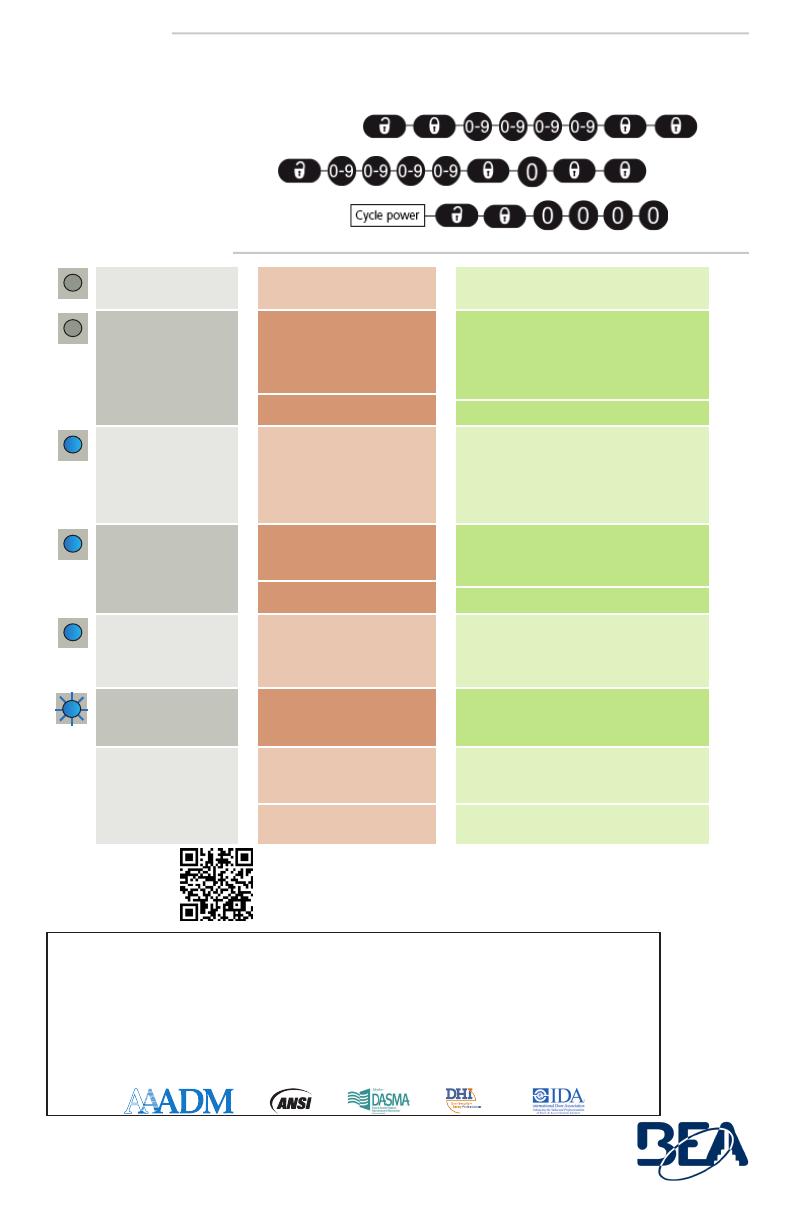
The access code (1 to 4 digits) is recommended to program sensors installed close to each other.
If you forget the access code, cycle the power supply.
Within the first minute, you can access the sensor without introducing any access code.
SAVING OR CHANGING AN ACCESS CODE:
DELETING AN ACCESS CODE:
DELETING AN UNKNOWN ACCESS CODE:
ACCESS CODE
TROUBLESHOOTING
Tech Support & Customer Service: 1-800-523-2462
General Tech Questions: [email protected] | Tech Docs: www.BEAsensors.com
©BEA | Original Instructions | PLEASE KEEP FOR FURTHER USE - DESIGNED FOR COLOR PRINTING
Can’t find your answer?
Visit www.beainc.com or scan QR code for Frequently Asked Questions!
  • Page 1 1
  • Page 2 2
  • Page 3 3
  • Page 4 4

BEA SPARROW User guide

Type
User guide

BEA SPARROW is a motion activation sensor for automatic industrial doors. It uses microwave technology to detect movement with adjustable detection speed and field size. It can be mounted at various heights and angles, making it suitable for different applications. The sensor has immunity filter settings to reduce false triggers and can be configured for one-way or two-way detection. It also features an access code for added security.

Ask a question and I''ll find the answer in the document

Finding information in a document is now easier with AI