Roland JUNO-DS61 User guide

Category
Musical Equipment
Type
User guide

This manual is also suitable for

Parameter Guide
© 2015 ROLAND CORPORATION
Contents
Additional Explanation
................................ 2
Panel Descriptions
.................................... 2
Patch Mode
.......................................... 2
Performance Mode
. . . . . . . . . . . . . . . . . . . . . . . . . . . . . . . . . . . . 2
Key Touch
........................................... 2
Sample Import
....................................... 2
Editing a Patch/Drum Kit
................................ 2
Editing a Performance
.................................. 2
Pattern Sequencer
..................................... 3
Realtime Erase
..................................... 3
Saving a Pattern As a “Performance” (SAVE AS PERFORM)
. . . . . . . 3
Turning the Display Backlight On/O
...................... 3
Demo Songs
......................................... 3
Patch Mode
........................................... 4
Patch/Drum Kit Edit
.................................... 4
Procedure
......................................... 4
About the Parameters
................................ 4
Patch Parameters
................................... 4
Drum Kit Parameters
................................. 14
Eects Edit
.......................................... 17
Signal Flow
........................................ 17
Procedure
......................................... 17
Eects Parameters
................................... 18
Performance Mode
.................................... 19
Performance Edit
..................................... 19
Procedure
......................................... 19
Performance Parameters
.............................. 19
Part Edit
............................................. 21
Procedure
......................................... 21
Performance Parameters
.............................. 21
Eects Edit
.......................................... 23
Signal Flow
........................................ 23
Procedure
......................................... 23
Eects Parameters
................................... 24
Sample Edit
........................................... 25
Procedure
........................................... 25
Sample Parameters
.................................... 25
Editing Arpeggios
..................................... 29
Selecting Ascending/Descending Variations (Motif)
........... 29
Editing the Vocoder/Auto Pitch
........................ 30
Saving the Vocoder/Auto Pitch Settings (Write)
.............. 30
Creating an Original Scale (USER SCALE)
............... 31
Setting a User Scale
.................................... 31
Recalling a User Scale
.................................. 31
System Settings
....................................... 32
Procedure
........................................... 32
System Parameters
.................................... 32
Connecting to a Computer via USB
..................... 35
Installing the USB Driver
. . . . . . . . . . . . . . . . . . . . . . . . . . . . . . . . 35
Making USB Driver Settings
............................. 35
Using the JUNO-DS with DAW Software
................ 36
Using the JUNO-DS As a DAW Controller
................... 36
Using the JUNO-DS to Control DAW Software
............... 36
Assigning Functions to Knobs and Sliders
.................. 37
Using the JUNO-DS As a MIDI Keyboard
.................... 37
Playing the JUNO-DS’s Sound Generator from DAW Software
... 37
Using the JUNO-DS As an Audio Interface
.................. 38
Saving the DAW CONTROL Settings
....................... 38
Error Messages
........................................ 39
MFX/Chorus/Reverb Parameters
....................... 40
MFX Parameters (MFX, MFX1–3)
.......................... 40
Chorus Parameters
.................................... 58
Reverb Parameters
.................................... 58
Waveform List
......................................... 59
Patch List
............................................. 66
Performance List
...................................... 76
Drum Kit List
.......................................... 76
Drum Kit Assign List
................................... 77
Rhythm Pattern List
................................... 85
Pattern List
............................................ 86
Arpeggio Style List
.................................... 86
Vocoder/Auto Pitch List
................................ 86
Placing This Unit on a Stand
........................... 87
01
2
Additional Explanation
Panel Descriptions
[NUMERIC] button
When this button is on (lit), you can use the [0]–[9] buttons to enter
numeric values.
* You can use this button only in the PATCH screen and PERFORM
screen.
[ENTER] button
Used to execute an operation.
List display
You can move the cursor to a parameter and press the [ENTER] button
to see a list of that parameter’s values.
You can select a value from the list that’s shown.
(Example)
In the PATCH screen, move the cursor to the patch number and press
the [ENTER] button to see the patch list.
Press the [EXIT] button to return to the previous screen.
Patch Mode
5
If you press the same category button in succession, the patch changes as follows
each time you press the button.
Each time you press the button, the rst patch of the two sub-
categories is selected.
If a user patch is saved
Each time you press the button, the rst patch of sub-category
1
0
sub-category 2
0
user
0
sub-category 1 … is selected.
If a user patch is saved
Each time you press the button, the rst patch of
preset
0
user
0
preset … is selected.
Performance Mode
5
You can use pads [1]–[8] to select the applicable part (current part).
5
Pressing a pad [1]–[8] selects part 1–8.
5
Hold down the [SHIFT] button and press pad [1]–[8] to select part 9–16.
16-part mode
5
Within Performance mode, the state in which neither split, dual, nor super layer is
selected is called “16-part mode.
1
2
3
4
5
6
7
8
10
9
No. Explanation
1
Eect on (lit)/o (unlit)
2
Tempo
3
Performance bank
4
Performance number/name
5
Current part
No. Explanation
6
Category number/Patch name
7
Level of the current part
8
Level meter
9
Octave Shift setting
10
Parameters that can currently be
adjusted by the control knobs
When you play the keyboard, you’ll hear the current part and the parts whose
keyboard switch (p. 19, p. 20, p. 22) is on.
Adjusting the volume
You can use the [UPPER] LEVEL slider and [LOWER] LEVEL slider to adjust the part 1
and part 2 volume (LEVEL).
Key Touch
5
Depending on the KEY TOUCH setting, the [KEY TOUCH] button is lit or unlit.
Lit When the Velocity setting is “REAL
Unlit When the Velocity setting is “1–127”
Sample Import
5
When importing a sample, the OPTIMIZE window might appear depending on the
user memory usage status.
OK Memory is optimized, and then the sample import is executed.
CANCEL Sample import is cancelled.
Editing a Patch/Drum Kit
PATCH EDIT
5
In the PATCH EDIT screen when editing each tone, you can use pads [1]–[8] to
perform the following operations.
Pads [5]–[8]
Turn each tone on (pad lit) or o.
When a tone is on, a
(
symbol appears.
Pads [1]–[4]
Make the pad(s) light to specify the tone(s) that you want to edit.
You can also make multiple pads light to select multiple tones.
5
In the PATCH EDIT screen, press the [MENU] button to open the INIT MENU window.
Select “PATCH” or “TONE” and then press the [ENTER] button to initialize the selected
patch or tone.
DRUM KIT EDIT
5
A drum kit consists of a percussion instrument sound (tone) assigned to each key.
The tone that’s assigned to each key consists of a combination of up to four waves.
Drum Kit Edit lets you edit the settings of the tone that’s assigned to each key.
5
In the DRUM KIT EDIT screen, when editing the four waves that make up the tone
assigned to the selected key, you can use pads [1]–[8] to perform the following
operations.
Pads [5]–[8]
Turn each wave on (pad lit) or o.
When a wave is on, a
(
symbol appears.
Pads [1]–[4]
Make the pad(s) light to specify the wave(s) that you want to edit.
You can also make multiple pads light to select multiple waves.
5
In the DRUM KIT EDIT screen, press the [MENU] button to open the INIT MENU
window. Select “DRUM” or TONE” and then press the [ENTER] button to initialize the
selected drum kit or the tone of the selected key.
Editing a Performance
5
“PERFORMMANCE EDIT” lets you edit while viewing a list of the settings of all parts,
and “PART EDIT” lets you edit each part of the performance individually.
* PERFORMANCE EDIT and PART EDIT have the same parameters in common.
5
In the PERFORM EDIT or PART EDIT screen, you can use pads [1]–[8] to select the
part that you want to edit. If you hold down the [SHIFT] button and press a pad [1]–
[8], a part 9–16 is selected.
5
In the PERFORM EDIT screen, press the [MENU] button to open the INIT MENU
window. Select “PERFORM” or “PART” and press the [ENTER] button to initialize the
selected performance or part.
3
Additional Explanation
Pattern Sequencer
5
In the PATTERN SEQUENCER screen, you can long-press the [LOOP] button to open
the LOOP window, where you can make loop-related settings. Press the [EXIT]
button to close the LOOP window.
Parameter Explanation
Loop Switch
Species whether playback will loop (ON) or not loop (OFF).
* You can also switch this by pressing the [LOOP] button.
OFF, ON
Loop Rec
Species whether to loop-record (ON) or not loop-record (OFF).
* You can also switch this by pressing the [LOOP] button while holding
down the [SHIFT] button.
OFF, ON
5
Use the [UPPER] slider to adjust the level of track 1, and the [LOWER] slider to adjust
the level of track 2.
5
Use the [PHRASE PAD] slider to increase or decrease the level that’s specied for
tracks 3–8 while maintaining the balance between these tracks.
5
Press the [MIXER] button to open the MIXER screen. Here you can set the pan and
level of each track.
You can use pads [1]–[8] to select a track to edit.
Use the [UPPER]/[LOWER]/[PHRASE PAD] sliders to adjust the level.
MEMO
Tracks 1–7 are assigned to parts 1–7, and track 8 is assigned to part 10.
Realtime Erase
Erasing only specied notes during recording or playback
(REALTIME NOTE ERASE)
1.
During recording or playback, hold down the [RHYTHM PATTERN] button
and press the [ERASE] button.
The REALTIME NOTE ERASE window appears.
2.
Press a key on the keyboard to specify the note that you want to erase.
3.
Press the [ERASE] button.
While you continue holding down the key, only the note you specify is erased from
the selected track.
Erasing only movements of knobs or the bender/modulation lever
during recording or playback
1.
During recording or playback, hold down the [MUTE] button and press the
[ERASE] button.
Only while you continue holding down these buttons, movements of the knobs and
the bender/modulation lever are erased from the selected track.
Saving a Pattern As a “Performance” (SAVE AS PERFORM)
Settings related to the sound of the pattern (preset/user) used in the pattern
sequencer can be saved as a performance.
For example, if you want to export a pattern to SMF, use your DAW to edit it into a
complete song, and then use the JUNO-DS to play this song data, the performance
saved by the “SAVE AS PERFORM” function can be recalled to play the data using the
original sound.
1.
In the PATTERN SEQUENCER screen, select a pattern.
2.
Press the [MENU] button.
The MENU screen appears.
3.
Move the cursor to “PATTERN UTILITY, and press the [ENTER] button.
4.
Move the cursor to “SAVE AS PERFORM, and press the [ENTER] button.
The SAVE AS PERFORM screen appears.
5.
Use the value dial to select the write destination performance, and press
the [ENTER] button.
A conrmation message appears.
If you decide to cancel, press the [EXIT] button.
6.
Move the cursor to “OK, and press the [ENTER] button.
Writing is complete when the screen indicates “Completed!”
NOTE
Never turn o the power while the screen indicates Writing....
Turning the Display Backlight On/O
To reduce battery consumption, you can turn o the display backlight when its not
required.
1.
Hold down the [SHIFT] button and press the [EXIT] button.
The display backlight will turn o.
Turning the display backlight on
1.
Hold down the [SHIFT] button and press the [ENTER] button.
The display backlight will turn on.
Demo Songs
1 Wonder
Copyright © 2015 Roland Corporation
2 There There There
4
Patch Mode
Patch/Drum Kit Edit
Procedure
1.
Select a patch or drum kit that you want to edit.
2.
Press the [SAMPLE IMPORT] button and [DAW CONTROL] button
simultaneously.
The EDIT MENU screen appears.
3.
Move the cursor to “PATCH EDIT” or “DRUM KIT EDIT, and press the [ENTER]
button.
The PATCH EDIT or DRUM KIT EDIT screen appears.
MEMO
5
In the PATCH EDIT screen when editing each tone, you can use pads [1]–[8] to
perform the following operations.
Pads [5]–[8]
Turn each tone on (pad lit) or o.
When a tone is on, a
(
symbol appears.
Pads [1]–[4]
Make the pad(s) light to specify the tone(s) that you want to edit.
You can also make multiple pads light to select multiple tones.
5
In the PATCH EDIT screen, press the [MENU] button to open the INIT MENU
window. Select “PATCH” or “TONE” and then press the [ENTER] button to
initialize the selected patch or tone.
MEMO
5
In the DRUM KIT EDIT screen, when editing the four waves that make up the
tone assigned to the selected key, you can use pads [1]–[8] to perform the
following operations.
Pads [5]–[8]
Turn each wave on (pad lit) or o.
When a wave is on, a
(
symbol appears.
Pads [1]–[4]
Make the pad(s) light to specify the wave(s) that you want to edit.
You can also make multiple pads light to select multiple waves.
5
In the DRUM KIT EDIT screen, press the [MENU] button to open the INIT MENU
window. Select “DRUM” or TONE” and then press the [ENTER] button to
initialize the selected drum kit or the tone of the selected key.
4.
Move the cursor to tab, and use the [
K
] [
J
] buttons to switch the pages.
5.
Move the cursor to the parameter that you want to edit, and use the value
dial to change the value.
6.
To save the edited settings, perform the operation “Saving Your Settings
(Write)” (refer to owner’s manual).
About the Parameters
5
Parameters marked with a
2
can be controlled using Matrix control (p. 12).
5
Some parameters (such as Rate or Delay Time) can be set in terms of a note value.
Sixty-fourth-
note triplet
Sixty-fourth
note
Thirty-second-
note triplet
Thirty-second
note
Sixteenth-note
triplet
Dotted thirty-
second note
Sixteenth note
Eighth-note
triplet
Dotted
sixteenth note
Eighth note
Quarter-note
triplet
Dotted eighth
note
Quarter note Half-note triplet
Dotted quarter
note
Half note
Whole-note
triplet
Dotted half note Whole note
Double-note
triplet
Dotted whole
note
Double note
NOTE
If you specify the delay time as a note value, slowing down the tempo will not
change the delay time beyond a certain length.
This is because there is an upper limit for the delay time; if the delay time is
specied as a note value and you slow down the tempo until this upper limit
is reached, the delay time cannot change any further. This upper limit is the
maximum value that can be specied when setting the delay time as a numerical
value.
Patch Parameters
COMMON
Parameter Value/Explanation
Patch Category
Species the type (category) of the patch.
* If you select “NO ASSIGN” as the category, it won’t be possible to select
the patch on the JUNO-DS itself.
Refer to “Category List” (p. 5).
Patch Level
Species the volume of the patch.
0–127
Patch Pan
Species the pan of the patch.
“L64” is far left, “0” is center, and “63R is far right.
L64–0–63R
Patch Priority
This determines how notes will be managed when the maximum
polyphony is exceeded (128 voices).
LAST
The last-played voices will be given priority, and currently
sounding notes will be turned o in order, beginning with
the rst-played note.
LOUDEST
The voices with the loudest volume will be given priority,
and currently sounding notes will be turned o, beginning
with the lowest-volume voice.
Octave Shift
Adjusts the pitch of the patchs sound up or down in units of an octave (±3
octaves).
-3–3
Patch Coarse Tune
Adjusts the pitch of the patchs sound up or down in semitone steps (±4
octaves).
-48–48
Patch Fine Tune
Adjusts the pitch of the patchs sound up or down in 1-cent steps (±50
cents).
-50–50
Stretch Tune
Depth
Stretched tuning (a system by which acoustic pianos are normally tuned,
causing the lower range to be lower and the higher range to be higher
than the mathematical tuning ratios would otherwise dictate)
OFF Equal temperament
1–3
Higher settings will produce the greater dierence in the
pitch of the low and high ranges.
Pitch dierence from
equal temperament
Parameter value
Low note range High note range
Analog Feel
Species the depth of 1/f modulation that is to be applied to the patch.
By adding this “1/f modulation, you can simulate the natural instability
characteristic of an analog synthesizer.
0–127
Cuto Oset
Cuto Frequency Oset alters the cuto frequency of the overall patch,
while preserving the relative dierences between the cuto frequency
values set for each tone in the Cuto Frequency (p. 8).
* This value is added to the cuto frequency value of a tone, so if the
cuto frequency value of any tone is already set to “127” (maximum),
positive “+” settings here will not produce any change.
-63–+63
Resonance Oset
Resonance Oset alters the resonance of the overall patch, while
preserving the relative dierences between the resonance values set for
each tone in the Resonance (p. 8).
* This value is added to the resonance value of a tone, so if the resonance
value of any tone is already set to “127” (maximum), positive “+” settings
here will not produce any change.
-63–+63
Attack Time Oset
Attack Time Oset alters the attack time of the overall patch, while
preserving the relative dierences between the attack time values set for
each tone in the TVA-Env Time 1 (p. 10), TVF-Env Time 1 (p. 9).
* This value is added to the attack time value of a tone, so if the attack
time value of any tone is already set to “127” (maximum), positive “+”
settings here will not produce any change.
-63–+63
Release Time
Oset
Release Time Oset alters the release time of the overall patch, while
preserving the relative dierences between the release time values set for
each tone in the TVA-Env Time 4 (p. 10), TVF-Env Time 4 (p. 9).
* This value is added to the release time value of a tone, so if the release
time value of any tone is already set to “127” (maximum), positive “+”
settings here will not produce any change.
-63–+63
5
Patch Mode
Parameter Value/Explanation
Velocity Sens
Oset
Velocity Sens Oset alters the Velocity Sensitivity of the overall patch while
preserving the relative dierences between the Velocity Sensitivity values
set for each tone in the parameters below.
Cuto V-Sens (p. 9)
Level V-Sens (p. 10)
* This value is added to the velocity sensitivity value of a tone, so if the
velocity sensitivity value of any tone is already set to “+63” (maximum),
positive “+” settings here will not produce any change.
-63–+63
Mono/Poly
Species whether the patch will play polyphonically (POLY) or
monophonically (MONO).
The “MONO” setting is eective when playing a solo instrument patch such
as sax or ute.
MONO Only the last-played note will sound.
POLY Two or more notes can be played simultaneously.
Legato Switch
Species whether the Legato Switch will be used (ON) or not (OFF).
With the Legato Switch parameter “ON, pressing a key while continuing
to press a previous key causes the note to change pitch to the pitch of the
most recently pressed key, sounding all the while. This creates a smooth
transition between notes, which is eective when you wish to simulate the
hammering-on and pulling-o techniques used by a guitarist.
* Legato Switch is valid when the Mono/Poly is set to “MONO.
OFF, ON
Legato Retrigger
The setting determines whether sounds are replayed (ON) or not (OFF)
when performing legato. Normally you will leave this parameter “ON.
When “OFF, when one key is held down and another key is then pressed,
only the pitch changes, without the attack of the latter key being played.
Set this to “OFF” when performing wind and string phrases or when using
modulation with the mono synth keyboard sound.
* Legato Retrigger is valid when the Mono/Poly is set to “MONO” and the
Legato Switch is set to “ON.
OFF, ON
MEMO
Let’s say you have the Legato Switch set to “ON, and the Legato Retrigger set to “OFF. When
you try to sound a legato (by pressing a higher key while a lower key is held down), the pitch
may sometimes not be able to rise all the way to the intended pitch (stopping instead at an
intermediate pitch). This can occur because the limit of pitch rise, as determined at the wave
level, has been exceeded. Additionally, if diering upper pitch limits are used for the waves of
a Patch that uses multiple tones, it may stop being heard in MONO. When making large pitch
changes, set the Legato Retrigger to “ON.
Portamento
Switch
Species whether the portamento eect will be applied (ON) or not (OFF).
OFF, ON
Portamento Mode
Species the performance conditions for which portamento will be
applied.
NORMAL Portamento will always be applied.
LEGATO
Portamento will be applied only when you play legato (i.e.,
when you press the next key before releasing the previous
key).
Portamento Type
Species the type of portamento eect.
RATE
The time it takes will depend on the distance between the
two pitches.
TIME
The time it takes will be constant, regardless of how far
apart in pitch the notes are.
Portamento Start
When another key is pressed during a pitch change produced by
portamento, a new pitch change will begin. This setting species the pitch
at which the change will begin.
PITCH
Starts a new portamento when another key is pressed while
the pitch is changing.
Pitch
Time
press C4 key
press C5 key
press D4 key
NOTE
Portamento will begin anew from the pitch where the
current change would end.
Pitch
Time
press C4 key
press C5 key
press D4 key
Parameter Value/Explanation
Portamento Time
When portamento is used, this species the time over which the pitch will
change. Higher settings will cause the pitch change to the next note to
take more time.
0–127
Category List
Category Contents
- - - No assign No assign
PNO AC. Piano Acoustic Piano
EP EL. Piano Electric Piano
KEY Keyboards Other Keyboards (Clav, Harpsichord etc.)
BEL Bell Bell, Bell Pad
MLT Mallet Mallet
ORG Organ lectric and Church Organ
ACD Accordion Accordion
HRM Harmonica Harmonica, Blues Harp
AGT AC.Guitar Acoustic Guitar
EGT EL.Guitar Electric Guitar
DGT DIST. Guitar Distortion Guitar
BS Bass Acoustic & Electric Bass
SBS Synth Bass Synth Bass
STR Strings Strings
ORC Orchestra Orchestra Ensemble
HIT Hit&Stab Orchestra Hit, Hit
WND Wind Winds (Oboe, Clarinet etc.)
FLT Flute Flute, Piccolo
BRS AC. Brass Acoustic Brass
SBR Synth Brass Synth Brass
SAX Sax Sax
HLD Hard Lead Hard Synth Lead
SLD Soft Lead Soft Synth Lead
TEK Techno Synth Techno Synth
PLS Pulsating Pulsating Synth
FX Synth FX Synth FX (Noise etc.)
SYN Other Synth Poly Synth
BPD Bright Pad Bright Pad Synth
SPD Soft Pad Soft Pad Synth
VOX Vox Vox, Choir
PLK Plucked Plucked (Harp etc.)
ETH Ethnic Other Ethnic
FRT Fretted Fretted Inst (Mandolin etc.)
PRC Percussion Percussion
SFX Sound FX Sound FX
BTS Beat&Groove Beat and Groove
DRM Drums Drum Set
CMB Combination Other patches which use Split and Layer
6
Patch Mode
WAVE
Parameter Value/Explanation
*
1–
*
4
Specify the on/o status of tones 1–4. If a tone is on, a
(
mark is shown.
OFF, ON
Wave Group
Selects the group for the waveform that is to be the basis of the tone.
INTA, B Waveforms stored in internal
EXP Waveforms for expansion sounds
Wave No. L (Mono)
Wave No. R
Selects the basic waveform for a tone. Along with the Wave number, the
Wave name appears at the lower part of the display.
When in mono, only the left side (L) is specied. When in stereo, the right
side (R) is also specied.
OFF, 1–2402 (The upper limit will depend on the wave group.)
Wave Gain
Sets the gain (amplication) of the waveform. The value changes in 6 dB
(decibel) steps—an increase of 6 dB doubles the waveform’s gain.
If you intend to use the Booster to distort the waveforms sound, set this
parameter to its maximum value (p. 7).
-6, 0, +6, +12
Wave Tempo Sync
When you wish to synchronize a Phrase Loop to the clock (tempo), set this
to “ON.
OFF, ON
MEMO
Phrase loop refers to the repeated playback of a phrase that’s been pulled
out of a song (e.g., by using a sampler).
Wave FXM Switch
Sets whether FXM will be used (ON) or not (OFF).
OFF, ON
MEMO
FXM (Frequency Cross Modulation) uses a specied waveform to apply
frequency modulation to the currently selected waveform, creating
complex overtones. This is useful for creating dramatic sounds or sound
eects.
Wave FXM Color
Species how FXM will perform frequency modulation. Higher settings
result in a grainier sound, while lower settings result in a more metallic
sound.
1–4
Wave FXM Depth
Species the depth of the modulation produced by FXM.
0–16
Tone Delay Mode
Selects the type of tone delay.
NORM
The tone begins to play after the time specied in the Tone
Delay Time has elapsed.
Note on
No Tone Delay
Delay time
Note o
HOLD Although the tone begins to play after the time specied
in the Tone Delay Time has elapsed, if the key is released
before the time specied in the Tone Delay Time has
elapsed, the tone is not played.
Note on Note o
No sound played
OFF-N
Rather than being played while the key is pressed, the tone
begins to play once the period of time specied in the
Tone Delay Time has elapsed after release of the key. This is
eective in situations such as when simulating noises from
guitars and other instruments.
Note on Note o
Delay time
Parameter Value/Explanation
OFF-D
Rather than being played while the key is pressed, the tone
begins to play once the period of time specied in the
Tone Delay Time has elapsed after release of the key. Here,
however, changes in the TVA Envelope begin while the key
is pressed, which in many cases means that only the sound
from the release portion of the envelope is heard.
Note on Note o
Delay time
MEMO
If you have selected a waveform that is a decay-type sound (i.e., a sound that fades away
naturally even if the key is not released), selecting “OFF-N” or “OFF-D” may result in no sound
being heard.
Tone Delay Time
Species the time from when the key is pressed (or if the Delay Mode is set
to “OFF-N” or “OFF-D, the time from when the key is released) until when
the tone will sound.
0–127, note
TMT
Parameter Value/Explanation
Structure Type
1 & 2, 3 & 4
Determines how tone 1 and 2, or tone 3 and 4 are connected.
The following 10 dierent Types of combination are available.
1
With this type, tones 1 and 2 (or 3 and 4) are independent.
Use this type when you want to preserve PCM sounds or
create and combine sounds for each tone.
2
This type stacks the two lters together to intensify the
characteristics of the lters. The TVA for tone 1 (or 3) controls
the volume balance between the two tones.
3 This type mixes the sound of tone 1 (3) and tone 2 (4),
applies a lter, and then applies a booster to distort the
waveform.
4
This type applies a booster to distort the waveform, and
then combines the two lters. The TVA for tone 1 (or 3)
controls the volume balance between the two tones and
adjusts booster level.
5
This type uses a ring modulator to create new overtones,
and combines the two lters. The tone 1 (3) TVA will control
the volume balance of the two tones, adjusting the depth of
ring modulator.
6
This type uses a ring modulator to create new overtones,
and in addition mixes in the sound of tone 2 (4) and stacks
the two lters. Since the ring-modulated sound can be
mixed with tone 2 (4), tone 1 (3) TVA can adjust the amount
of the ring-modulated sound.
2
7
Patch Mode
Parameter Value/Explanation
7
This type applies a lter to tone 1 (3) and ring-modulates it
with tone 2 (4) to create new overtones.
8
This type sends the ltered tone 1 (3) and tone 2 (4) through
a ring modulator, and then mixes in the sound of tone 2 (4)
and applies a lter to the result.
9
This type passes the ltered sound of each tone through a
ring modulator to create new overtones. The tone 1 (3) TVA
will control the volume balance of the two tones, adjusting
the depth of ring modulator.
10 This type passes the ltered sound of each tone through a
ring modulator to create new overtones, and also mixes in
the sound of tone 2 (4). Since the ring-modulated sound
can be mixed with tone 2 (4), tone 1 (3) TVA can adjust the
amount of the ring-modulated sound.
MEMO
5
When type 2–10 is selected and one tone of a pair is turned o, the other tone will be
sounded as type 1 regardless of the displayed setting.
5
If you limit the keyboard area in which a tone will sound (Key Range Upper, Lower) or limit
the range of velocities for which it will sound (Velo Range Upper, Lower), the result in areas
or ranges where the tone does not sound is just as if the tone had been turned o. This
means that if type 2–10 is selected and you create a keyboard area or velocity range in which
one tone of a pair does not sound, notes played in that area or range will be sounded by the
other tone as TYPE 1 regardless of the displayed setting.
Booster
1 & 2, 3 & 4
When a Structure Type of 3 or 4 is selected, you can adjust the depth of
the booster. The booster increases the input signal in order to distort
the sound. This creates the distortion eect frequently used with electric
guitars. Higher settings will produce more distortion.
0, +6, +12, +18
Key Fade Upper,
Lower
This determines what will happen to the tones level when a note that’s
higher/lower than the tones specied keyboard range is played.
Higher settings produce a more gradual change in volume. If you don’t
want the tone to sound at all when a note below the keyboard range is
played, set this parameter to “0.
0–127
Key Range
Upper, Lower
Species the highest/lowest note that the tone will sound for each tone.
* If you attempt to raise the lower key higher than the upper key, or
to lower the upper key below the lower key, the other value will be
automatically modied to the same setting.
(Upper) LOWER–G9, (Lower) C-1–UPPER
Pitch
Level
Fade Lower
Fade Upper
Range Lower Range Upper
TMT Velocity
Control
TMT Velocity Control determines whether a dierent tone is played or not
depending on the force with which the key is played (velocity).
* Instead of using Velocity, you can also have tones substituted using the
Matrix control (p. 12). However, the keyboard velocity and the Matrix
control cannot be used simultaneously to make dierent tones to
sound. When using the Matrix control to switch tones, set the Velocity
Control to “OFF.
OFF Tones are not velocity-switched.
ON
Tones are switched according to the keyboard playing
velocity.
RANDOM
The patchs constituent tones will sound randomly,
regardless of the velocity.
CYCLE
The patchs constituent tones will sound consecutively,
regardless of the velocity.
Velo Fade Upper,
Lower
This determines what will happen to the tones level when the tone is
played at a velocity Upper/lower than its specied velocity range. Higher
settings produce a more gradual change in volume. If you want notes
played outside the specied key velocity range to not be sounded at all,
set this to “0.
0–127
Parameter Value/Explanation
Velo Range
Upper, Lower
Sets the highest/lowest velocity at which the tone will sound.
* If you attempt to set the Lower velocity limit above the Upper, or the
Upper below the Lower, the other value will automatically be adjusted
to the same setting.
(Upper) LOWER–127, (Lower) 1–UPPER
MEMO
When using the Matrix Control to have dierent tones played, set the lowest value (Lower) and
highest value (Upper) of the value of the MIDI message used.
Velocity
Level
Fade Lower
Fade Upper
Range Lower Range Upper
TMT Control
Switch
Use the Matrix control to enable (ON), or disable (OFF) sounding of
dierent tones.
* You can also cause dierent tones to sound in response to notes
played at dierent strengths (velocity) on the keyboard (p. 7).
However, the Matrix control and the keyboard velocity cannot be used
simultaneously to make dierent tones to sound. When you want to
make the dierent tones to sound, set the TMT Velocity Control (p. 7)
to “OFF.
OFF, ON
PITCH
Parameter Value/Explanation
Tone Coarse Tune
Adjusts the pitch of the tones sound up or down in semitone steps (±4
octaves).
-48–+48
Tone Fine Tune
Adjusts the pitch of the tones sound up or down in 1-cent steps (±50
cents).
-50–+50
Random Pitch
Depth
Species the width of random pitch deviation that will occur each time a
key is pressed. If you do not want the pitch to change randomly, set this to
“0. These values are in units of cents (1/100th of a semitone).
0–1200
Pitch Keyfollow
Species the amount of pitch change that will occur when you play a key
one octave higher (i.e., 12 keys upward on the keyboard).
If you want the pitch to rise one octave as on a conventional keyboard, set
this to “+100. If you want the pitch to rise two octaves, set this to “+200.
Conversely, set this to a negative value if you want the pitch to fall. With a
setting of “0, all keys will produce the same pitch.
-200–+200
Pitch
Key
Pitch Bend Range
Up, Down
Species the degree of pitch change in semitones when the Pitch Bend
lever is all the way right (left).
For example if this is set to “+48 (-48)” and you move the pitch bend lever
all the way to the right (left), the pitch will rise (fall) 4 octaves.
(Up) 0–+48, (Down) 0– -48
8
Patch Mode
PITCH ENV
Parameter Value/Explanation
Pitch Env Depth
Adjusts the eect of the Pitch Envelope. Higher settings will cause the
pitch envelope to produce greater change. Negative (-) settings will invert
the shape of the envelope.
-12–+12
Pitch Env V-Sens
Keyboard playing dynamics can be used to control the depth of the pitch
envelope. If you want the pitch envelope to have more eect for strongly
played notes, set this parameter to a positive (+) value. If you want the
pitch envelope to have less eect for strongly played notes, set this to a
negative (-) value.
-63–+63
Pitch Env T1
V-Sens
This allows keyboard dynamics to aect the Time 1 of the Pitch envelope.
If you want Time 1 to be speeded up for strongly played notes, set this
parameter to a positive (+) value. If you want it to be slowed down, set this
to a negative (-) value.
-63–+63
Pitch Env T4
V-Sens
Use this parameter when you want key release speed to aect the Time
4 value of the pitch envelope. If you want Time 4 to be speeded up for
quickly released notes, set this parameter to a positive (+) value. If you
want it to be slowed down, set this to a negative (-) value.
-63–+63
Pitch Env Time KF
Use this setting if you want the pitch envelope times (Time 2–Time 4) to
be aected by the keyboard location. Based on the pitch envelope times
for the C4 key, positive (+) settings will cause notes higher than C4 to
have increasingly shorter times, and negative (-) settings will cause them
to have increasingly longer times. Larger settings will produce greater
change.
-100–+100
Time
Key
Pitch Env Time 1–4
Specify the pitch envelope times (Time 1–Time 4).
Higher settings will result in a longer time until the next pitch is reached.
(For example, Time 2 is the time over which the pitch changes from Level 1
to Level 2.)
0–127
Pitch Env Level
0–4
Specify the pitch envelope levels (Level 0–Level 4).
It determines how much the pitch changes from the reference pitch (the
value set with Coarse Tune or Fine Tune on the Pitch screen) at each point.
Positive (+) settings will cause the pitch to be higher than the standard
pitch, and negative (-) settings will cause it to be lower.
-63–+63
Note on
Note o
Time
Pitch
T: Time L: Level
TVF
Parameter Value/Explanation
Filter Type
Selects the type of lter. A lter cuts or boosts a specic frequency region
to change a sound’s brightness, thickness, or other qualities.
* If you set “LPF2” or “LPF3, the setting for the Resonance (p. 8) will be
ignored .
OFF No lter is used.
LPF
Low Pass Filter. This reduces the volume of all frequencies above
the cuto frequency in order to round o, or un-brighten the
sound. This is the most common lter used in synthesizers.
BPF
Band Pass Filter. This leaves only the frequencies in the region of
the cuto frequency, and cuts the rest. This can be useful when
creating distinctive sounds.
HPF
High Pass Filter. This cuts the frequencies in the region below the
cuto frequency. This is suitable for creating percussive sounds
emphasizing their higher tones.
PKG
Peaking Filter. This emphasizes the frequencies in the region of
the cuto frequency. You can use this to create wah-wah eects
by employing an LFO to change the cuto frequency cyclically.
LPF2
Low Pass Filter 2. Although frequency components above the
cuto frequency are cut, the sensitivity of this lter is half that of
the LPF. This makes it a comparatively warmer low pass lter. This
lter is good for use with simulated instrument sounds such as
the acoustic piano.
LPF3
Low Pass Filter 3. Although frequency components above the
cuto frequency are cut, the sensitivity of this lter changes
according to the cuto frequency. While this lter is also good
for use with simulated acoustic instrument sounds, the nuance
it exhibits diers from that of the LPF2, even with the same TVF
Envelope settings.
Cuto Frequency
Selects the frequency at which the lter begins to have an eect on the
waveforms frequency components.
“LPF/LPF2/LPF3” selected for the Filter Type
Lower cuto frequency settings reduce a tone’s upper harmonics for a
more rounded, warmer sound. Higher settings make it sound brighter.
“BPF” selected for the Filter Type
Harmonic components will change depending on the TVF Cuto
Frequency setting. This can be useful when creating distinctive sounds.
“HPF” selected for the Filter Type
Higher Cuto Frequency settings will reduce lower harmonics to
emphasize just the brighter components of the sound.
“PKG” selected for the Filter Type
The harmonics to be emphasized will vary depending on Cuto Frequency
setting.
MEMO
To edit the overall patch while preserving the relative dierences in the
Cuto Frequency values set for each tone, set the Cuto Oset (p. 4).
0–127
Resonance
Emphasizes the portion of the sound in the region of the cuto frequency,
adding character to the sound. Excessively high settings can produce
oscillation, causing the sound to distort.
0–127
Cuto Keyfollow
Use this parameter if you want the cuto frequency to change according
to the key that is pressed. Relative to the cuto frequency at the C4 key
(center C), positive (+) settings will cause the cuto frequency to rise
for notes higher than C4, and negative (-) settings will cause the cuto
frequency to fall for notes higher than C4.
Larger settings will produce greater change.
-200–+200
Cuto frequency
(Octave)
Key
2
2
2
9
Patch Mode
Parameter Value/Explanation
Cuto V-Curve
Selects one of the following seven curves that determine how keyboard
playing dynamics (velocity) inuence the cuto frequency.
Set this to “FIXED if you don’t want the Cuto frequency to be aected by
the keyboard velocity.
FIXED, 1–7
Cuto V-Sens
Use this parameter when changing the cuto frequency to be applied as a
result of changes in playing velocity. If you want strongly played notes to
raise the cuto frequency, set this parameter to positive (+) settings. If you
want strongly played notes to lower the cuto frequency, use negative (-)
settings.
MEMO
To edit the overall patch while preserving the relative dierences in the
Cuto V-Sens values set for each tone, set the Velocity Sens Oset (p. 5).
However, this setting is shared by the Level V-Sens (p. 10).
-63–+63
Resonance V-Sens
This allows keyboard velocity to modify the amount of Resonance. If you
want strongly played notes to have a greater Resonance eect, set this
parameter to positive (+) settings. If you want strongly played notes to
have less Resonance, use negative (-) settings.
-63–+63
TVF ENV
Parameter Value/Explanation
TVF Env Depth
Species the depth of the TVF envelope. Higher settings will cause the TVF
envelope to produce greater change. Negative (-) settings will invert the
shape of the envelope.
-63–+63
TVF Env V-Curve
Selects one of the following 7 curves that will determine how keyboard
playing dynamics will aect the TVF envelope. Set this to “FIXED” if you
don’t want the TVF Envelope to be aected by the keyboard velocity.
FIXED, 1–7
TVF Env V-Sens
Species how keyboard playing dynamics will aect the depth of the
TVF envelope. Positive (+) settings will cause the TVF envelope to have a
greater eect for strongly played notes, and negative (-) settings will cause
the eect to be less.
-63–+63
TVF Env T1 V-Sens
This allows keyboard dynamics to aect the Time 1 of the TVF envelope.
If you want Time 1 to be speeded up for strongly played notes, set this
parameter to a positive (+) value. If you want it to be slowed down, set this
to a negative (-) value.
-63–+63
TVF Env T4 V-Sens
The parameter to use when you want key release speed to control the
Time 4 value of the TVF envelope. If you want Time 4 to be speeded up
for quickly released notes, set this parameter to a positive (+) value. If you
want it to be slowed down, set this to a negative (-) value.
-63–+63
TVF Env Time
Keyfollow
Use this setting if you want the TVA envelope times (Time 2–Time 4) to
be aected by the keyboard location. Based on the TVF envelope times
for the C4 key (center C), positive (+) settings will cause notes higher
than C4 to have increasingly shorter times, and negative (-) settings will
cause them to have increasingly longer times. Larger settings will produce
greater change.
-100–+100
Time
Key
TVF Env Time 1–4
Specify the TVF envelope times (Time 1–Time 4). Higher settings will
lengthen the time until the next cuto frequency level is reached. (For
example, Time 2 is the time over which Level 1 will change to Level 2.)
0–127
TVF Env Level 0–4
Specify the TVF envelope levels (Level 0–Level 4). These settings specify
how the cuto frequency will change at each point, relative to the
standard cuto frequency (the cuto frequency value specied in the TVF
screen).
0–127
Note on
Note o
Time
Cuto
Frequency
T: Time L: Level
2
10
Patch Mode
TVA
Parameter Value/Explanation
Tone Level
Sets the volume of the tone. This setting is useful primarily for adjusting
the volume balance between tones.
0–127
Level V-Curve
You can select from seven curves that determine how keyboard playing
strength will aect the volume. If you do not want the volume of the tone
to be aected by the force with which you play the key, set this to “FIXED.
FIXED, 1–7
Level V-Sens
Set this when you want the volume of the tone to change depending on
the force with which you press the keys. Set this to a positive (+) value to
have the changes in tone volume increase the more forcefully the keys are
played; to make the tone play more softly as you play harder, set this to a
negative (-) value.
MEMO
If you wish to make adjustments to the entire patch while maintaining the
relative values of Level V-Sens among tones, adjust the Velocity Sens Oset
(p. 5). However, this setting is shared by the Cuto V-Sens (p. 9).
-63–+63
Bias Level
Adjusts the angle of the volume change that will occur in the selected Bias
Direction. Larger settings will produce greater change. Negative (-) values
will invert the change direction.
-100–+100
Bias Position
Species the key relative to which the volume will be modied.
C- –G9
Bias Direction
Selects the direction in which change will occur starting from the Bias
Position.
LWR
The volume will be modied for the keyboard area below the
Bias Point.
UPR
The volume will be modied for the keyboard area above the
Bias Point.
L&U
The volume will be modied symmetrically toward the left and
right of the Bias Point.
ALL The volume changes linearly with the bias point at the center.
Bias
Bias causes the volume to be aected by the keyboard position. This is useful for changing
volume through keyboard position (pitch) when playing acoustic instruments.
Tone Pan
Sets the pan of the tone. “L64” is far left, “0” is center, and “63R is far right.
L64–0–63R
Pan Keyfollow
Use this parameter if you want key position to aect panning.
Positive (+) settings will cause notes higher than C4 key (center C) to be
panned increasingly further toward the right, and negative (-) settings will
cause notes higher than C4 key (center C) to be panned toward the left.
Larger settings will produce greater change.
-100–+100
Pan
Key
Random Pan
Depth
Use this parameter when you want the stereo location to change randomly
each time you press a key. Higher settings will produce a greater amount
of change.
0–63
Parameter Value/Explanation
Alternate Pan
Depth
This setting causes panning to be alternated between left and right each
time a key is pressed. Higher settings will produce a greater amount
of change. “L or “R” settings will reverse the order in which the pan will
alternate between left and right. For example if two tones are set to “L and
“R” respectively, the panning of the two tones will alternate each time they
are played.
L63–0–63R
MEMO
When any value from Type “2”–”10” is selected for the Structure Type (p. 6) in the Pan
Keyfollow, Random Pan Depth, Alternate Pan Depth settings, the output of tones 1 and 2 are
joined in tone 2, and the output of tones 3 and 4 are joined in tone 4.
For this reason, tone 1 will follow the settings of tone 2, and tone 3 will follow the settings of
tone 4.
TVA ENV
Parameter Value/Explanation
TVA-Env T1 V-Sens
This allows keyboard dynamics to aect the Time 1 of the TVA envelope.
If you want Time 1 to be speeded up for strongly played notes, set this
parameter to a positive (+) value. If you want it to be slowed down, set this
to a negative (-) value.
-63–+63
TVA-Env T4 V-Sens
The parameter to use when you want key release speed to control the
Time 4 value of the TVA envelope. If you want Time 4 to be speeded up
for quickly released notes, set this parameter to a positive (+) value. If you
want it to be slowed down, set this to a negative (-) value.
-63–+63
TVA-Env Time KF
Use this setting if you want the TVA envelope times (Time 2–Time 4) to
be aected by the keyboard location. Based on the TVA envelope times
for the C4 key (center C), positive (+) settings will cause notes higher
than C4 to have increasingly shorter times, and negative (-) settings will
cause them to have increasingly longer times. Larger settings will produce
greater change.
-100–+100
Time
Key
TVA-Env Time 1–4
Specify the TVA envelope times (Time 1–Time 4). Higher settings will
lengthen the time until the next volume level is reached. (For example,
Time 2 is the time over which Level 1 will change to Level 2.)
0–127
TVA-Env Level 1–3
Specify the TVA envelope levels (Level 1–Level 3). These settings specify
how the volume will change at each point, relative to the standard volume
(the Tone Level value specied in the TVA screen).
0–127
Note on
Note o
Time
Level
T: Time L: Level
2
2
2
11
Patch Mode
OUTPUT
Parameter Value/Explanation
Patch Output
Assign
Species how the direct sound of each patch will be output.
MFX
Output in stereo through MFX. You can also apply chorus or
reverb to the sound that passes through MFX.
L+R
Output to the OUTPUT L (MONO) jack and OUTPUT R jack in
stereo without passing through MFX.
L, R
Output to the OUTPUT L (MONO) jack or OUTPUT R jack in
mono without passing through MFX.
TONE Outputs according to the settings for each tone.
Tone Output
Assign
Species how the direct sound of each tone will be output.
* If the Patch Output Assign is set to anything other than TONE, these
settings will be ignored.
* When the Structure Type (p. 6) has a setting of “2”–”10, the outputs
of tones 1 and 2 will be combined with tone 2, and the outputs of tones
3 and 4 will be combined with tone 4. For this reason, tone 1 will follow
the settings of tone 2, and tone 3 will follow the settings of tone 4.
* Chorus and reverb are output in mono at all times.
MFX
Output in stereo through MFX. You can also apply chorus or
reverb to the sound that passes through MFX.
L+R
Output to the OUTPUT L (MONO) jack and OUTPUT R jack in
stereo without passing through MFX.
L, R
Output to the OUTPUT L (MONO) jack or OUTPUT R jack in
mono without passing through MFX.
Tone Output Level
Set the level of the signal that is sent to the output destination specied
by Patch Output Assign or Tone Output Assign.
0–127
Tone Chorus Send
Species the level of the signal sent to the chorus for each tone.
0–127
Tone Reverb Send
Species the level of the signal sent to the reverb for each tone.
0–127
LFO1, 2
Parameter Value/Explanation
Waveform
Selects the waveform of the LFO.
* If you set this to “BD-U” or “BD-D, you must turn the Key Trigger
parameter to “ON. If this is “OFF, it will have no eect.
SIN Sine wave
TRI Triangle wave
SAWU Sawtooth wave
SAWD Sawtooth wave (negative polarity)
SQR Square wave
RND Random wave
BD-U
Once the attack of the waveform output by the LFO is allowed
to develop in standard fashion, the waveform then continues
without further change.
BD-D
Once the decay of the waveform output by the LFO is allowed
to develop in standard fashion, the waveform then continues
without further change.
TRP Trapezoidal wave
S&H Sample & Hold wave (one time per cycle, LFO value is changed)
CHS Chaos wave
VSIN
Modied sine wave. The amplitude of a sine wave is randomly
varied once each cycle.
STEP
A waveform generated by the data specied by LFO Step 1–16.
This produces stepped change with a xed pattern similar to a
step modulator.
Rate
Adjusts the modulation rate, or speed, of the LFO.
* This setting will be ignored if the Waveform parameter is set to “CHS.
0–127, note
Rate Detune
LFO Rate Detune makes subtle changes in the LFO cycle rate (Rate) each
time a key is pressed. Higher settings will cause greater change.
* This parameter is invalid when Rate is set to “note.
0–127
Oset
Raises or lowers the LFO waveform relative to the central value (pitch or
cuto frequency). Positive (+) settings will move the waveform so that
modulation will occur from the central value upward. Negative (-) settings
will move the waveform so that modulation will occur from the central
value downward.
-100, -50, 0, +50, +100
Delay Time
Delay Time (LFO Delay Time) species the time elapsed before the LFO
eect is applied (the eect continues) after the key is pressed (or released).
* After referring to “How to Apply the LFO” (p. 12), change the setting
until the desired eect is achieved.
0–127
Parameter Value/Explanation
Delay Time KF
Adjusts the value for the Delay Time depending on the key position,
relative to the C4 key (center C). To decrease the time that elapses before
the LFO eect is applied (the eect is continuous) with each higher key
that is pressed in the upper registers, select a positive value; to increase
the elapsed time, select a negative value.
Larger settings will produce greater change. If you do not want the
elapsed time before the LFO eect is applied (the eect is continuous) to
change according to the key pressed, set this to “0.
-100–+100
Time
Key
Fade Mode
Species how the LFO will be applied.
* After referring to “How to Apply the LFO” (p. 12), change the setting
until the desired eect is achieved.
ON <, ON >, OFF <, OFF >
Fade Time
Species the time over which the LFO amplitude will reach the maximum
(minimum).
* After referring to “How to Apply the LFO” (p. 12), change the setting
until the desired eect is achieved.
0–127
Key Trigger
Species whether the LFO cycle will be synchronized to begin when the
key is pressed (ON) or not (OFF).
OFF, ON
Pitch Depth
Species how deeply the LFO will aect pitch.
-63–+63
TVF Depth
Species how deeply the LFO will aect the cuto frequency.
-63–+63
TVA Depth
Species how deeply the LFO will aect the volume.
-63–+63
Pan Depth
Species how deeply the LFO will aect the pan.
MEMO
When the Structure Type (p. 6) is set to any value from “2” through “10,
the output of tones 1 and 2 will be combined into tone 2, and the output
of tones 3 and 4 will be combined into tone 4. This applies to the Pan
Depth settings. For this reason, tone 1 will follow the settings of tone 2,
and tone 3 will follow the settings of tone 4.
-63–+63
STEP LFO
Parameter Value/Explanation
Step Type
When generating an LFO waveform from the data specied in LFO
Step1–16, specify whether the level will change abruptly at each step
(TYP1) or will be connected linearly (TYP2).
TYP1, TYP2
LFO Step 1–16
Species the data for the Step LFO. If the LFO Pitch Depth is +63, each +1
unit of the step data corresponds to a pitch of +50 cents.
-36–+36
2
2
2
2
2
12
Patch Mode
How to Apply the LFO
Apply the LFO gradually after the key is pressed
Parameter Value/Explanation
Fade Mode ON <
Delay Time
The time from when the keyboard is played until the LFO begins to be
applied.
Fade Time
The time over which the LFO amplitude will reach the maximum after the
Delay Time has elapsed.
Apply the LFO immediately when the key is pressed, and then gradually begin to
decrease the eect
Parameter Value/Explanation
Fade Mode ON >
Delay Time The time that the LFO will continue after the keyboard is played.
Fade Time
The time over which the LFO amplitude will reach the minimum after the
Delay Time has elapsed.
Apply the LFO gradually after the key is released
Parameter Value/Explanation
Fade Mode OFF <
Delay Time
The time from when the keyboard is released until the LFO begins to be
applied.
Fade Time
The time over which the LFO amplitude will reach the maximum after the
Delay Time has elapsed.
Apply the LFO from when the key is pressed until it is released, and gradually begin
to decrease the eect when the key is released
Parameter Value/Explanation
Fade Mode OFF >
Delay Time The time that the LFO will continue after the keyboard is released.
Fade Time
The time over which the LFO amplitude will reach the minimum after the
Delay Time has elapsed.
CTRL
Parameter Value/Explanation
Env Mode
When a loop waveform is selected, the sound will normally continue as
long as the key is pressed. If you want the sound to decay naturally even if
the key remains pressed, set this to “NOSUS.
* If a one-shot type waveform is selected, it will not sustain even if this
parameter is set to “SUST.
NOSUS, SUST
MEMO
5
One-shot: These waveforms contain sounds that have short decays. A
one-shot waveform records the initial rise and fall of the sound. Some
of the JUNO-DS’s one-shot waveforms are sounds that are complete
in themselves, such as percussive instrument sounds. The JUNO-DS
also contains many other one-shot waveforms that are elements of
other sounds. These include attack components such as piano-hammer
sounds and guitar fret noises.
5
Looped: These waveforms include sounds with long decays as well
as sustained sounds. Loop waveforms repeatedly play back (loop) the
portion of the waveform after the sound has reached a relatively steady
state. The JUNO-DS’s looped waveforms also include components of
other sounds, such as piano-string resonant vibrations and the hollow
sounds of brass instruments.
Rx Bender
For each tone, specify whether MIDI Pitch Bend messages will be received
(ON), or not (OFF).
OFF, ON
Rx Expression
For each tone, specify whether MIDI Expression messages will be received
(ON), or not (OFF).
OFF, ON
Rx Hold-1
For each tone, specify whether MIDI Hold-1 messages will be received (ON),
or not (OFF).
* If “NOSUS” is selected for Env Mode parameter, this setting will have no
eect.
OFF, ON
Rx Pan Mode
For each tone, specify how pan messages will be received.
* The channels cannot be set so as not to receive Pan messages.
CONT
Whenever Pan messages are received, the stereo position of
the tone will be changed.
K-ON
The pan of the tone will be changed only when the next
note is played. If a pan message is received while a note is
sounding, the panning will not change until the next key is
pressed.
Redamper Sw
You can specify, on an individual tone basis, whether or not the sound
will be held when a Hold 1 message is received after a key is released, but
before the sound has decayed to silence. If you want to sustain the sound,
set this “ON. When using this function, also set the Rx Hold-1 “ON. This
function is eective for piano sounds.
OFF, ON
Matrix control
Ordinarily, if you wanted to change tone parameters using an external MIDI device,
you would need to send System Exclusive messages—MIDI messages designed
exclusively for the JUNO-DS. However, System Exclusive messages tend to be
complicated, and the amount of data that needs to be transmitted can get quite
large.
For that reason, a number of the more typical of the JUNO-DS’s tone parameters
have been designed so they accept the use of Control Change (or other) MIDI
messages for the purpose of making changes in their values. This provides you with
a variety of means of changing the way patches are played. For example, you can
use the Pitch Bend lever to change the LFO cycle rate, or use the keyboard’s touch
to open and close a lter.
The function which allows you use MIDI messages to make these changes in
realtime to the tone parameters is called the Matrix control. Up to four Matrix
Controls can be used in a single patch.
To use the Matrix control, specify which MIDI message (Source) will be used to
control which parameter (Dest), and how greatly (Sens), and the tone to which the
eect is applied (Switch).
13
Patch Mode
MTRX CTRL1–4
Parameter Value/Explanation
Control 1–4
Source
Sets the MIDI message used to change the tone parameter with the Matrix
Control.
OFF Matrix control will not be used.
CC01–32, 33–95 Controller numbers 1–32, 33–95
PITCH BEND Pitch Bend
AFTERTOUCH Aftertouch
SYS CTRL1–SYS
CTRL4
MIDI messages used as common matrix controls.
VELOCITY Velocity (pressure you press a key with)
KEY FOLLOW Key follow (keyboard position with C4 as 0)
* Velocity and Key follow correspond to Note messages.
TEMPO
The specied tempo (sequencer tempo) or the tempo
of an external MIDI sequencer.
LFO1, 2 LFO1, 2
PITCH ENV Pitch envelope
TVF ENV TVF envelope
TVA ENV TVA envelope
5
Although there are no MIDI messages for LFO 1 through TVA Envelope, they can be used as
Matrix Control. In this case, you can change the tone settings in realtime by playing patches.
5
If you want to use common controllers for the entire JUNO-DS, select “SYS CTRL1”–”SYS
CTRL4. MIDI messages used as System Control 1–4 are set with the System Ctrl 1–4 Source
(p. 34).
MEMO
5
There are parameters that determine whether or not Pitch bend, Controller number 11
(Expression) and Controller number 64 (Hold 1) are received (p. 12). When these settings
are “ON, and the MIDI messages are received, then when any change is made in the settings
of the desired parameter, the Pitch bend, Expression, and Hold 1 settings also change
simultaneously. If you want to change the targeted parameters only, then set these to “OFF.
5
There are parameters that let you specify whether specic MIDI messages will be received
for each channel in a performance (p. 20). When a patch with Matrix control settings
is assigned to a part, conrm that any MIDI messages used for the Matrix control will be
received. If the JUNO-DS is set up such that reception of MIDI messages is disabled, then the
Matrix control will not function.
Control Dest1–4
Matrix control destination selects the tone parameter that is to be
controlled when using the Matrix control. The following parameters can
be controlled. When not controlling parameters with the Matrix Control,
set this to “OFF. Up to four parameters can be specied for each Matrix
Control, and controlled simultaneously.
OFF Matrix control will not be used.
Changing the pitch
PCH Changes the pitch.
Opening and closing the lter
CUT Changes the cuto frequency.
RES
Emphasizes the overtones in the region of the cuto
frequency, adding character to the sound.
Changing the volume and pan
LEV Changes the volume level.
PAN Changes the pan.
Changing how the eects are applied
DRY Changes the volume of the original sound.
CHO Changes the amount of chorus.
REV Changes the amount of reverb.
Applying LFO to modulate sounds
PIT-LFO1, 2 Changes the vibrato depth.
TVF-LFO1, 2 Changes the wah depth.
TVA-LFO1, 2 Changes the tremolo depth.
PAN-LFO1, 2 Changes the eect that the LFO will have on pan.
LFO-RATE
Changes the speed of the LFO cycles.
The speed will not change if LFO Rate is set to “note.
Changing the Pitch Envelope
PIT-ATK Changes the Env Time 1of the pitch envelope.
PIT-DCY
Changes the Env Time 2 and Env Time 3 of the pitch
envelope.
PIT-REL Changes the Env Time 4 of the pitch envelope.
Changing the TVF Envelope
TVF-ATK Changes the Env Time 1 of the TVF envelope.
TVF-DCY
Changes the Env Time 2 and Env Time 3 of the TVF
envelope.
TVF-REL Changes the Env Time 4 of the TVF envelope.
Changing the TVA Envelope
TVA-ATK Changes the Env Time 1 of the TVA envelope.
TVA-DCY
Changes the Env Time 2 and Env Time 3 of the TVA
envelope.
TVA-REL Changes the Env Time 4 of the TVA envelope.
Splitting tones that are played
TMT
5
If the Matrix control is used to split tones, set the
TMT Velocity Control to “OFF, and the TMT Control
Switch to “ON” (p. 7).
5
If the Matrix control is used to split tones, we
recommend setting the Matrix control Sens to “+63.
Selecting a lower value may prevent switching of
the tones. Furthermore, if you want to reverse the
eect, set the value to “-63.
5
If you want to use matrix control to switch smoothly
between tones, use the Velo Fade Lower and Velo
Fade Upper (p. 7). The higher the values set, the
smoother the switch is between the tones.
Parameter Value/Explanation
Changing the depth of frequency modulation for FXM
FXM
Changing specic MFX parameters
MFX1–4
Change the parameter that was specied by MFX
Control 1–4 Assign.
* If you have not made the necessary settings for
using the MFX, the MFX will not be applied even
if you attempt to control it as a Matrix control
destination.
Control Sens1–4
Sets the amount of the Matrix Control’s eect that is applied.
If you wish to modify the selected parameter in a positive (+) direction—i.e.,
a higher value, toward the right, or faster etc. —from its current setting,
select a positive (+) value. If you wish to modify the selected parameter in
a negative (-) direction—i.e., a lower value, toward the left, or slower etc.
—from its current setting, select a negative (-) value.
For either positive or negative settings, greater absolute values will allow
greater amounts of change. Set this to “0” if you don’t want to apply the
eect.
-63–+63
Control Switch1–4
Selects the tone to which the eect is applied when using the Matrix
Control.
OFF The eect will not be applied.
ON The eect will be applied.
REVS The eect will be applied in reverse.
14
Patch Mode
Drum Kit Parameters
MEMO
A drum kit consists of a percussion instrument sound (tone) assigned to each key. The tone that’s assigned to each key consists of a combination of up to four waves. Drum Kit
Edit lets you edit the settings of the tone that’s assigned to each key.
COMMON
Parameter Value/Explanation
A0–C8
(Tone name)
Species the key to which the tone you want to edit is assigned.
* You can also press a key to select this.
Drum Kit Level
Sets the volume of the drum kit.
0–127
Tone Name
Changes the name (tone name) of the tone that’s assigned to the specied
key.
Refer to “Editing the tone name” (p. 14).
Assign Type
Sets the way sounds are played when the same key is pressed a number of
times.
MULTI
Layer the sound of the same keys. Even with continuous
sounds where the sound plays for an extended time, such as
with crash cymbals, the sounds are layered, without previously
played sounds being eliminated.
SINGLE
Only one sound can be played at a time when the same key is
pressed. With continuous sounds where the sound plays for
an extended time, the previous sound is stopped when the
following sound is played.
Mute Group
On an actual acoustic drum set, an open hi-hat and a closed hi-hat sound
can never occur simultaneously. To reproduce the reality of this situation,
you can set up a Mute Group.
The Mute Group function allows you to designate two or more tones that
are not allowed to sound simultaneously. Up to 31 Mute Groups can be
used. Tones that are not belong to any such group should be set to “OFF.
OFF, 1–31
Tone Env Mode
When a loop waveform (p. 12) is selected, the sound will normally
continue as long as the key is pressed. If you want the sound to decay
naturally even if the key remains pressed, set this to “NO-SUS.
* If a one-shot type waveform (p. 12) is selected, it will not sustain even
if this parameter is set to “SUSTAIN.
NO-SUS, SUSTAIN
Tone Pitch Bend
Range
Species the amount of pitch change in semitones (4 octaves) that will
occur when the pitch bend lever is moved. The amount of change when
the lever is tilted is set to the same value for both left and right sides.
0–48
Tone Rx
Expression
For each tone, specify whether MIDI Expression messages will be received
(ON), or not (OFF).
OFF, ON
Tone Rx Hold-1
For each tone, specify whether MIDI Hold-1 messages will be received (ON),
or not (OFF).
* If “NO-SUS” is selected for Tone Env Mode (p. 14), this setting will have
no eect.
OFF, ON
Rx Pan Mode
For each tone, specify how pan messages will be received.
* The channels cannot be set so as not to receive Pan messages.
CONT
Whenever Pan messages are received, the stereo position of
the tone will be changed.
K-ON
The pan of the tone will be changed only when the next note
is played. If a pan message is received while a note is sounding,
the panning will not change until the next key is pressed.
One Shot Mode
The sound will play back until the end of the waveform (or the end of the
envelope, whichever comes rst). The result will be the same as when the
envelopes Tone Env Mode (p. 14) is set to “NO-SUS.
OFF, ON
Editing the tone name
1.
Move the cursor to “Tone Name, and press the [ENTER] button.
The DRUM KIT TONE NAME screen appears.
2.
Assign a tone name
Operation Explanation
[
K
] [
J
] buttons Move the cursor.
Value dial, [–] [+] buttons Select the character.
[
I
] [
H
] buttons Switch between uppercase and lowercase.
Inserting/ Deleting Characters
1.
While entering a name, press the [MENU] button.
The NAME MENU window appears. The window closes if you press the button
once again.
2.
Move the cursor to “INSERT” or “DELETE, and press the [ENTER] button.
Function Explanation
INSERT Press the [ENTER] button to insert a space (blank) at the cursor location.
DELETE
Press the [ENTER] button to delete the character at the cursor location;
subsequent characters will be moved forward to ll the gap.
3.
When you’ve specied the name, press the [ENTER] button.
WAVE
Parameter Value/Explanation
*
1–
*
4
Specify the on/o status of tones 1–4. If a tone is on, a
(
mark is shown.
OFF, ON
Wave Group
Select the groups containing the Waves comprising the tone.
INTA, B Waveforms stored in internal
EXP Waveforms for expansion sounds
Wave No. L (Mono)
Wave No. R
Selects the Waves comprising the tone. Along with the Wave number, the
Wave name appears at the lower part of the display.
When in mono, only the left side (L) is specied. When in stereo, the right
side (R) is also specied.
OFF, 1–2402 (The upper limit will depend on the wave group.)
Wave Gain
Sets the gain (amplication) of the waveform. The value changes in 6 dB
(decibel) steps—an increase of 6 dB doubles the waveform’s gain.
-6, 0, +6, +12
Wave Tempo Sync
When you wish to synchronize a Phrase Loop to the clock (tempo), set this
to “ON.
OFF, ON
Wave FXM Switch
Sets whether FXM will be used (ON) or not (OFF).
OFF, ON
Wave FXM Color
Species how FXM will perform frequency modulation. Higher settings
result in a grainier sound, while lower settings result in a more metallic
sound.
1–4
Wave FXM Depth
Species the depth of the modulation produced by FXM.
0–16
Wave Coarse Tune
Adjusts the pitch of the waveform’s sound up or down in semitone steps (±4
octaves).
-48–+48
Wave Fine Tune
Adjusts the pitch of the waveform’s sound up or down in 1-cent steps (±50
cents).
-50–+50
Wave Level
Sets the volume of the waveform.
0–127
Wave Pan
Species the pan of the waveform. “L64” is far left, “0” is center, and “63R” is
far right.
L64–0–63R
Wave Random Pan
Sw
Use this setting to cause the waveform’s panning to change randomly
each time a key is pressed (ON) or not (OFF).
* The range of the panning change is set by the Random Pan Depth
(p. 16).
OFF, ON
Wave Alter Pan Sw
This setting causes panning of the waveform to be alternated between left
and right each time a key is pressed.
OFF Pan does not change.
ON
The waveform is panned according to the Alternate Pan Depth
(p. 16) setting.
REVS The waveform is panned in reverse.
WMT
Parameter Value/Explanation
WMT Velocity
Control
WMT Velocity Control determines whether a dierent tone is played or not
depending on the force with which the key is played (velocity).
OFF Waveforms are not velocity-switched.
ON
Waveforms are switched according to the keyboard playing
velocity.
RANDOM
The waveform’s constituent tones will sound randomly,
regardless of the velocity.
Velo Fade Upper,
Lower
This determines what will happen to the tones level when the tone is
played at a velocity Upper/lower than its specied velocity range. Higher
settings produce a more gradual change in volume. If you want notes
played outside the specied key velocity range to not be sounded at all,
set this to “0.
0–127
Velo Range
Upper, Lower
This sets the highest/lowest velocity at which the waveform will sound.
Make these settings when you want dierent waveforms to sound in
response to notes played at dierent strengths.
* If you attempt to set the Lower velocity limit above the Upper, or the
Upper below the Lower, the other value will automatically be adjusted
to the same setting.
(Upper) LOWER–127, (Lower) 1–UPPER
15
Patch Mode
Parameter Value/Explanation
Velocity
Level
Fade Lower
Fade Upper
Range Lower Range Upper
PITCH
Parameter Value/Explanation
Tone Coarse Tune
Selects the pitch at which a tone sounds.
C- –G9
Tone Fine Tune
Adjusts the pitch of the tones sound up or down in 1-cent steps (±50
cents).
-50–+50
Tone Random
Pitch Depth
Species the width of random pitch deviation that will occur each time a
key is pressed. If you do not want the pitch to change randomly, set this to
“0. These values are in units of cents (1/100th of a semitone).
0–1200
PITCH ENV
Parameter Value/Explanation
Pitch Env Depth
Adjusts the eect of the Pitch Envelope. Higher settings will cause the
pitch envelope to produce greater change. Negative (-) settings will invert
the shape of the envelope.
-12–+12
Pitch Env V-Sens
Keyboard playing dynamics can be used to control the depth of the pitch
envelope. If you want the pitch envelope to have more eect for strongly
played notes, set this parameter to a positive (+) value. If you want the
pitch envelope to have less eect for strongly played notes, set this to a
negative (-) value.
-63–+63
Pitch Env T1
V-Sens
This allows keyboard dynamics to aect the Time 1 of the Pitch envelope.
If you want Time 1 to be speeded up for strongly played notes, set this
parameter to a positive (+) value. If you want it to be slowed down, set this
to a negative (-) value.
-63–+63
Pitch Env T4
V-Sens
Use this parameter when you want key release speed to aect the Time
4 value of the pitch envelope. If you want Time 4 to be speeded up for
quickly released notes, set this parameter to a positive (+) value. If you
want it to be slowed down, set this to a negative (-) value.
-63–+63
Pitch Env Time 1–4
Specify the pitch envelope times (Time 1–Time 4). Higher settings will
result in a longer time until the next pitch is reached. (For example, Time 2
is the time over which the pitch changes from Level 1 to Level 2.)
0–127
Pitch Env Level
0–4
Specify the pitch envelope levels (Level 0–Level 4).
It determines how much the pitch changes from the reference pitch (the
value set with Coarse Tune or Fine Tune on the Pitch screen) at each point.
Positive (+) settings will cause the pitch to be higher than the standard
pitch, and negative (-) settings will cause it to be lower.
-63–+63
Note on
Note o
Time
Pitch
T: Time L: Level
TVF
Parameter Value/Explanation
Filter Type
Selects the type of lter. A lter cuts or boosts a specic frequency region
to change a sound’s brightness, thickness, or other qualities.
* If you set “LPF2” or “LPF3, the setting for the Resonance will be ignored
(p. 15).
OFF No lter is used.
LPF
Low Pass Filter. This reduces the volume of all frequencies above
the cuto frequency in order to round o, or un-brighten the
sound. This is the most common lter used in synthesizers.
BPF
Band Pass Filter. This leaves only the frequencies in the region of
the cuto frequency, and cuts the rest. This can be useful when
creating distinctive sounds.
HPF
High Pass Filter. This cuts the frequencies in the region below the
cuto frequency. This is suitable for creating percussive sounds
emphasizing their higher tones.
PKG
Peaking Filter. This emphasizes the frequencies in the region of
the cuto frequency. You can use this to create wah-wah eects
by employing an LFO to change the cuto frequency cyclically.
LPF2
Low Pass Filter 2. Although frequency components above the
cuto frequency are cut, the sensitivity of this lter is half that of
the LPF. This makes it a comparatively warmer low pass lter. This
lter is good for use with simulated instrument sounds such as
the acoustic piano.
LPF3
Low Pass Filter 3. Although frequency components above the
cuto frequency are cut, the sensitivity of this lter changes
according to the cuto frequency. While this lter is also good
for use with simulated acoustic instrument sounds, the nuance
it exhibits diers from that of the LPF2, even with the same TVF
Envelope settings.
Cuto Frequency
Selects the frequency at which the lter begins to have an eect on the
waveforms frequency components.
“LPF/LPF2/LPF3” selected for the Filter Type
Lower cuto frequency settings reduce a tone’s upper harmonics for a
more rounded, warmer sound. Higher settings make it sound brighter.
“BPF” selected for the Filter Type
Harmonic components will change depending on the TVF Cuto
Frequency setting. This can be useful when creating distinctive sounds.
“HPF” selected for the Filter Type
Higher Cuto Frequency settings will reduce lower harmonics to
emphasize just the brighter components of the sound.
“PKG” selected for the Filter Type
The harmonics to be emphasized will vary depending on Cuto Frequency
setting.
0–127
Resonance
Emphasizes the portion of the sound in the region of the cuto frequency,
adding character to the sound. Excessively high settings can produce
oscillation, causing the sound to distort.
0–127
Cuto V-Curve
Selects one of the following seven curves that determine how keyboard
playing dynamics (velocity) inuence the cuto frequency.
Set this to “FIXED if you don’t want the Cuto frequency to be aected by
the keyboard velocity.
FIXED, 1–7
Cuto V-Sens
Use this parameter when changing the cuto frequency to be applied as a
result of changes in playing velocity. If you want strongly played notes to
raise the cuto frequency, set this parameter to positive (+) settings. If you
want strongly played notes to lower the cuto frequency, use negative (-)
settings.
-63–+63
Resonance V-Sens
This allows keyboard velocity to modify the amount of Resonance. If you
want strongly played notes to have a greater Resonance eect, set this
parameter to positive (+) settings. If you want strongly played notes to
have less Resonance, use negative (-) settings.
-63–+63
16
Patch Mode
TVF ENV
Parameter Value/Explanation
TVF Env Depth
Species the depth of the TVF envelope. Higher settings will cause the TVF
envelope to produce greater change. Negative (-) settings will invert the
shape of the envelope.
-63–+63
TVF Env V-Curve
Selects one of the following 7 curves that will determine how keyboard
playing dynamics will aect the TVF envelope. Set this to “FIXED” if you
don’t want the TVF Envelope to be aected by the keyboard velocity.
FIXED, 1–7
TVF Env V-Sens
Species how keyboard playing dynamics will aect the depth of the
TVF envelope. Positive (+) settings will cause the TVF envelope to have a
greater eect for strongly played notes, and negative (-) settings will cause
the eect to be less.
-63–+63
TVF Env T1 V-Sens
This allows keyboard dynamics to aect the Time 1 of the TVF envelope.
If you want Time 1 to be speeded up for strongly played notes, set this
parameter to a positive (+) value. If you want it to be slowed down, set this
to a negative (-) value.
-63–+63
TVF Env T4 V-Sens
The parameter to use when you want key release speed to control the
Time 4 value of the TVF envelope. If you want Time 4 to be speeded up
for quickly released notes, set this parameter to a positive (+) value. If you
want it to be slowed down, set this to a negative (-) value.
-63–+63
TVF Env Time 1–4
Specify the TVF envelope times (Time 1–Time 4). Higher settings will
lengthen the time until the next cuto frequency level is reached. (For
example, Time 2 is the time over which Level 1 will change to Level 2.)
0–127
TVF Env Level 0–4
Specify the TVF envelope levels (Level 0–Level 4). These settings specify
how the cuto frequency will change at each point, relative to the
standard cuto frequency (the cuto frequency value specied in the TVF
screen).
0–127
Note on
Note o
Time
Cuto
Frequency
T: Time L: Level
TVA
Parameter Value/Explanation
Tone Level
Sets the volume of the tone. Use this parameter to adjust the volume
balance between tones.
0–127
Level V-Curve
You can select from seven curves that determine how keyboard playing
strength will aect the volume. If you do not want the volume of the tone
to be aected by the force with which you press the key, select “FIXED.
FIXED, 1–7
Level V-Sens
Set this when you want the volume of the tone to change depending on
the force with which you press the keys. Set this to a positive (+) value to
have the changes in tone volume increase the more forcefully the keys are
played; to make the tone play more softly as you play harder, set this to a
negative (-) value.
-63–+63
Tone Pan
Sets the pan for the tone. “L64” is far left, “0” is center, and “63R” is far right.
L64–0–63R
Random Pan
Depth
Use this parameter when you want the stereo location to change randomly
each time you press a key.
Higher settings will produce a greater amount of change.
* This will aect only waves whose Wave Random Pan Sw (p. 14) is “ON.
0–63
Alternate Pan
Depth
This setting causes panning to be alternated between left and right each
time a key is pressed. Higher settings will produce a greater amount
of change. “L or “R” settings will reverse the order in which the pan will
alternate between left and right. For example if two tones are set to “L and
“R” respectively, the panning of the two tones will alternate each time they
are played.
* This will aect only waves whose Wave Alter Pan Sw (p. 14) is “ON” or
“REVS.
L63–0–63R
Parameter Value/Explanation
Relative Level
Corrects for the volume of the tone.
This parameter is set by the key-based controller system exclusive
message. Normally, you should leave it set to 0.
* If the Tone Level is set to 127, the volume will not increase beyond that
point.
-64–+63
TVA-ENV
Parameter Value/Explanation
TVA-Env T1 V-Sens
This allows keyboard dynamics to aect the Time 1 of the TVA envelope.
If you want Time 1 to be speeded up for strongly played notes, set this
parameter to a positive (+) value. If you want it to be slowed down, set this
to a negative (-) value.
-63–+63
TVA-Env T4 V-Sens
The parameter to use when you want key release speed to control the
Time 4 value of the TVA envelope. If you want Time 4 to be speeded up
for quickly released notes, set this parameter to a positive (+) value. If you
want it to be slowed down, set this to a negative (-) value.
-63–+63
TVA-Env Time 1–4
Specify the TVA envelope times (Time 1–Time 4). Higher settings will
lengthen the time until the next volume level is reached. (For example,
Time 2 is the time over which Level 1 will change to Level 2.)
0–127
TVA-Env Level 1–3
Specify the TVA envelope levels (Level 1–Level 3). These settings specify
how the volume will change at each point, relative to the standard volume
(the Tone Level value specied in the TVA screen).
0–127
Note on
Note o
Time
Level
T: Time L: Level
OUTPUT
Parameter Value/Explanation
Rhythm Output
Assign
Species for each drum kit how the direct sound will be output.
MFX
Output in stereo through MFX. You can also apply chorus or
reverb to the sound that passes through MFX.
L+R
Output to the OUTPUT L (MONO) jack and OUTPUT R jack in
stereo without passing through MFX.
L, R
Output to the OUTPUT L (MONO) jack or OUTPUT R jack in mono
without passing through MFX.
TONE Outputs according to the settings for each tone.
Tone Output
Assign
Species how the direct sound of each tone will be output.
* If the Rhythm Output Assign is set to anything other than TONE, these
settings will be ignored.
* Chorus and reverb are output in mono at all times.
MFX
Output in stereo through MFX. You can also apply chorus or
reverb to the sound that passes through MFX.
L+R
Output to the OUTPUT L (MONO) jack and OUTPUT R jack in
stereo without passing through MFX.
L, R
Output to the OUTPUT L (MONO) jack or OUTPUT R jack in mono
without passing through MFX.
Tone Output Level
Set the level of the signal that is sent to the output destination specied
by Patch Output Assign or Tone Output Assign.
0–127
Tone Chorus Send
Species the level of the signal sent to the chorus for each tone.
0–127
Tone Reverb Send
Species the level of the signal sent to the reverb for each tone.
0–127
17
Patch Mode
Eects Edit
In Patch mode you can use multi eects (MFX), chorus, and reverb.
Signal Flow
When a patch is selected
Make these settings in the “OUTPUT” tab of
the PATCH EDIT screen.
1
Tone Output Level
p. 11
2
Tone Chorus Send
3
Tone Reverb Send
4
Patch Output Assign
5
Tone Output Assign
When a drum kit is selected
Make these settings in the “OUTPUT” tab of
the DRUM KIT EDIT screen.
1
Tone Output Level
p. 16
2
Tone Chorus Send
3
Tone Reverb Send
4
Rhythm Output Assign
5
Tone Output Assign
Make these settings in the “MFX” tab of the
EFFECTS EDIT screen.
6
MFX Type
p. 18
7
Output Level
8
Chorus Send Level
9
Reverb Send Level
Make these settings in the “CHORUS tab of
the EFFECTS EDIT screen.
10
Chorus Type
11
Chorus Level
12
Output Select
Make these settings in the “REVERB” tab of the
EFFECTS EDIT screen.
13
Reverb Type
14
Reverb Level
Procedure
1.
Press the [SAMPLE IMPORT] button and [DAW CONTROL] button
simultaneously.
The EDIT MENU screen appears.
2.
Move the cursor to “EFFECTS EDIT, and press the [ENTER] button.
The EFFECTS EDIT screen appears.
3.
Move the cursor to tab, and use the [
K
] [
J
] buttons to switch the pages.
4.
Move the cursor to the parameter that you want to edit, and use the value
dial to change the value.
5.
To save the edited settings, perform the operation “Saving Your Settings
(Write)” (refer to owner’s manual).
18
Patch Mode
Eects Parameters
MFX
Parameter Value/Explanation
MFX Type
Turns MFX on/o, and species the type of MFX that is used. If MFX is on,
8
shows a
(
mark.
* For details on MFX, refer to “MFX Parameters (MFX, MFX1–3)” (p. 40).
00: THRU–80: BIT CRUSHER
Parameters for
each MFX type
Edit the parameters of the MFX type you’ve selected.
* Refer to “MFX Parameters (MFX, MFX1–3)” (p. 40).
Output Level
Adjusts the volume of the sound that has passed through the MFX.
If you’re applying a MFX, this species the depth of the MFX. If you’re not
applying a MFX, this species the volume of the original sound.
0–127
Chorus Send Level
Species the level of the signal sent to the chorus.
0–127
Reverb Send Level
Species the level of the signal sent to the reverb.
0–127
MFX control
If you wanted to change the volume of MFX sounds, the delay time of Delay, and
the like, using an external MIDI device, you would need to send System Exclusive
messages-MIDI messages designed exclusively for the JUNO-DS. However, System
Exclusive messages tend to be complicated, and the amount of data that needs to
be transmitted can get quite large.
For that reason, a number of the more typical of the JUNO-DS’s MFX parameters
have been designed so they accept the use of Control Change (or other) MIDI
messages for the purpose of making changes in their values. For example, you can
use the Pitch Bend lever to change the amount of distortion, or use the keyboard’s
touch to change the delay time of Delay.
The parameters that can be changed are predetermined for each type of MFX;
among the parameters described in “MFX parameters” (p. 40), these are indicated
by a “#.
The function that allows you use MIDI messages to make these changes in realtime
to the MFX parameters is called the MFX control. Up to four MFX controls can be
used in a single patch/drum kit/performance.
When the MFX control is used, you can select the amount of control (Sens) applied,
the parameter selected (Destination), and the MIDI message used (Source).
MEMO
By using the Matrix control instead of the MFX control, you can also change the
parameters of some popular MFX in realtime (p. 12).
MFX CTRL
Parameter Value/Explanation
Source 1–4
Sets the MIDI message used to change the MFX parameter with the MFX
control.
OFF MFX control will not be used.
CC01–31, 33–95 Controller numbers 1–31, 33–95
PITCH BEND Pitch bend
AFTERTOUCH Aftertouch
SYS CTRL1–4 Use the System Control 1–4 Source setting (p. 34).
Destination 1–4
Sets the MFX parameters to be controlled with the Source 1–4. The MFX
parameters available for control will depend on the MFX Type.
* Refer to “MFX Parameters (MFX, MFX1–3)” (p. 40).
Sens 1–4
Species the depth of MFX control.
Specify a positive (+) value if you want to change the value of the assigned
destination in a positive direction (larger, toward the right, faster, etc.), or
specify a negative value (-) if you want to change the value in a negative
direction (smaller, toward the left, slower, etc.).
Larger values will allow a greater amount of control.
-63–+63
CHORUS
Parameter Value/Explanation
Chorus Type
Turns Chorus on/o, and species the type of chorus that is used. If Chorus
is on,
8
shows a
(
mark.
00: OFF Neither chorus or delay is used.
01: CHORUS Chorus is used.
02: DELAY Delay is used.
03: GM2 CHORUS GM2 chorus
Parameters for
each chorus type
Set the parameters of the selected chorus type.
* Refer to “Chorus Parameters (p. 58).
Output Select
Species how the sound routed through chorus will be output.
MAIN Output to the OUTPUT jacks in stereo.
REV Output to reverb in mono.
M+R
Output to the OUTPUT jacks in stereo, and to
reverb in mono.
Chorus Level
Adjusts the volume of the sound that has passed through chorus.
0–127
REVERB
Parameter Value/Explanation
Reverb Type
Turns Reverb on/o, and species the type of reverb that is used. If Reverb
is on,
8
shows a
(
mark.
00: OFF Reverb is not used.
01: REVERB Normal reverb
02: SRV ROOM
This reverb simulates typical room acoustic
reections.
03: SRV HALL
This reverb simulates typical concert hall acoustic
reections.
04: SRV PLATE
This reverb simulates a reverb plate, a popular
type of articial reverb unit that derives its sound
from the vibration of a metallic plate.
05: GM2 REVERB GM2 reverb
Parameters for
each reverb type
Set the parameters of the selected reverb type.
* Refer to “Reverb Parameters” (p. 58).
Reverb Level
Adjusts the volume of the sound that has passed through reverb.
0–127
19
Performance Mode
Performance Edit
MEMO
PERFORMANCE EDIT and PART EDIT have the same parameters in common.
Procedure
1.
Press the [PATCH/PERFORM] button to make it light.
2.
Select a performance that you want to edit.
3.
Press the [SAMPLE IMPORT] button and [DAW CONTROL] button
simultaneously.
The EDIT MENU screen appears.
4.
Move the cursor to “PERFORMANCE EDIT, and press the [ENTER] button.
The PERFORM EDIT screen appears.
MEMO
5
In the PERFORM EDIT screen, you can use pads [1]–[8] to select the part that
you want to edit. If you hold down the [SHIFT] button and press a pad [1]–[8], a
part 9–16 is selected.
5
In the PERFORM EDIT screen, press the [MENU] button to open the INIT MENU
window. Select “PERFORM” or “PART” and press the [ENTER] button to initialize
the selected performance or part.
5.
Move the cursor to tab, and use the [
K
] [
J
] buttons to switch the pages.
6.
Move the cursor to the parameter that you want to edit, and use the value
dial to change the value.
7.
To save the edited settings, perform the operation “Saving Your Settings
(Write)” (refer to owner’s manual).
Performance Parameters
PATCH
Parameter Value/Explanation
Type
Sets the assignment of a patch (Pat) or drum kit (Drm) to each of the parts.
Pat, Drm
Bank
Selects the group to which the desired patch or drum kit belongs.
DS (DS tone), PRST (Preset), GM (GM2 tone), EXP (expansion sounds), USER
Number
Selects the desired patch or drum kit by its number.
0001–
Kbd
Species, for each part, whether or not the keyboard controller section will
be connected to the internal sound generator.
OFF, ON
LEVEL/CH
Parameter Value/Explanation
Solo
Turns on the part that you want to solo. Parts other than the soloed part
are not heard.
OFF, ON
Mute
Species whether each parts performance is temporarily muted (ON) or
not muted (OFF).
* The Mute parameter does not turn the part o; it mutes the sound by
minimizing the volume. Therefore, the part still receives MIDI messages.
OFF, ON
Level
Adjust the volume of each part. This setting’s main purpose is to adjust the
volume balance between parts.
0–127
Pan
Adjust the pan of each part. “L64” is far left, “0” is center, and “63R” is far
right.
L64–0–63R
RxCh
Species the MIDI receive channel for each part.
1–16
RxSw
For each part, specify whether MIDI messages will be received (ON), or not
(OFF).
If this is “OFF, the part will not respond. Normally, you should leave this
“ON, but you can turn it “OFF when you do not want a specic part to be
playing during song playback.
OFF, ON
OUTPUT
Parameter Value/Explanation
Out
Species for each part how the direct sound will be output.
MFX
Output in stereo through MFX. You can also apply chorus or
reverb to the sound that passes through MFX.
L+R
Output to the OUTPUT L (MONO) jack and OUTPUT R jack in
stereo without passing through MFX.
L, R
Output to the OUTPUT L (MONO) jack or OUTPUT R jack in
mono without passing through MFX.
PATCH Outputs according to the settings for patch.
Sel
Of the three types of MFX that can be used simultaneously, specify which
MFX will be used.
1–3 (MFX1–MFX3)
Lev
Set the level of the signal that is sent to the output destination specied
by Part Output Assign.
0–127
Cho
Sets the level of the signal sent to chorus for each part.
0–127
Parameter Value/Explanation
Rev
Sets the level of the signal sent to reverb for each part.
0–127
1–3
Turn MFX 1–3 on/o for each part. If turned on, a
(
mark appears.
O (–), On (
(
)
C
Turn Chorus on/o for each part. If turned on, a
(
mark appears.
O (–), On (
(
)
R
Turn Reverb on/o for each part. If turned on, a
(
mark appears.
O (–), On (
(
)
PITCH
Parameter Value/Explanation
Oct
Adjusts the pitch of the part’s sound up or down in units of an octave (±3
octaves).
* Note that when a rhythm set is assigned to a part, you cannot modify
the Octave Shift.
-3–+3
Crs
Adjusts the pitch of the part’s sound up or down in semitone steps (±4
octaves).
-48–+48
Fine
Adjusts the pitch of the part’s sound up or down in 1-cent steps (±50
cents).
-50–+50
Mono
Set this parameter to “MONO” when the patch assigned to the part is to
be played monophonically, or to “POLY” when the patch is to be played
polyphonically. If you want to use the Mono/Poly setting of the patch
assigned to the part (p. 5), set this to “PAT.
* This setting is ignored for parts to which a drum kit is assigned.
MONO, POLY, PAT
Legt
Turn this parameter “ON when you want to use the Legato feature and
“OFF” when you don’t. If you want to use the Legato Switch setting of the
patch assigned to the part (p. 5), set this to “PAT.
* This setting is ignored for parts to which a drum kit is assigned.
OFF, ON, PAT
Bend
Species the amount of pitch change in semitones (2 octaves) that will
occur when the Pitch Bend Lever is moved. The amount of change when
the lever is tilted is set to the same value for both left and right sides. If you
want to use the Pitch Bend Range setting of the patch assigned to the part
(p. 7), set this to “PAT.
0–24, PAT
Port
Turn this parameter “ON when you want to apply Portamento and “OFF”
when you don’t. If you want to use the Portamento Switch setting of the
patch assigned to the part (p. 5), set this to “PAT.
OFF, ON, PAT
Time
When portamento is used, this species the time over which the pitch
will change. Higher settings will cause the pitch change to the next note
to take more time. If you want to use the Portamento Time setting of the
patch assigned to the part (p. 5), set this to “PAT.
* This setting is ignored for parts to which a drum kit is assigned.
0–127, PAT
20
Performance Mode
KBD
Parameter Value/Explanation
Kbd
Species, for each part, whether or not the keyboard controller section will
be connected to the internal sound generator and MIDI OUT.
Normally you will leave this o; you can turn it on if you want to layer
sounds.
OFF, ON
RngLo, RngUp
Species the lowest/highest note that the tone will sound for each part.
* When the Key Range (p. 7) is set for each individual tone in a patch,
sounds are produced in the range where the Key Range of each tone
and the Key Range for the part overlap.
C- –G9
Key range specied for Performance
Key range specied for Patch
The range in which
notes will play
V-Sens
(Velocity
Sensitivity Oset)
This changes the volume and cuto frequency for each part according to
the velocity with which the keys are pressed. If you want strongly played
notes to raise the volume/cuto frequency, set this parameter to positive
(+) settings. If you want strongly played notes to lower the volume/cuto
frequency, use negative (-) settings. Set Velocity Sensitivity to “0” when you
want sounds played at a xed volume and cuto frequency, regardless of
the force with which the keys are played.
* Patches also contain a Velocity Sensitivity Oset setting (p. 5). The
ultimate Velocity Sensitivity Oset value is the sum of the parts and the
patchs Velocity Sensitivity Osets. Accordingly, if the patchs Velocity
Sensitivity Oset is set to “127” (maximum), there will be no change in
the parts Velocity Sensitivity Oset, even when this is set to a positive
value.
-63–+63
V-Rsv
Species the number of voices that will be reserved for each part when
more than 128 voices are played simultaneously.
* It is not possible for the settings of all parts to total an amount greater
than 128.
0–63, FULL
Oct
Adjusts the pitch of the part’s sound up or down in units of an octave (±3
octaves).
* Note that when a drum kit is assigned to a part, you cannot modify the
Octave Shift.
-3–+3
Calculating the number of voices being used
The JUNO-DS is able to play up to 128 notes simultaneously.
The polyphony, or the number of voices (sounds) does not refer only to the number
of sounds actually being played, but changes according to the number of tones
used in the patches, and the number of Waves used in the tones. The following
method is used to calculate the number of sounds used for one patch being played.
(number of sounds being played) x (number of tones used by patches being played)
x (number of waves used in the tones) Realtime Stretch requires twice the normal
polyphony.
OFFSET
Parameter Value/Explanation
Cuto
(Cuto Oset)
Adjusts the cuto frequency for the patch or drum kit assigned to a part.
* Patches also have a Cuto Oset setting (p. 4). The nal cuto
frequency value is the sum of the tone Cuto Frequency value and the
patch and part Cuto Oset values. If the tone’s cuto frequency is
already set to “127” (maximum), there will be no change produced by
setting the Cuto Oset to a positive value.
-64–+63
Reso
(Resonance Oset)
Adjusts the Resonance for the patch or rhythm set assigned to a part.
* Patches also have a Resonance Oset setting (p. 4). The nal
Resonance value is the sum of the tone Resonance value and the patch
and part Resonance Oset values. If the tone’s resonance is already set
to “127” (maximum), there will be no change produced by setting the
resonance oset to a positive value.
-64–+63
Attack
(Attack Time
Oset)
Adjusts the TVA/TVF Envelope Attack Time for the patch or drum kit
assigned to a part.
* Patches also contain the Attack Time Oset setting (p. 4). The nal
TVA Envelope attack time value is therefore the sum of the tones TVA
Envelope Time 1 setting, the patch’s Attack Time Oset, and the part’s
Attack Time Oset. If the tone’s Time 1 is already set to “127” (maximum),
there will be no change produced by setting the Attack Time Oset to a
positive value. The same applies to the TVF envelope.
-64–+63
Decay
Adjusts the TVA/TVF Envelope Decay Time for the patch or drum kit
assigned to a part.
-64–+63
Release
(Release Time
Oset)
Adjusts the TVA/TVF Envelope Release Time for the patch or drum kit
assigned to a part.
* Patches also contain a Release Time Oset setting (p. 4). The nal
TVA Envelope release time value is therefore the sum of the tones TVA
Envelope Time 4 setting, the patch’s Release Time Oset, and the part’s
Release Time Oset. If the tone’s Time 4 is set to “127” (maximum), there
will be no change in the Release Time Oset, even when this is set to a
positive value. The same applies to the TVF envelope.
-64–+63
VIBRATO
Parameter Value/Explanation
Rate
For each part, adjust the vibrato speed (the rate at which the pitch is
modulated). The pitch will be modulated more rapidly for higher settings,
and more slowly with lower settings.
-64–+63
Depth
For each part, this adjusts the depth of the vibrato eect (the depth at
which the pitch is modulated). The pitch will be modulated more greatly
for higher settings, and less with lower settings.
-64–+63
Delay
For each part, this adjusts the time delay until the vibrato (pitch
modulation) eect begins. Higher settings will produce a longer delay
time before vibrato begins, while lower settings produce a shorter time.
-64–+63
SCALE
Parameter Value/Explanation
C–B
Make scale tune settings for each part.
-64–+63
Equal Temperament
This tuning divides the octave into 12 equal parts, and is the most widely used
method of temperament used in Western music.
Just Temperament (Tonic of C)
Compared with equal temperament, the principle triads sound pure in this
tuning. However, this eect is achieved only in one key, and the triads will become
ambiguous if you transpose.
Arabian Scale
In this scale, E and B are a quarter note lower and C
¾
, F
¾
and G
¾
are a quarter-note
higher compared to equal temperament. The intervals between G and B, C and E, F
and G
¾
, B
²
and C
¾
, and E
²
and F
¾
have a natural third—the interval between a major
third and a minor third. On the JUNO-DS, you can use Arabian temperament in the
three keys of G, C and F.
Note
name
Equal
temperament
Just Temperament
(tonic C)
Arabian Scale
C 0 0 -6
C
¾
0 -8 +45
D 0 +4 -2
E
²
0 +16 -12
E 0 -14 -51
F 0 -2 -8
F
¾
0 -10 +43
G 0 +2 -4
G
¾
0 +14 +47
A 0 -16 0
B
²
0 +14 -10
B 0 -12 -49
MIDI
Parameter Value/Explanation
PC–VC
For each MIDI channel, specify whether MIDI messages will be received
(ON), or not (OFF). Assigning a check mark (
(
) will enable reception.
PC Program Change
BS Bank Select
PB Pitch Bend
PA Polyphonic Aftertouch
CA Channel Aftertouch
MD Modulation
VO Volume
PN Pan
EX Expression
HD Hold 1
PL
Set PL (phase lock) to
(
(ON) when you want to suppress
discrepancies in timing of parts played on the same MIDI channel.
* When the PL (phase lock) is set to “ON, parts on the same MIDI
channel are put in a condition in which their timing is matched,
enabling them to be played at the same time. Accordingly, a
certain amount of time may elapse between reception of the
Note messages and playing of the sounds. Turn this setting to
“ON” only as needed.
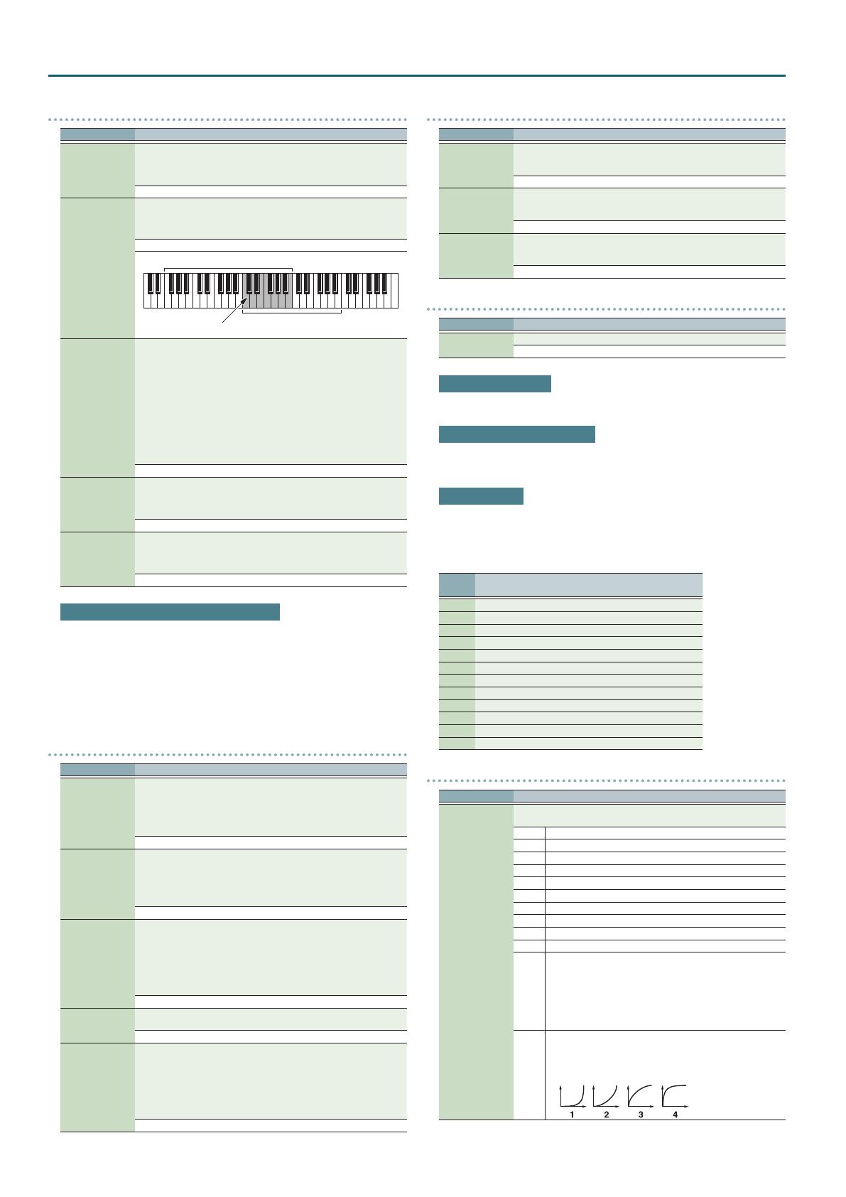
VC
Selects Velocity Curve for each MIDI channel one of the four
following Velocity Curve types that best matches the touch of the
connected MIDI keyboard.
Set this to “–” (OFF) if you are using the MIDI keyboard’s own
velocity curve.
1 / 1

Roland JUNO-DS61 User guide

Category
Musical Equipment
Type
User guide
This manual is also suitable for

Ask a question and I''ll find the answer in the document

Finding information in a document is now easier with AI

Ask the document