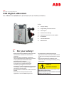
ABB VD4 Series Installation And Service Instructions Manual
- Type
- Installation And Service Instructions Manual
ABB VD4 Series
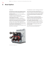
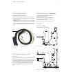
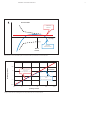
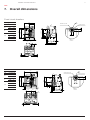
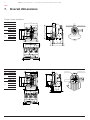
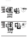
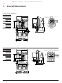
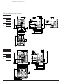
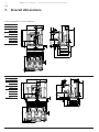
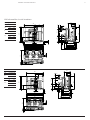
ABB VD4 Series digital circuit breaker is designed to provide a powerful electrical plant protection system. It uses current and voltage sensors to measure the current and voltage applied to each pole, providing accurate and reliable protection against faults. The VD4 Series is available in various voltage ratings and current capacities, making it suitable for a wide range of applications. It can be used in both fixed and withdrawable configurations, offering flexibility in installation and maintenance.
ABB VD4 Series
ABB VD4 Series digital circuit breaker is designed to provide a powerful electrical plant protection system. It uses current and voltage sensors to measure the current and voltage applied to each pole, providing accurate and reliable protection against faults. The VD4 Series is available in various voltage ratings and current capacities, making it suitable for a wide range of applications. It can be used in both fixed and withdrawable configurations, offering flexibility in installation and maintenance.


-
 1
1
-
 2
2
-
 3
3
-
 4
4
-
 5
5
-
 6
6
-
 7
7
-
 8
8
-
 9
9
-
 10
10
-
 11
11
-
 12
12
-
 13
13
-
 14
14
-
 15
15
-
 16
16
-
 17
17
-
 18
18
-
 19
19
-
 20
20
-
 21
21
-
 22
22


ABB VD4 Series Installation And Service Instructions Manual
- Type
- Installation And Service Instructions Manual
ABB VD4 Series
ABB VD4 Series digital circuit breaker is designed to provide a powerful electrical plant protection system. It uses current and voltage sensors to measure the current and voltage applied to each pole, providing accurate and reliable protection against faults. The VD4 Series is available in various voltage ratings and current capacities, making it suitable for a wide range of applications. It can be used in both fixed and withdrawable configurations, offering flexibility in installation and maintenance.
Ask a question and I''ll find the answer in the document
Finding information in a document is now easier with AI
Related papers
-
ABB VD4 17 Installation And Service Instructions Manual
-
-
-
-
-
-
-
-
-
Other documents
-
Cocoon HE180302 06/19, 11/19 Quick start guide
-
Fairchild High Flow Reversing Relay User manual
-
Plantronics Calisto 210 Owner's manual
-
Schneider Electric EvoPact HVX-O User guide
-
Seneca R203 Installation guide
-
VarTech PowerCube SFF PC Powerful and Versatile Rugged Compact PC User guide
-
AEG VB2 Plus User manual
-
Eaton 120W-VAC50 Instructions For Installation, Operation And Maintenance
-
 Micsig RCP500 User guide
-
Vetus VD6.170 User manual
