9
ENGLISH
Charging a Battery (Fig. C)
1. Plug the charger into an appropriate outlet before inserting
batterypack.
2. Insert the battery pack
27
into the charger, making sure the battery
pack is fully seated in the charger. The red (charging) light will blink
repeatedly indicating that the charging process hasstarted.
3. The completion of charge will be indicated by the red light remaining
ON continuously. The battery pack is fully charged and may be used
at this time or left in the charger. To remove the battery pack from the
charger, push the battery release button
28
on the batterypack.
NOTE: To ensure maximum performance and life of lithium-ion battery
packs, charge the battery pack fully before firstuse.
Charger Operation
Refer to the indicators below for the charge status of the batterypack.
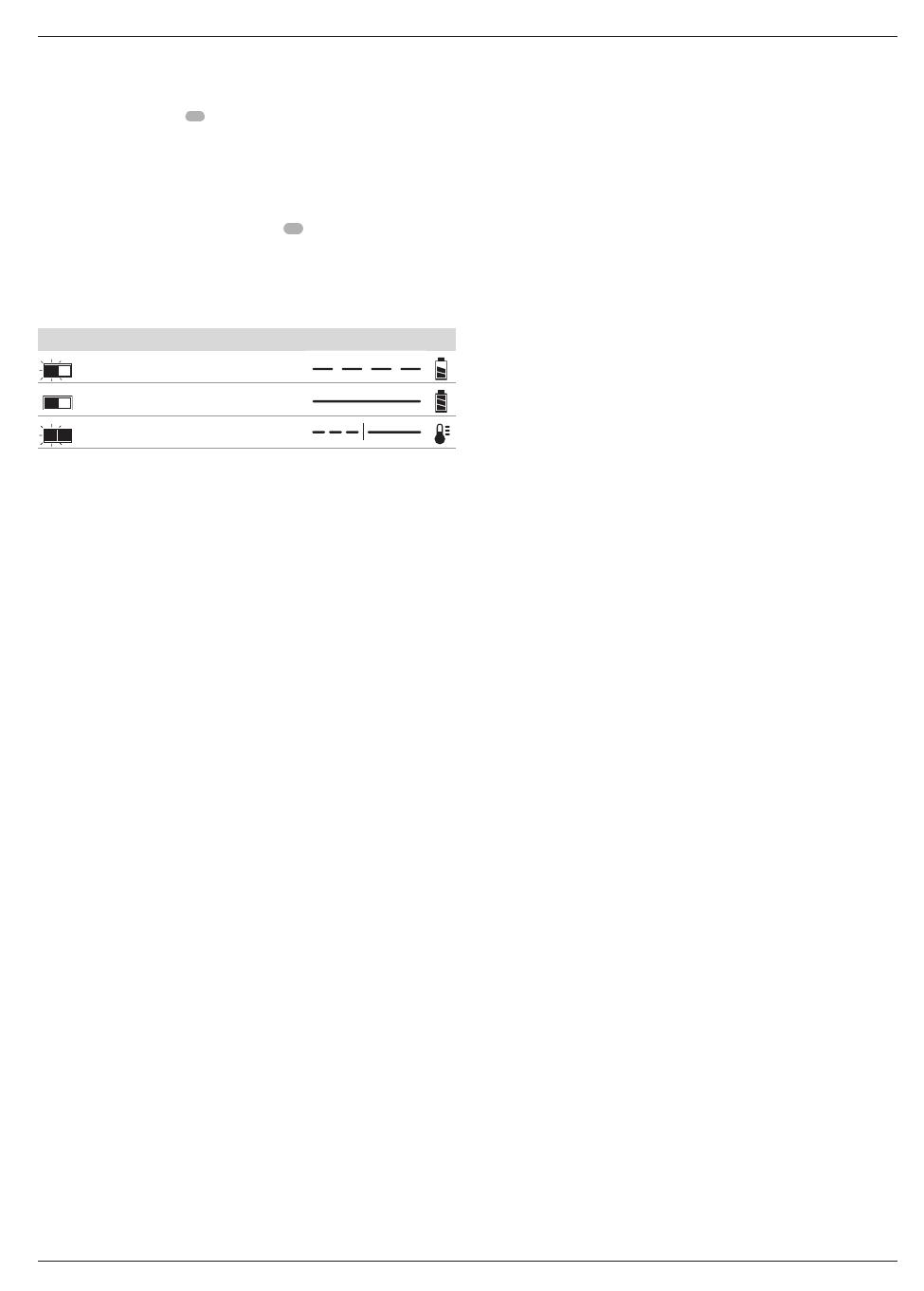
Charge Indicators
Charging
Fully Charged
Hot/Cold Pack Delay*
* The red light will continue to blink, but a yellow indicator light will be
illuminated during this operation. Once the battery pack has reached an
appropriate temperature, the yellow light will turn off and the charger will
resume the chargingprocedure.
The compatible charger(s) will not charge a faulty battery pack. The charger
will indicate faulty battery by refusing to light or by displaying problem
pack or charger blinkpattern.
NOTE: This could also mean a problem with acharger.
If the charger indicates a problem, take the charger and battery pack to be
tested at an authorised servicecentre.
Hot/Cold Pack Delay
When the charger detects a battery pack that is too hot or too cold, it
automatically starts a Hot/Cold Pack Delay, suspending charging until the
battery pack has reached an appropriate temperature. The charger then
automatically switches to the pack charging mode. This feature ensures
maximum battery packlife.
A cold battery pack will charge at a slower rate than a warm battery pack.
The battery pack will charge at that slower rate throughout the entire
charging cycle and will not return to maximum charge rate even if the
battery packwarms.
The DCB118 charger is equipped with an internal fan designed to cool
the battery pack. The fan will turn on automatically when the battery pack
needs to be cooled. Never operate the charger if the fan does not operate
properly or if ventilation slots are blocked. Do not permit foreign objects to
enter the interior of thecharger.
Electronic Protection System
XR Li-Ion tools are designed with an Electronic Protection System
that will protect the battery pack against overloading, overheating or
deepdischarge.
The tool will automatically turn off if the Electronic Protection System
engages. If this occurs, place the lithium-ion battery pack on the charger
until it is fullycharged.
Wall Mounting
These chargers are designed to be wall mountable or to sit upright on a
table or work surface. If wall mounting, locate the charger within reach of an
electrical outlet, and away from a corner or other obstructions which may
impede air flow. Use the back of the charger as a template for the location
of the mounting screws on the wall. Mount the charger securely using
drywall screws (purchased separately) at least 25.4mm long with a screw
head diameter of 7–9mm, screwed into wood to an optimal depth leaving
approximately 5.5mm of the screw exposed. Align the slots on the back of
the charger with the exposed screws and fully engage them in theslots.
Charger Cleaning Instructions
WARNING: Shock hazard. Disconnect the charger from the AC
outlet before cleaning. Dirt and grease may be removed from the
exterior of the charger using a cloth or soft non-metallic brush. Do not
use water or any cleaning solutions. Never let any liquid get inside the
tool; never immerse any part of the tool into aliquid.
Battery Packs
Important Safety Instructions for All Battery Packs
When ordering replacement battery packs, be sure to include catalog
number andvoltage.
The battery pack is not fully charged out of the carton. Before using the
battery pack and charger, read the safety instructions below. Then follow
charging proceduresoutlined.
READ ALL INSTRUCTIONS
• Do not charge or use battery in explosive atmospheres, such as
in the presence of flammable liquids, gases or dust. Inserting or
removing the battery from the charger may ignite the dust orfumes.
• Never force battery pack into charger. Do not modify battery pack
in any way to fit into a non-compatible charger as battery pack
may rupture causing serious personalinjury.
• Charge the battery packs only in DeWALTchargers.
• DO NOT splash or immerse in water or otherliquids.
• Do not store or use the tool and battery pack in locations where the
temperature may reach or exceed 40 ˚C (104 ˚F) (such as outside
sheds or metal buildings in summer).
• Do not incinerate the battery pack even if it is severely damaged
or is completely worn out. The battery pack can explode in a fire.
Toxic fumes and materials are created when lithium-ion battery packs
areburned.
• If battery contents come into contact with the skin, immediately
wash area with mild soap and water. If battery liquid gets into the
eye, rinse water over the open eye for 15 minutes or until irritation ceases.
If medical attention is needed, the battery electrolyte is composed of a
mixture of liquid organic carbonates and lithiumsalts.
• Contents of opened battery cells may cause respiratory irritation.
Provide fresh air. If symptoms persists, seek medicalattention.
WARNING: Burn hazard. Battery liquid may be flammable if exposed
to spark orflame.
WARNING: Never attempt to open the battery pack for any reason. If
battery pack case is cracked or damaged, do not insert into charger.
Do not crush, drop or damage battery pack. Do not use a battery pack
or charger that has received a sharp blow, been dropped, run over
or damaged in any way (i.e., pierced with a nail, hit with a hammer,
stepped on). Electric shock or electrocution may result. Damaged
battery packs should be returned to service centre forrecycling.
WARNING: Fire hazard. Do not store or carry the battery pack so
that metal objects can contact exposed battery terminals. For
example, do not place the battery pack in aprons, pockets, tool boxes,
product kit boxes, drawers, etc., with loose nails, screws, keys, etc.
CAUTION: When not in use, place tool on its side on a stable
surface where it will not cause a tripping or falling hazard. Some
tools with large battery packs will stand upright on the battery pack
but may be easily knockedover.
Transportation
WARNING: Fire hazard. Transporting batteries can possibly cause
fire if the battery terminals inadvertently come in contact with
conductive materials. When transporting batteries, make sure that the
battery terminals are protected and well insulated from materials that
could contact them and cause a shortcircuit.


