Page is loading ...

Copyright 2016
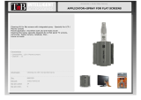
ISOBUS Product Control
Installation & Operation
Manual
016-0171-362 Rev. F 08/16 E28148

While every effort has been made to ensure the accuracy of this document,
Raven Industries assumes no responsibility for omissions and errors. Nor is any
liability assumed for damages resulting from the use of information contained
herein.
Raven Industries shall not be responsible or liable for incidental or consequential
damages or a loss of anticipated benefits or profits, work stoppage or loss, or
impairment of data arising out of the use, or inability to use, this system or any of
its components. Raven Industries shall not be held responsible for any
modifications or repairs made outside our facilities, nor damages resulting from
inadequate maintenance of this system.
As with all wireless and satellite signals, several factors may affect the availability
and accuracy of wireless and satellite navigation and correction services (e.g.
GPS, GNSS, SBAS, etc.). Therefore, Raven Industries cannot guarantee the
accuracy, integrity, continuity, or availability of these services and cannot
guarantee the ability to use Raven systems, or products used as components of
systems, which rely upon the reception of these signals or availability of these
services. Raven Industries accepts no responsibility for the use of any of these
signals or services for other than the stated purpose.
Disclaimer
©Raven Industries, Inc. 2009, 2011, 2012, 2013, 2014

Table of Contents
Manual No. 016-0171-362 Rev. F i
Calibration Reference Sheet .....................................................................................................3
Unit Definitions and Conversions ..............................................................................................4
Unit of Measure Definitions .................................................................................................4
Unit of Measure Conversions ..............................................................................................4
Chapter 1 Important Safety Information................................................. 1
Electrical Safety ...................................................................................................................1
Instructions for Wire Routing .....................................................................................................1
Instructions for Hose Routing ....................................................................................................2
Chapter 2 Introduction............................................................................. 5
Raven ISOBUS Product Control Node Kits ...............................................................................5
Updates .....................................................................................................................................6
Chapter 3 Installation............................................................................... 9
Mount the Flow Meter ...............................................................................................................9
Mount the Control Valve ..........................................................................................................10
By-Pass Plumbing .............................................................................................................10
Mount the Node ....................................................................................................................... 11
Install ISOBUS Product Control Cabling .................................................................................12
Mount the Foot Switch ............................................................................................................12
Implement Proximity Switch ....................................................................................................12
Chapter 4 ISOBUS Product Control Node Calibration........................ 13
Calibration Screen ...................................................................................................................14
Implement Calibration Tab ......................................................................................................15
Applicator Type ..................................................................................................................15
Total Width Display ............................................................................................................15
Section Setup ....................................................................................................................16
Product Control Calibration Tab ..............................................................................................17
Control Type ......................................................................................................................18
Meter Cal or Spreader Constant ........................................................................................18
Valve Delay .......................................................................................................................19
Tank or Bin Capacity .........................................................................................................19
Self Test Speed .................................................................................................................19
Speed Cal ..........................................................................................................................20
Pump RPM Cal ..................................................................................................................20
Valve Cal ...........................................................................................................................20
Tiered Boom Settings ........................................................................................................22
Spinner/Fan Control Setup ................................................................................................22
HP Pressure or HP Plus Control Setup .............................................................................23
Pulse Width Modulation Valve Setup .................................................................................25

Table of Contents
ii ISOBUS Product Control Installation & Operation Manual
Feature Settings ................................................................................................................29
Alarms Setup Tab ....................................................................................................................32
Low Tank ...........................................................................................................................32
Low Limit ...........................................................................................................................32
Off Rate Percent ................................................................................................................33
RPM Off Rate Percent (Granular Applications Only) .........................................................33
Dual Encoder Error Percent (Granular Applications Only) ................................................33
Bin Level Sensor (Granular Applications Only) .................................................................33
Low Limit Pressure Setting ................................................................................................33
Low Supply Pressure Setting (AccuFlow HP Plus Applications Only) ...............................33
Low Pressure Alarm (AccuFlow HP Applications Only) ....................................................33
Pump Fault Alarm (AccuFlow HP Plus Applications Only) ................................................33
Information ..............................................................................................................................34
Diagnostics ..............................................................................................................................34
Chapter 5 ISOBUS Product Control Operation ................................... 35
Product Control Home Screen ................................................................................................35
Quick Access Softkeys ......................................................................................................36
Remote Master Status .......................................................................................................37
Control Mode (Auto/Manual) .............................................................................................37
Application Speed ..............................................................................................................37
Pump RPM Cal (Spray Applicator) ....................................................................................38
Product Density (Granular Applications) ...........................................................................38
Target Pressure (NH3 Applications) ..................................................................................38
Pressure or Spinner/Fan RPM Display ..............................................................................39
Rates Area .........................................................................................................................40
Remaining Tank/Bin Volume ..............................................................................................41
Volume/Weight Applied .....................................................................................................41
Area Covered ....................................................................................................................42
Injection Pump Status Button ............................................................................................42
Section Status Display .......................................................................................................43
On-Screen Manual Section Controls .................................................................................43
Section Override ................................................................................................................44
Tiered Boom Status Display ..............................................................................................45
Tally Registers .........................................................................................................................45
Field Area and Volume ......................................................................................................46
Total Area and Volume ......................................................................................................46
Distance .............................................................................................................................46
Volume per Minute Display ................................................................................................46
Area per Hour Display .......................................................................................................46

Table of Contents
Manual No. 016-0171-362 Rev. F iii
Chapter 6 Troubleshooting ................................................................... 47
Appendix 7 System Diagrams.................................................................. 49
Appendix 8 Calculating the Calibration Values...................................... 59
Section Widths ........................................................................................................................59
Broadcast ..........................................................................................................................59
Band ..................................................................................................................................59
Rate Cal ..................................................................................................................................59
Tiered Boom Settings ..............................................................................................................60
Valve Cal .................................................................................................................................62
Valve Backlash Digit ..........................................................................................................62
Valve Speed Digit ..............................................................................................................62
Brake Point Digit ................................................................................................................62
Dead Band Digit ................................................................................................................62
Valve Cal 2 ........................................................................................................................63
Flow Cal (Dual Loop Control Mode) ..................................................................................63
Sgain (Pressure System Gain - Dual Loop Control Mode) ................................................63
Spreader Constant ..................................................................................................................64
Standard Rate display .......................................................................................................64
Metric Rate Display ...........................................................................................................64
Verification of Spreader Constant ......................................................................................64
Spinner RPM ...........................................................................................................................66
Valve Type .........................................................................................................................66
RPM Meter Cal ..................................................................................................................67
RPM Target .......................................................................................................................67
Appendix 2 Flow Meter Maintenance and Adjustment Procedure......... v
Flow Meter Maintenance ...........................................................................................................v
Testing Flow Meter Cables ........................................................................................................v
Testing the Flow Meter/Encoder Cable ...............................................................................v
Procedure to Recalibrate Flow Meter .......................................................................................vi

Table of Contents
iv ISOBUS Product Control Installation & Operation Manual

Manual No. 016-0171-362 Rev. F vii
CALIBRATION REFERENCE SHEET
Record the settings and calibration values used when programming the field computer and keep this sheet for
future reference or when contacting a service technician.
Circle the setting selected on the field computer for the following options:
Write down the calculated calibration values in the spaces provided.
UNITS
US (Acres) SI (Hectares) Turf (1000 Square Feet)
CONTRO
L TYPE
Liquid Sprayer
Gran 1
(Single belt bed)
Gran 2
(Split belt bed,
single encoder)
Gran 3
(Split belt bed,
dual encoders)
Spinner RPM
Control
VALVE
TYPE
Standard Valve Fast Valve Fast Close Valve PWM Valve
PWM Close
Valve
Boom Widths
(Boom Cal)
Meter Cal Rate Cal Valve Cal
Volume in
Tank/Bin
1. 1. 1. 1. 1.
2. 2. 2. 2. 2.
3. 3. 3. 3. 3.
4. 4. 4. 4. 4.
5.
6.
7.
8.
9.
10.
11.
12.
13.
14.
15.
16.

CHAPTER 1
viii ISOBUS Product Control Installation & Operation Manual
UNIT DEFINITIONS AND CONVERSIONS
UNIT OF MEASURE DEFINITIONS
UNIT OF MEASURE CONVERSIONS
To convert the METER CAL value into the selected unit of measure, divide the original number printed on the Flow
Meter label by the desired conversion value.
Density
(Granular
Only)
Spreader
Constant
(Granular
Only)
1. 1.
2. 2.
3. 3.
4. 4.
Abbreviation Definition Abbreviation Definition
GPM Gallons per Minute dm Decimeters
lit/min Liters per Minute m Meter
dl/min Deciliters per Minute MPH Miles per Hour
PSI Pounds per Square Inch km Kilometers
kPa Kilopascal km/h Kilometers per Hour
GPA Gallons per Acre US Volume per Acre
lit/ha Liters per Hectare SI Volume per Hectare
ml/ha Milliliters per Hectare TU Volume per 1,000 Square Feet
GPK Gallons per 1,000 Square Feet [ ] Metric Numbers
mm Millimeters lb/acre Pounds per Acre
cm Centimeters kg/ha Kilograms per Hectare
Fluid Ounces Conversion
Formula
Liters Conversion Formula Pounds Conversion Formula
Original METER CAL Number
128
Original METER CAL Number
3.785
Original METER CAL Number
Weight of One Gallon of Product

Manual No. 016-0171-362 Rev. F ix
Liquid Area
• 1 U.S gallon = 128 fluid ounces • 1 square meter = 10.764 square feet
• 1 U.S. gallon = 3.785 liters • 1 hectare = 2.471 acres or 10,000 square meters
• 1 U.S. gallon = 0.83267 imperial gallons • 1 acre = 0.405 hectares or 43,560 square feet
• 1 U.S. gallon = 8.34 pounds (water) • 1 square mile = 640 acres or 258.9 hectares
Length Pressure
• 1 millimeter (mm) = 0.039 inches • 1 psi = 6.89 kPa
• 1 centimeter (cm) = 0.393 inches • 1 kPa = 0.145 psi
• 1 meter (m) = 3.281 feet
Weight
• 1 kilometer (km) = 0.621 miles • 1 Pound = 16 Ounces
• 1 inch = 25.4 mm or 2.54 cm • 1 Pound = 0.45 Kilograms
• 1 mile = 1.609 km

CHAPTER 1
x ISOBUS Product Control Installation & Operation Manual

CHAPTER
1
Manual No. 016-0171-362 Rev. F 1
CHAPTER 1
IMPORTANT SAFETY
INFORMATION
Read this manual carefully before installing the Raven ISOBUS node.
• Follow all safety information presented within this manual.
• If you require assistance with any portion of the installation or service of your Raven equipment, contact a local
Raven dealer for support.
When operating the machine after installing the Raven ISOBUS node, observe the following safety measures:
• Be alert and aware of surroundings.
• Do not operate any agricultural equipment while under the influence of alcohol or an illegal substance.
• Determine and remain a safe working distance from other individuals. The operator is responsible for disabling
product control when a safe working distance has diminished.
Please review the operation and safety instructions included with your implement and/or controller.
ELECTRICAL SAFETY
Do not reverse power leads. Doing so could cause severe damage to the equipment. Always make sure that the
power leads are connected to the correct polarity as marked. Ensure that the power cable is the last cable to be
connected.
INSTRUCTIONS FOR WIRE ROUTING
The word harness is used to mean all electrical leads and cables, bundled and unbundled. When installing harness,
secure it at least every 30 cm (12in) to the frame. Follow existing harness as much as possible and use these
guidelines:
Harness should not contact or be attached to:
• Lines and hoses with high vibration forces or pressure spikes
• Lines and hoses carrying hot fluids beyond harness component specifications
Avoid contact with any sharp edge or abrading surfaces such as, but not limited to:
NOTICE
CAUTION

CHAPTER 1
2 ISOBUS Product Control Installation & Operation Manual
• Sheared or flame cut edges
• Edges of machined surfaces
• Fastener threads or cap screw heads
• Ends of adjustable hose clamps
• Wire exiting conduit without protection, either ends or side of conduit
• Hose and tube fittings
Routing should not allow harnesses to:
• Hang below the unit
• Have the potential to become damaged due to exposure to the exterior environment. (i.e. tree limbs, debris,
attachments)
• Be placed in areas of or in contact with machine components which develop temperatures higher than the
temperature rating of harness components
• Wiring should be protected or shielded if it needs to route near hot temperatures beyond harness component
specifications
Harnessing should not have sharp bends
Allow sufficient clearance from machine component operational zones such as:
• Drive shafts, universal joints and hitches (i.e. 3-point hitch)
• Pulleys, gears, sprockets
• Deflection and backlash of belts and chains
• Adjustment zones of adjustable brackets
• Changes of position in steering and suspension systems
• Moving linkages, cylinders, articulation joints, attachments
• Ground engaging components
For harness sections that move during machine operation:
• Allow sufficient length for free movement without interference to prevent: pulling, pinching, catching or
rubbing, especially in articulation and pivot points
• Clamp harnesses securely to force controlled movement to occur in the desired harness section
• Avoid sharp twisting or flexing of harnesses in short distances
• Connectors and splices should not be located in harness sections that move
Protect harnesses from:
• Foreign objects such as rocks that may fall or be thrown by the unit
• Buildup of dirt, mud, snow, ice, submersion in water and oil
• Tree limbs, brush and debris
• Damage where service personnel or operators might step or use as a grab bar
• Damage when passing through metal structures
•High pressure wash
INSTRUCTIONS FOR HOSE ROUTING
The word hoses is used to mean all flexible fluid carrying components. Follow existing hoses as much as possible
and use these guidelines:

Manual No. 016-0171-362 Rev. F 3
IMPORTANT SAFETY INFORMATION
Hoses should not contact or be attached to:
• Components with high vibration forces
• Components carrying hot fluids beyond hoses component specifications
Avoid contact with any sharp edge or abrading surfaces such as, but not limited to:
• Sheared or flame cut edges
• Edges of machined surfaces
• Fastener threads or cap screw heads
• Ends of adjustable hose clamps
Routing should not allow hoses to:
•Hang below the unit
• Have the potential to become damaged due to exposure to the exterior environment. (i.e. tree limbs, debris,
attachments)
• Be placed in areas of or in contact with machine components which develop temperatures higher than the
temperature rating of hose components
• Hoses should be protected or shielded if it needs to route near hot temperatures beyond hose component
specifications
Hoses should not have sharp bends
Allow sufficient clearance from machine component operational zones such as:
• Drive shafts, universal joints and hitches (i.e. 3-point hitch)
• Pulleys, gears, sprockets
• Deflection and backlash of belts and chains
• Adjustment zones of adjustable brackets
• Changes of position in steering and suspension systems
• Moving linkages, cylinders, articulation joints, attachments
• Ground engaging components
For hose sections that move during machine operation:
• Allow sufficient length for free movement without interference to prevent: pulling, pinching, catching or
rubbing, especially in articulation and pivot points
• Clamp hoses securely to force controlled movement to occur in the desired hose section
• Avoid sharp twisting or flexing of hoses in short distances
Protect hoses from:
• Foreign objects such as rocks that may fall or be thrown by the unit
• Buildup of dirt, mud, snow, ice, submersion in water and oil
• Tree limbs, brush and debris
• Damage where service personnel or operators might step or use as a grab bar
• Damage when passing through metal structures
• High pressure wash

CHAPTER 1
4 ISOBUS Product Control Installation & Operation Manual

CHAPTER
2
Manual No. 016-0171-362 Rev. F 5
CHAPTER 2
INTRODUCTION
The Raven ISOBUS single product control node is designed to add liquid or granular speed compensated product
control capabilities to ISOBUS virtual terminals. Adding the Raven ISOBUS product control node will allow a
machine operator to monitor and control a Raven product control system directly from a virtual terminal (VT)
display.
NOTE: Prior to using the product control feature with your VT display, the ISOBUS node must be calibrated
for the product control system. See Chapter 5, ISOBUS Product Control Operation, for more
information.
This manual assumes the required control hardware has already been installed on a specific
implement and is properly connected and wired.
RAVEN ISOBUS PRODUCT CONTROL NODE KITS
This section contains a list of kit contents which should have been supplied with the ISOBUS product control node.
Before installing the Raven ISOBUS node, compare the items in the kit with the list. If you have questions regarding
your kit, contact a local Raven dealer.
NOTE: A Raven ISOBUS hitch cable is required to connect the Raven ISOBUS product control node to the VT
display and ISOBUS system. Depending upon the specific machine, this cable may be installed from
the factory or must be ordered separately. Refer to Figure 1 on page 49 or contact a local Raven
dealer for more information.
TABLE 1. ISOBUS Single Product (Liquid/Granular) Node Kit
(16-Pin Product Cable) (P/N 117-6100-001)
NOTE: A 21’ spinner control cable (P/N 115-0171-880) is required if the ISOBUS product control system will be
utilized for spinner control applications.
TABLE 2.
Description Part Number Qty.
Terminator, Active CAN Powell 063-0172-964 1
Node, ISOBUS Single Product 063-0173-006 1
Switch, ISO Node Foot 063-0173-080 1
Cable, Main Node 115-0171-949 1
Cable, Cab Foot Switch, 8’ 115-0171-865 1
Cable, ISO Powell Terminator Adapter 115-0171-963 1

CHAPTER 2
6 ISOBUS Product Control Installation & Operation Manual
TABLE 3. ISOBUS Single Product (Liquid/Granular) Node Kit
(37-Pin Product Cable) (P/N 117-6100-002)
NOTE: A 21’ spinner control cable (P/N 115-0171-880) is required if the ISOBUS product control system will be
utilized for spinner control applications.
TABLE 5. ISOBUS Single Product (Liquid/Granular) Node Kit
(22-Pin Product Cable) (P/N 117-6100-003)
NOTE: A 21’ spinner control cable (P/N 115-0171-880) is required if the ISOBUS product control system will be
utilized for spinner control applications.
UPDATES
Updates for Raven manuals as well as software updates for Raven consoles are available at the Applied Technology
Division web site:
www.ravenhelp.com
TABLE 4.
Description Part Number Qty.
Terminator, Active CAN Powell 063-0172-964 1
Node, ISOBUS Single Product 063-0173-006 1
Switch, ISO Node Foot 063-0173-080 1
Cable, Main Node 115-0171-945 1
Cable, Cab Foot Switch, 8’ 115-0171-865 1
Cable, ISO Powell Terminator Adapter 115-0171-963 1
TABLE 6.
Description Part Number Qty.
Terminator, Active CAN Powell 063-0172-964 1
Node, ISOBUS Single Product 063-0173-006 1
Switch, ISO Node Foot 063-0173-080 1
Cable, 37-pin to 22-pin Adapter 115-0171-864 1
Cable, Main Node 115-0171-945 1
Cable, Cab Foot Switch, 8’ 115-0171-865 1
Cable, ISO Powell Terminator Adapter 115-0171-963 1

2
Manual No. 016-0171-362 Rev. F 7
INTRODUCTION
Sign up for e-mail alerts to receive notifications when updates for your Raven products are available on the Raven
web site.
At Raven Industries, we strive to make your experience with our products as rewarding as
possible. One way to improve this experience is to provide us with feedback on this manual.
Your feedback will help shape the future of our product documentation and the overall service we
provide. We appreciate the opportunity to see ourselves as our customers see us and are eager
to gather ideas on how we have been helping or how we can do better.
To serve you best, please send an email with the following information to
techwriting@ravenind.com
-ISOBUS Product Control Installation & Operation Manual
-Manual No. 016-0171-362 Rev. F
-Any comments or feedback (include chapter or page numbers if applicable).
-Let us know how long have you been using this or other Raven products.
We will not share your email or any information you provide with anyone else. Your feedback is
valued and extremely important to us.
Thank you for your time.

CHAPTER 2
8 ISOBUS Product Control Installation & Operation Manual

CHAPTER
3
Manual No. 016-0171-362 Rev. F 9
CHAPTER 3
INSTALLATION
MOUNT THE FLOW METER
1. Mount the flow meter in the area of the boom valves as shown in Figure 1. All flow through the flow meter must
go to the booms, (i.e. no return line to tank or pump after flow meter).
2. Mount the flow meter horizontal to the ground.
3. For best results, allow a minimum of 7-1/2” [20 cm] of straight hose on inlet of flow meter. Bend radius of hose
on outlet of flow meter should be gradual.
4. Flow must be in direction of arrow on flow meter.
FIGURE 1. Flow Control System
To ISObus
Control Harness
To sections 6 through 16

CHAPTER 3
10 ISOBUS Product Control Installation & Operation Manual
MOUNT THE CONTROL VALVE
1. Mount the motorized control valve in the main hose line between the flow meter and the booms, with the
motor housing in the upright position. Refer to Figure 1 on page 9.
2. Connect the flow control cable connectors to the boom valves, flow meter, and motorized control valve. The
table below tells white wire color(s) connect to each valve:
BY-PASS PLUMBING
For flow less than 3 GPM [11 lit/min] the motorized control valve must be mounted in a by-pass line.
Wire Colors Labeled
Connect to
Valve
Black or
Gray
Valve #1 1
Brown Valve #2 2
Blue Valve #3 3
Black with white stripe Valve #4 4
Brown with a white stripe Valve #5 5
Blue with a white stripe Valve #6 6
White with a black stripe Valve #7 7
White with a brown stripe Valve #8 8
White with a blue stripe Valve #9 9
Pink or
Violet
Valve #10 10
Yellow with a white stripe or
Gray
Valve #11 11
Green with white stripe or
Brown
Valve #12 12
Red with white stripe or
Blue
Valve #13 13
White with yellow stripe or
Black with white stripe
Valve #14 14
White with a green stripe or
Brown with a white stripe
Valve #15 15
White with a red stripe or
Blue with a white stripe
Valve #16 16
/