Page is loading ...

FocusPRO
®
TH6000 Series
Programmable Thermostat
® U.S. Registered Trademark. Patents pending.
Copyright © 2009 Honeywell International Inc.
All rights reserved.
Installation
Guide
Must be installed by a trained, experienced technician
Read these instructions carefully. Failure to follow these instructions
can damage the product or cause a hazardous condition.
Need Help?
For assistance with this product please visit http://customer.honeywell.com
or call Honeywell Customer Care toll-free at 1-800-468-1502
69-1920EFS-01
This manual covers the following models
• TH6110D:For1Heat/1Coolsystems
• TH6220D:Forupto2Heat/2Coolsystems
• TH6320U:Forupto3Heat/2Coolsystems
(Remove battery holder to find model number)
System Types
• Gas,oil,orelectricheatwithair
conditioning
• Warmair,hotwater,high-
efficiencyfurnaces,heatpumps,
steam,gravity
• Heatonly—two-wiresystems,
three-wire zone valves (Series
20),andnormallyopenzone
valves
• Heatonlywithfan
• Coolonly
• 750mVheatingsystems

Installation Guide
69-1920EFS—01 2
ENGLISH
MCR29435
M29433
Wallplate installation
1. Separate wallplate from thermostat.
2. Mount wallplate as shown below.
Drill3/16"holesfordrywall.Drill7/32"holesforplaster.
Wallanchors
Wallplate
Wirehole
Mounting screws
CAUTION: ELECTRICAL HAZARD
Cancauseelectricalshockorequipmentdamage.Disconnectpowerbefore
beginning installation.
MERCURY NOTICE
Ifthisproductisreplacingacontrolthatcontainsmercuryinasealedtube,donot
place the old control in the trash. Contact your local waste management authority for
instructions regarding recycling and proper disposal.
Pull here to remove wallplate
from new thermostat.
Remove battery holder. Insert reference card after wallplate is
mounted(seeinstructions,below).
It's easier to grasp the wallplate
and remove it after completely
removing the battery holder.
MCR29434

FocusPRO
®
TH6000 Series
3 69-1920EFS—01
ENGLISH
MCR29436
Power options
Keep wires in this
shaded area
Connect C for primary AC power
(optional if batteries are installed).
Insert batteries for primary
or backup power.
Remove factory-
installed jumper
only for two-
transformer
systems.
Conventional Terminals:
Rc 24VACpowerfromcooling
transformer
R 24VACpowerfromheating
transformer
W Heat relay (stage 1)
W2 Heat relay (stage 2)
Y Compressor contactor (stage 1)
Y2 Compressor contactor (stage 2)
G Fan relay
C 24VACcommon.For2transformer
systems,usecommonwirefromcooling
transformer.
Heat Pump Terminals:
Rc 24VACpowerfromcooling
transformer
R 24VACpowerfromheating
transformer
O/B Changeover valve
Y Compressor contactor (stage 1)
Y2 Compressor contactor (stage 2)
-TH6320U only
G Fan relay
Aux Auxiliary heat relay*
E Emergency heat relay*
L Sends output when set to Em. Heat
C 24VACcommon
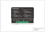
Wiring
Terminal designations
Shaded areas below apply only to TH6320U/TH6220D or as otherwise noted.
*Aux and E terminals combined on TH6320U only.
TH6110D
RcYWGRC
TH6220D
RcYWGW2Y2 RC
TH6320U
RcYWGW2Y2 RC
MCR29437
TH6110D
RcYGRC
RcY
GAuxELRC
TH6220D
RcYGAux
E
Y2LRC
TH6320U
MCR29438

Installation Guide
69-1920EFS—01 4
ENGLISH
Wiring
Wiring guide — conventional systems
Shaded areas below apply only to TH6320U/TH6220D or as otherwise noted.
NOTES
Wirespecifications:
Use 18- to 22-gauge thermostat wire.
Shielded cable is not required.
[1] Power supply. Provide disconnect means and
overload protection as required.
[2] Remove jumper for 2-transformer systems.
[3] Optional24VACcommonconnection.
[4] Common connection must come from cool-
ing transformer.
[5] InInstallerSetup,setsystemtypetoHeat Only.
[6] InInstallerSetup,setsystemtypeto
2Heat/2Cool Conventional.
[7] InInstallerSetup,setchangeovervalvetoO
or B.
[8] InInstallerSetup,setsystemtypeto
2Heat/1Cool Heat Pump.
[9] InInstallerSetup,setsystemtypeto
2Heat/2Cool Heat Pump.
[10] InInstallerSetup,setsystemtypeto
3Heat/2CoolHeatPump.
[11] L terminal sends a continuous output when
thermostat is set to Em. Heat. Connect to
Honeywell zoning panels to switch the panel
to Emergency Heat.
[12] Install field jumper between Aux and E if
there is no emergency heat relay.
1H/1C System
(1 transformer)
Rc Power [1]
R [R+Rc joined by jumper]
Y Compressor contactor
C 24VACcommon[3]
W Heat relay
G Fan relay
Heat-only System
Rc Power [1]
R [R+Rc joined by jumper]
C 24VACcommon[3]
W Heat relay
Heat-only System
(Series 20) [5]
Rc [R+Rc joined by jumper]
R Series 20 valve terminal “R” [1]
Y Series20valveterminal“W”
C 24VACcommon[3]
W Series 20 valve terminal “B”
Heat-only System
(normally open zone valve) [5]
Rc [R+Rc joined by jumper]
R Power [1]
Y Normally open zone valve
C 24VACcommon[3]
1H/1C System
(2 transformers)
Rc Power (cooling transformer) [1,2]
R Power (heating transformer) [1,2]
Y Compressor contactor
C 24VACcommon[3,4]
W Heat relay
G Fan relay
Heat-only System
with Fan
Rc Power [1]
R [R+Rc joined by jumper]
C 24VACcommon[3]
W Heat relay
G Fan relay
Cool-only System
Rc Power [1]
R [R+Rc joined by jumper]
Y Compressor contactor
C 24VACcommon[3]
G Fan relay
2H/2C System
(1 transformer) [6]
Rc Power [1]
R [R+Rc joined by jumper]
Y Compressor contactor (stage 1)
C 24VACcommon[3]
W Heat relay (stage 1)
G Fan relay
W2 Heat relay (stage 2)
Y2 Compressor contactor (stage 2)
2H/2C System
(2 transformers) [6]
Rc Power (cooling transformer)[1,2]
R Power (heating transformer) [1,2]
Y Compressor contactor (stage 1)
C 24VACcommon[3,4]
W Heat relay (stage 1)
G Fan relay
W2 Heat relay (stage 2)
Y2 Compressor contactor (stage 2)
See [notes] below
RcYWG RC
MCR29439
RcWRC
MCR29440
RcYWRC
MCR29441
RcYRC
MCR29442
RcWG RC
MCR29444
RcYG RC
MCR29445
RcYWGW2Y2 RC
MCR29446
RcYWG RC
M29443
RcYWGW2Y2 RC
M29447

FocusPRO
®
TH6000 Series
5 69-1920EFS—01
ENGLISH
MCR29453
Wiring
Wiring guide — heat pump systems
Shaded areas below apply only to TH6320U/TH6220D or as otherwise noted.
Thermostat mounting
Align the 4 tabs on the wallplate with
slotsonthebackofthethermostat,
then push gently until the thermostat
snaps in place.
Push excess wire back into
the wall opening.
Plug wall opening with
non-flammable insulation.
1H/1C Heat
Pump System
Rc Power [1]
R [R+Rc joined by jumper]
Y Compressor contactor
C 24VACcommon[3]
O/B Changeover valve [7]
G Fan relay
2H/1C Heat
Pump System
(TH6220D only) [8]
Rc Power [1]
R [R+Rc joined by jumper]
Y Compressor contactor
C 24VACcommon[3]
O/B Changeover valve [7]
G Fan relay
Aux Auxiliary heat relay [12]
E Emergency heat relay [12]
L Sends output when set to Em. Heat [11]
2H/1C Heat
Pump System
(TH6320U only) [8]
Rc Power [1]
R [R+Rc joined by jumper]
Y Compressor contactor
C 24VACcommon[3]
O/B Changeover valve [7]
G Fan relay
Aux/E Auxiliary/Emergency heat relay
L Sends output when set to Em. Heat [11]
2H/2C Heat
Pump System
(TH6320U only) [9]
Rc Power [1]
R [R+Rc joined by jumper]
Y Compressor contactor (stage 1)
C 24VACcommon[3]
O/B Changeover valve[7]
G Fan relay
Y2 Compressor contactor (stage 2)
L Sends output when set to Em. Heat [11]
3H/2C Heat
Pump System
(TH6320U only) [10]
Rc Power [1]
R [R+Rc joined by jumper]
Y Compressor contactor (stage 1)
C 24VACcommon[3]
O/B Changeover valve [7]
G Fan relay
Aux/E Auxiliary/Emergency heat relay
Y2 Compressor contactor (stage 2)
L Sends output when set to Em. Heat [11]
See [notes] on page 4.
MCR29448
RcY
GRC
RcYGAuxELRC
MCR29449
RcYGAux
E
LRC
MCR29450
RcYGY2LRC
MCR29451
RcYGAux
E
LRCY2
MCR29452

Installation Guide
69-1920EFS—01 6
ENGLISH
1
0
Done Next
MCR29454
Tobegin,press and hold the s and FAN
buttons until the display changes.
Function
number
Setting
Press s or t to change settings.
Press NEXT to advance to the next function.
PressDONEtoexitandsavesettings.
Installer setup
Follow the procedure below to configure the thermostat to match the installed
heating/coolingsystem,andcustomizefeatureoperationasdesired.
Continued on next page
Setup function Settings & options (factory default in bold)
Shaded areas below apply only to TH6320U/TH6220D or as otherwise noted.
*[Othercyclerateoptions:2,4,6,7,8,10,11or12CPH]
1 System type 0 1 heat/1 cool conventional
1 1 heat/1 cool heat pump (no aux. heat)
2 Heatonly—2-wiresystems,3-wirezonevalves(Series20),and
normally open zone valves
3 Heatonlywithfan
4 Cool only
5 2 heat/1 cool heat pump (with aux. heat)
6 2 heat/2 cool conventional
7 2heat/1coolconventional
8 1 heat/2 cool conventional
9 2 heat/2 cool heat pump (no aux. heat) - TH6320U only
10 3heat/2coolheatpump(withaux.heat)-TH6320U only
2 Changeover valve
(O/B terminal)
0 Changeover valve (O/B terminal energized in cooling)
1 Changeover valve (O/B terminal energized in heating)
3 Fan control
(heating)
0 Gas or oil furnace — equipment controls fan in heating
1 Electricfurnace—thermostatcontrolsfaninheating
5 Stage 1 heat cycle
rate (CPH: cycles/hour)*
5 For gas or oil furnaces of less than 90% efficiency
1 For steam or gravity systems
3 Forhotwatersystems&furnaces of over 90% efficiency
9 For electric furnaces
6 Stage 2 heat cycle
rate/Auxiliary heat
cycle rate (CPH)*
5 For gas or oil furnaces of less than 90% efficiency
1 For steam or gravity systems
3 Forhotwatersystems&furnaces of over 90% efficiency
9 For electric furnaces
7 Auxiliary heat cycle
rate (CPH)*
Only TH6320U
for 3H/2C Heat Pumps
5 For gas or oil furnaces of less than 90% efficiency
1 For steam or gravity systems
3 Forhotwatersystems&furnaces of over 90% efficiency
9 For electric furnaces
8 Emergency heat cycle
rate (CPH)*
9 For electric emergency heat
1 For steam or gravity systems
3 Forhotwatersystems&furnaces of over 90% efficiency
5 For gas or oil furnaces of less than 90% efficiency

FocusPRO
®
TH6000 Series
7 69-1920EFS—01
ENGLISH
10
0
MCR29455
System test System status
Shaded areas below apply only to TH6320U/TH6220D or as otherwise noted.
Press s / t to turn system on/off.
Press NEXT to advance to next test.
PressDONEtoterminatesystemtest.
Test number System status
Tobegin,press and hold the s and t
buttons until the display changes.
Installer setup
Setup function Settings & options (factory default in bold)
Shaded areas below apply only to TH6320U/TH6220D or as otherwise noted.
9 Stage 1 compressor
cycle rate (CPH)
3 Recommended for most compressors
[Othercyclerateoptions:1,2,4,5or6CPH]
10 Stage 2 compressor
cycle rate (CPH)
3 Recommended for most compressors
[Othercyclerateoptions:1,2,4,5or6CPH]
12 Manual/Auto
changeover
0 Manual changeover (Heat/Cool/Off)
1 Auto changeover (Heat/Cool/Auto/Off) **See page 8
2 Auto changeover only (Auto) **See page 8
13 Adaptive Intelligent
Recovery™
1 On**See page 8
0 Off
14 Temperature
display
0 Fahrenheit
1 Celsius
15 Compressor
protection
5 Five-minute compressor off time **See page 8
[Otheroptions:0,1,2,3or4-minuteofftime]
16 Schedule format 0 5/2 (programmable weekdays and weekends)
1 5/1/1(weekdays,Saturday&Sundayprogrammable)
27 Heat temperature
range stops
90 Max. heat temperature setting is 90° F (32° C)
[Other options: 40 °F to 89 °F (4.5 °Cto31.5°C)]
28 Cool temperature
range stops
50 Min. cool temperature setting is 50° F (10° C)
[Other options: 51 °F to 99 °F (10.5 °Cto37°C)]
Installer system test
10 Heating system 0 Heat and fan turn off.
1 Stage1heatturnson.FanturnsonifSetupFunction1issetto1,
5,9or10ORSetupFunction3issetto1**Seepage6
2 Stage 2 heat turns on
3 Stage3heatturnson-TH6320U only
20 Emergency heating
system
0 Heat and fan turn off
1 Heat and fan turn on
2 Stage 2 heat turns on (auxiliary heat) - TH6220D only
30 Cooling system 0 Compressor and fan turn off
1 Compressor and fan turn on
2 Stage 2 compressor turns on
40 Fan system 0 Fan turns off
1 Fan turns on
CAUTION: Compressor protection is bypassed during testing. To prevent equipment
damage,avoidcyclingthecompressorquickly.

Installation Guide
Honeywell International Inc.
1985DouglasDriveNorth
GoldenValley,MN55422
http://customer.honeywell.com
Automation and Control Solutions
® U.S. Registered Trademark.
© 2009 Honeywell International Inc.
69-1920EFS—01M.S.05-09
Honeywell Limited-Honeywell Limitée
35DynamicDrive
Toronto,OntarioM1V4Z9
Printed in U.S.A. on recycled
paper containing at least 10%
post-consumer paper fibers.
Special functions
Auto Changeover(SetupFunction12):WhensettoAuto,thethermostatautomaticallyselects
heating or cooling depending on the indoor temperature. The thermostat will automatically
adjustheatandcoolsettingstomaintaina3-degreeseparation(fixed).Note:IfyouselectAuto
Changeover Only,theSystemSettingonthethermostatwillstaylockedintheAutoposition,
preventingtheuserfromchangingittoEmHeat,Heat,CoolorOff.
Adaptive Intelligent Recovery™(SetupFunction13):Allowsthethermostatto“learn”how
longthefurnaceandairconditionertaketoreachprogrammedtemperaturesettings,sothe
temperature is reached at the scheduled time.
Compressor Protection (Setup Function 15): Forces the compressor to wait a few minutes
beforerestarting,topreventdamage.Duringthewaittime,themessageCoolOnorHeatOn
(heat pumps only) will flash on the display.
Accessories & replacement parts
Please contact your distributor to order replacement parts.
Battery holder ............................PartNumber50007072-001
Cover plate assembly* .....................PartNumber50002883-001
12 pack of medium cover plates* ............PartNumber50007298-001
*Use to cover marks left by old thermostats.
Specifications
Temperature Ranges
• Heat:40°to90°F(4.5°to32°C)
• Cool:50°to99°F(10°to37°C)
Operating Ambient Temperature
• 32°to120°F(0°to48.9°C)
Shipping Temperature
• -20°to120°F(-28.9°to48.9°C)
Operating Relative Humidity
• 5%to90%(non-condensing)
Physical Dimensions
• 3-9/16"Hx5-13/16"Wx1-1/2"D
91mmHx147mmWx38mmD
Electrical Ratings
Terminal Voltage(50/60Hz) RunningCurrent
WHeating 20-30Vac 0.02-1.0A
(Powerpile) 750mVDC 100mADC
W2(Aux)Heating 20-30Vac 0.02-0.5A
YCooling 20-30Vac 0.02-1.0A
Y2Cooling 20-30Vac 0.02-1.0A
GFan 20-30Vac 0.02-0.5A
O/BChangeover 20-30Vac 0.02-0.5A
EEmergencyheat 20-30Vac 0.02-1.0A
LOutput 20-30Vac 0.02-0.5A
/