Page is loading ...

Original Instructions
Ed.10/13 Cod. 3019988
English MATIC 750

2
CEMB S.p.a. - Via Risorgimento, 9 - 23826 Mandello del Lario (LC) - ITALY
which this statement refers to meets the following directive
as well as the following:
Mandello del Lario, 14/06/12
Crossage EVO
EN 12100 - EN 60204-1
The model of the present declaration complies with directive EN ISO / IEC 17050-1
The signature of this declaration of conformity is the person authorised
to provide for the technical literature le.
Passenger Car Tyre Changer
CEMB S.p.a. - Via Risorgimento, 9 - 23826 Mandello del Lario (LC) - ITALY
do hereby declare on our own responsibility that the product:
which this statement refers to meets the following directive::
Passenger Car Tyre Changer
Mandello del Lario, 14/06/12
e
as well as with the national laws in force in the Country of Installation.
CEMB S.p.a. - Via Risorgimento, 9 - 23826 Mandello del Lario (LC) - ITALY
do hereby declare on our own responsibility that the product:
which this statement refers to meets the following directive:
Passenger Car Tyre Changer
Raccolta differenziata
Mandello del Lario, 14/06/12
Remarks: for all the machines/appliances distributed from 01.01.2006 on, also all non-original spare parts
will have to meet the directive 2002/9/C E (RoHS).
Scrapping must be made in accordance with the following directive:
This equipment is subject to the regulations foreseen by Directives 2002/96/CE and 2003/108/CE (RAEE) and therefore it
cannot be scrapped as a generic scrap material but through specic collection circuits; the symbol with “barred tank” marked
on the product refers to this prescription. Scrapping must be made in accordance with Directives 2002/96/CE and 2003/108/
CE (RAEE) as well as with the local Regulations in force in the Country of installation, the non-respect of the Directive is subject
to sanctions according to the national Laws of the Country of destination. Abandonment or wrong scrapping of the equipment
subject to Directive 2002/96/CE can cause serious damage to the environment.
The manufacturer is available, according to the Directive, to scrap the equipment; for this service, please contact the manufacturer
or your dealer.
do hereby declare on our own responsibility that the product:

3
1.1 Tyre-Changer data...............................................................................................................4
1.2_DManufacturer data...........................................................................................................................4
1.3_Data plate.............................................................................................................................4
9.1_Tyre-Changer site requirements........................................................................................................................9
9.2_PTyre-Changer placement and connections.....................................................................................................9
14.1_Standard wheels.....................................................................................................................................13
14.2_Low-proled tyre (UHP) wheels.....................................................................................................13
14.3_RUN-FLAT tyre wheels....................................................................................................................13
17.1_Pneumatic locking..........................................................................................................................15
18.1_Upper bead..............................................................................................................................................16
18.2_Lower bead.........................................................................................................................................17
21.1_Upper bead demounting....................................................................................................18
21.2_Lower bead demounting.....................................................................................................................20
22.1_Lower bead mounting............................................................................................................................20
22.2_Upper bead mounting..........................................................................................................................21
22.3_UHP and RUN-FLAT tyres mounting..................................................................................22
30.1_Standard maintenance............................................................................................................28
30.2_Extraordinary maintenance............................................................................................28

4
Thank you for purchasing one of our Professional Tyre-Changer designed for demounting and mounting operations on
standard, UHP and “run-at” tyres.
To prevent accidents or damages to the tyre-changer, use only recommended procedures and accessories.
Please refer to “Tyre-Changer Model” and “Serial Number” data on the Data-Plate (see sample below) to provide our
Technical Service Dept. with the necessary details for prompt assistance and spare-parts tracking.
In case of discrepancies between Tyre-Changer data on Data-Plate and this Manual, please refer to Tyre-Changer dataplate
only.
Please check the “Declarations of Conformity” at page 2 of this Manual and Tyre-Changer Data-Plate
This Manual is part of this Tyre-Changer.
Use equipment only as described in this Manual.
Read and understand all instructions before operating this machine.
Keep this Manual in good conditions for further references.
Keep all instructions permanently with the unit.
The Tyre-Changer is intended for mounting and demounting most tyres with alloy or steel rim diameter from 12” to 30”
and standard, Run-Flat and UHP tyres with maximum diameter of 1.200 mm (47”).
The Tyre-Changer is NOT intended for demounting completely- or partially-inated tyres, dirty tyres, nor for rim bending
or industrial wheels with split ring rims demounting.
All these operations are forbidden.
LOGO
Model

5
Gross weight 455 kg
(without optional
accessories)
1130
1860
1138
Carton
Wooden pallet
1960
1185
2120
-Electrical Feeding: 400V - 3Ph - 50/60 Hz (230V - 1Ph - 50/60 Hz motoinverter)
-Working air pressure: 8÷10 bar (116÷145 psi)
-Air-feeding pressure regulator set at 10 bar (145 psi) included
-Inating air-pressure regulator set at 3,5 bar (50 psi) included
-Rim diameter clamping: 10” to 34”
-Maximum rim width: 16” (410 mm)
-Maximum wheel diameter: 47” (1200 mm)
-Motor power: 0,75 Kw
-Maximum torque: 1200 Nm
-Clockwise rotation speed: 6÷12 rpm
-Working noise level: < 70 dB
-Rollers BB cylinders power at 10 bar: 11770 N (1200 kg)
-Rollers BB maximum span: 670 mm (26”)
-Bead-pressing cylinder power at 10bar: 4218 N (430 kg)
-Minimum overall dimensions mm: 1180 x 1300 x 1770 H
-Net weight (optional accessories excluded): 425 kg
-Operating temperature range: min +5° C max +50° C (+41°÷+122° F)
(ref. page 24)
-WDK clamp with rubber protections
-Kit of plastic inserts for mounting tool
-Plastic lever
-Plastic protections for centering cone
-Rubber protections for chuck
-Plastic protections for chuck dowel
-Step-down ring
-Plastic protections for rim
(ref. page 25)
-Inating device for tubeless wheels
-FPM 456 ange for rims with reversed groove, blind wheels and special wheels
-Centering cones for LCVs rims
(mm)

6
Cod. 3005414
Cod. 3000048
Cod. 3005742
Cod. 3001104
Cod. 3005410
Cod. 3038028
Cod. 3038051
Cod. 3019736
Cod. 3019742
Cod. 3033102
Cod. 3019739
Cod. 3005416
Cod. 3008944
Cod.3005411
Cod. 3033101
Cod. 3035727
Cod. 3036268
Replace any warning label immediately in case of damage or loss.
Do not operate the Tyre Changer in case of warning labels lack.
Do not hide any warning label by any mean.
Refer to the above mentioned codes for warning labels ordering.
Cod. 3033098 Cod. 3033097
Cod. 3033095 Cod. 3033096
Cod. 3033099

7
- The use of the machine is forbidden to disabled operators if their disabilities may affect the safety of the working
operations
- Tampering or modications to the equipment that are not authorised in advance by the manufacturer, relieve the lat
ter from all forms of liability as regards to damages deriving from or referable to such actions.
- Removal or tampering with the safety devices provides grounds to immediately cancel the warranty and involves
violation of European Safety Regulations and codes.
- The Tyre-Changer is equipped with informative and warning decals, which are designed and produced to last in
time. If they should deteriorate, user may request replacement decals.
The Tyre-Changer has to be used by qualied and authorised personnel only.
A qualied operator is someone who has fully understood the instructions described in the operation instructions
manual supplied by the manufacturer, who has been specically trained and who is aware of safety standards at the
workplace.
It is essential to use proper service methods and change tyres in an appropriate and acceptable manner that does not
endanger your safety, the safety of others in the work of area or the equipment or vehicle in a safe manner.
It is assumed that, prior to using the Tyre-Changer, the operator has a thorough understanding of the wheels and tyres
being changed. In addition, it is assumed he has a thorough knowledge of the operation and safety features of the
Tyre-Changer accessories being utilized, and has the proper hand and power tool necessary to service the vehicle in a
safe manner.
Those in charge of using the machine shall not be under the inuence of drugs, alcohol or other substances, which
could compromise their physical and mental work capabilities.
For greater safety, operators shall wear health & safety footwear, gloves, protection goggles and shall NOT wear any
form of clothing that could get caught up or restrict the operator’s movements.
- read and ensure full comprehension of the use and maintenance manual to be able to use the machine correctly and
safely.
- read and understand the danger warnings.
- understand the characteristics of the machine.
- keep unauthorised people away from the work area.
- make sure the machine is started in full observance of all the applicable safety standards and rules.
- make sure all operators are familiar with the machine and how to use it safely and correctly.
- avoid touching moving parts or pressurised parts without rst disconnecting the machine from the electrical and air
power supply.
- keep the operation instruction manual with care in an easily accessible place, so that it can be consulted whenever
needed.
This Tyre-Changer is provided with the following safety devices in order to grant the operator’s safety.
-Pressure limit valve, installed into the Tyre-Changer to avoid inations over 3,5 bar (50 psi) pressure.
-Pressure regulator with manometer, to limit the maximum system pressure to 10 bar (145 psi).
-(on Tyre-Changers equipped with “TubeLess inating device”) Limit Valve, installed onto the air tank to avoid exceeding
11 bar (160 psi) pressure value.

8
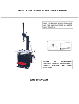
The Tyre-Changer must be transported in its original packaging
The packaged machine has to be moved by mean of a fork lift of suitable capacity (500 kg min.). Please, insert the forks
as shown by the following picture “g. 1”.
Remove the protective cardboard, remove all xing screw and free the Tyre-Changer from its original pallet.
Check the perfect condition of the machine, making sure that no part is damaged or missing, referring to the picture at
page 10.
If in doubt, please do not use the machine and get in touch with your Distributor for further steps.
Keep packing elements away from children.
All packing elements must be stored in the proper stocking areas.
Note: All the most delicate surfaces of the Tyre-Changer are coated by a special rust-proof oil.
Some oil traces may leak after coating procedure: please, remove them accordingly.
Lifting point
Gross weigth 455 Kg.
g. 1
g. 2
After tyre-Changer positioning, take of the lifting belt.
The machine must be moved by means of suitable capacity (fork-lift: 500 kg min. as per “g. 1” or crane with liftin-
gbelt: 500 kg min. as per “g. 2”).
Lifting point
After having positioned the machine, in its nal location,
release the safety pin against accidental tilting of the arm
(g. 3) Put the pin together with the other standard ac-
cessories delivered with the machine, for any future need.
Fig. 3

9
Place Tyre-Changer onto a levelled-out, smooth and not slippery oor with a suitable load capacity.
No bolt down installation is required. In case of bolt-down installation, please refer to all 4 holes on the base of the machine,
drilling through 100 mm into the oor and using suitable bolts for xing.
If the machine is installed outside it must be protected by a appropriate lean-to shed.
The electric network of the installation area must be provided with adequate earth plate and connected to an automatic
circuit-breaker (differential) set at 16 mA.
Should the Tyre-Changer be lacking in electric plug, the user must set one - at least 16 A and conform to the voltage of
the machine, in compliance with the regulations in force.
The pneumatic network of the installation area must be provided with min. 8 bar working
pressure outlet.
Connect the machine to the pneumatic network by means of the air tting on oiler lter/
regulator installed onto the rear section of the machine.
Fig. 4
When choosing the place of installation be sure that it complies with
current safety-at-work regulations.
The Tyre-Changer must be connected to the main electric power supply
and the compressed air system. It is therefore advisable to install
the machine near these power sources.
The installation area must leave at least the room shown in picture
“g. 4”, so as to allow all parts of the machine to operate correctly
and without any restriction.
1850

10
Roller bead
loosening unit
Pedal control units
Wheel positioning device
(optional)
cod. 9237720
Inating unit with pres-
sure gauge and pneu-
matic locking
Center plate
Roller bead loose-
ning control unit
Leverless mouinting/de-
mounting system QX
TubeLess inating
unit (optional)
cod. 9236665
Locking nut
Press Arm

11
-Tilting pole pedal control
-Clockwise and anticlockwise centre plate (ref. 15) rota-
tion pedal control
-Wheel positioning device control pedal (optional)
-Ination pedal control
-Bead loosening rollers override engaging button
-Bead loosener locking and override (ref. 5) activation
switch.
-Bead loosener releasing button.
-Bead loosener “forward” movement button
- Bead loosener “back” movement button
-Upper bead loosening roller lifting button
-Upper bead loosening roller lowering button
-Lower bead loosening roller lowering button
-Lower bead loosening roller lifting button
-Deation button (inating: by pedal 4)
-Center plate
-Upper bead loosener roller
-Press arm control switch
-Lower bead loosener roller
-Operating arm control button
-QX leverless system control switch
-Upper bead loosener tilting control
-Center plate pneumatic locking switch
Handle for disengagement of the Lever-Less mounting tool

12
Before starting demounting a tyre, it is of CRUCIAL IMPORTANCE to identify the measurements of the rim and of the
tyre, as well as to make sure that neither the rim nor the tyre are damaged.
Warning: these very important procedures have to be correctly performed to reduce risks of tyre
bursting while re-mounting and inating the tyre on the rim.
Each rim bears an indication of their diameter, width, number of humps etc.
A = 8 nominal width of the rim in inches (1 inch= 25.4 mm)
B = J size of the ange
C = 15 nominal diameter of the rim
D = H2 double hump (anti bead removing edge)
Each tyre bears a considerable amount of details, among which are the dimen-
sions, type and maximum speed.
Example:
A = 205 width of the tyre (the distance between tyre sides, expressed in
millimetres)
B = 65 ratio percentage between the height of the section and its width
C = R type of tyre (R= radial)
D = 15 keying diameter(diameter of wheel and rim) in inches
E = 91 index of the maximum load born by each wheel
F = H maximum admitted speed of the tyre (H= 210 Km/h)
G = TL type of tyre (T= Tubeless)
A D
B C
A
F
E
C
B
D
G
The picture on the right side symbolizes a rim as a clock face.
The valve positions described by the following working steps
always refer to the represented clock-face hours-marks.

13
A “standard wheel” is a car wheel with steel or alloy rim, with center hole, drop centre close to the external border of the
rim and a standard tyre (not RUN-FLAT nor LowProle).
Low prole tyres (UHP) are those in which the height (H) and the width (C) have a ratio lower than 0.5 (i.e. low prole
series 45 stands for a ratio of H/C = 0.45).
For tyres to be considered as low prole (UHP), they must also have a maximum speed code of equal to and/or higher
than V.
Q= to 160 km/h
R= to 170 km/h
S= to 180 km/h
T= to 190 km/h
RUN-FLAT tyres are those which allow to continue to drive the vehicle for a preset number of miles and at a preset
speed, even if they have no internal pressure. These parameters change from one manufacturer to another.
The market currently offers 2 different types of RUN-FLAT tyres:
- Those with reinforced sidewall (self-supporting) where, thanks to a different mix and a reinforced structure, the shoulder
of the tyre can bear the weight of the vehicle even when the internal pressure of the tyre is zero.
- Those with internal support which have a ring inside the rim that bears the sidewall of the tyre when there is no pressure
inside it. The internal support may be made of plastic (Pax-Sistem) or of metal (Support-Ring).
All the tyres which do not correspond to the above mentioned descriptions have to be considered as “standard tyres”.
This Tyre-Changer is able to handle all types of wheels with “standard” tyres, LowProle (UHP) and RUN-FLAT tyres
with reinforced side.
RUN-FLAT tyres with internal support (PAX System or Support-Ring type) mounting/demounting procedures need spe-
cial accessories to be used according precise dedicated instructions.
The mounting and demounting procedure is similar with “standard” tyre, LowProle tyre (UHP) tyre or RUN-FLAT tyre
with reinforced side (self-supporting).
The bead-breaking procedure should be operated by shovel-blade bead-breaker with “standard” wheels – in order to
save time – while the rollers bead-breaking unit has to be used for all LowProle (UHP) and RUN-FLAT tyres.
U= to 200 km/h
H= to 210 km/h
V= to 240 km/h
W= to 270 km/h
ZR= > 240 km/h
ZR(Y)= > 300 km/h
WDK is a German certied body charged with the evaluation of tyre-changers functioning and their capability to perform
good and safe operations on RUN-FLAT and UHP tyres correctly, to avoid permanent and potentially dangerous dama-
ges to tyres.
In order to perform a correct demounting and mounting process, the following premises are strictly compulsory:
1. Guidelines knowledge - WDK literature provides all necessary guidelines for all tyre brands and models, including all
theoretical and practical instructions to avoid any possible damage to tyre, rim and pressure sensor.
2. Certied tyre-changer - This Tyre-Changer is WDK certied and fulls all WDK requirements.
3. Qualied operator – The specic technical courses provide the operators with the necessary WDK guidelines and
service instructions. Dedicated WDK ofcial courses are available to get the WDK diploma, when necessary.

14
Before lifting and positioning the wheel onto the centre-plate, please:
- remove all weights from the rim by a proper tool carefully,
- remove any object or tool which could interfere with lifting.
-Put the wheel vertically onto the optional wheel positioning device (rim back facing the Tyre-Changer)
-Press the control pedal ref. 3 to lift the wheel-positioning device. Once the wheel is over the centre-plate, align the
wheel central hole to the centre-plate central hole.
-Release the control pedal fef. 3 to lower the wheel positioning device. Rotate the wheel in order to make one xing
hole of the rim match with the driving pin of the centre-plate.
Wheel positionig device
(optional)
Wheel positionig device
control pedal
Centre-plate
Driving pin

15
Insert the ring nut hub correctly (the cone plastic cover preserving the alloy rims from damages)
Turn the ring nut hub clockwise by hand until you nd the exact coupling position, then press the hub and
turn it clockwise by 90° to its full-stroke
Release the ring nut and make sure it raises by 0,40° (10 mm) approximately, otherwise turn it slightly
clockwise or counter-clockwise lifting up the hub.
Make sure the plastic cone is in contact with the rim, perfectly centred with the drop-centre hole, the split of
the nose matching up with the driving pin.
Tighten the ring nut so that it moves up to the cones and continue tightening so that the wheel is pushed
rmly on the ange of the spindle.
If the tyre-changer is provided with the optional pneumatic locking system:
Insert the ring nut hub correctly (the cone plastic cover preserving the alloy rims from damages).
Turn the ring nut clockwise by hand until the exact coupling position, press the ring nut until its end-stroke
and rotate the ring nut hub 90° by hand.
Release the ring nut and make sure thet it raises by 0,40° (10 mm) approximately.
Rotate the pneumatic locking switch onto the manometer panel to the locking position.

16
Check the correct centering and locking of the wheel onto the centre-plate.
Check that the upper disk arm is in the right position ()
-to move the upper disk in its right position: unlock it from rest position by pressing the right lever
to the left (), then lift the disk arm support by hand and lock it by pressing the right lever to the right ()
Turn the switch clockwise to free the bead-breaking unit and position it by handling the console, in order to let the
upper roller keep to 5 mm distance from the rim border, then lock the bead-breaking until by turning again te switch
clockwise.
Move the bead breaking arm onto the tyre by pressing buttons an
Step 1
-Remove all weights from the rim by a proper tool, paying attention not to damage the rim.
-Before starting any operation, please check the eventual presence of a pressure sensor. In positive case, it is prefe
rable to check its efciency by a dedicated diagnostic tool.
-The bead loosening rollers are mounted on special ttilting supports to ease bead loosening on wheels with high prole
or soft tyres. This procedure is “Over Run”
Make sure the tyre is completely before starting any operation on the wheel.
Pay attention to the valve sensor position during bead loosening steps.
Wrong movements of the upper roller could damage the sensor.
Lift up the hook lever
to release the lower
roller.
Push down the hook
lever to release the
upper roller
Avoid contacts between the lubricating paste and the valve
sensor, if any.

17
Fase 3
Keep the bead-loosening unit set up as for upper bead release: the lower roller is always aligned with the upper one,
at 5 mm distance from rim lower border already.
Lift the lower roller until it touches the lower bead using controls
for lifting and for lowering.
Start spinning the wheel anticlockwise by pressing pedal .
- While spinning the wheel, push the lower roller up over the edge of
the rim, then press and hold down the “over-stroke” function button 5
going on lifting the roller until the bead detaches from the rim.
- As soon as enough space is available, grease both inner surface of
the rim and tyre bead carefully with a proper tyre lubricating paste.
for a better control of the lower bead loosening
please refer to the dedicated mirror tted onto
the Tyre-Changer main frame.
- Once the bead gets loosened, raise and move away the upper roller
by acting on button 10.
Fase 2
- Spin the centre-plate until the valve reaches position
at “3 o’clock” position.
- Lower the bead loosening roller until it touches the tyre
using controls 9 for lowering and 8 for lifting.
- Start spinning clockwise pressing pedal 22.
Note: the centre-plate can spin at 2 different speeds, according to
operator’s preferences
- While spinning the wheel, push the bead loosening upper roller down
under the edge of the rim, then press and hold down the “over-stroke”
function button 5 going on lowering the roller until the bead detaches
from the rim.
- As soon as enough space is available, grease both inner surface
of the rim and tyre bead carefully with a proper tyre lubricating paste.

18
The lower bead of reverse drop centre rims with signicant width may be hard to break with the lower disk.
In this case it is possible to use the upper bead-breaking disk to break the lower bead of the tyre:
-tilt down the upper disk arm support to its lower position (step 1) to get both upper-and lower-bead loosening disks at
the same tilt-angle (step 2);
-follow instructions as per chapter “18 BEAD LOOSENING” at page 16.
Driving could be affected by vibrations caused by deformations of the rim and/or
of the tyre. To optimize the wheel-balancing, it is necessary to position the wheel
onto the Tyre-Changer again to bead-break and lubricate the rim and the tyre,
spinning the tyre around the rim to a proper position.
Both upper and lower rollers make this process easier, by gently holding the tyre
steady while the centre-plate spins the rim until the correct matching position.
Once the bead loosening process is completed, and the wheel is already positioned onto the center-plate, check and
ensure its locking and centering.
- Turn the wheel until the valve is in the “1 o’clock” position
(roughly 10 cm - 4” distance from the mounting tool) in order
to avoid possible damages to the valve or the pressure
sensor.
10 cm
Step 1
Upper bead loosening
arm
Lower bead loosening
arm
Step 2

19
Fig. 6
Fig. 5B
Fig. 5
-Press the pedal ref. to position the mounting arm close to the wheel while driving.
The mounting arm by handling (g. ), lock it in position 1 by ref. 19 (g. ) to lock the operating arm and the hori-
zontal arm at the same time.
Automatically the mounting tool is moved up and away from the rim border to have a
clearance of approx. 2 mm when locked
- Lower the lever ref. to insert the mounting tool between the bead and the rim edge. The mounting tool should pe-
netrate enough to hook the tyre bead to let the operator complete the tyre demounting: spin slowly the wheel until the
mounting tool is positioned correctly.
A gentle pressure on the tyre sidewall by the upper roller could help the mounting tool positioning.
- As soon as the bead is perfectly hooked, lift the mounting tool by raising lever ref. to pull out the bead.
To make the lifting easier set the tyre pressing unit at “6 o’clock” position and press the tyre side (g. 6).
Get a further help by contemporarily lifting the lower tyre side by the lower bead-loosening roller (g. 7).
Fig. 7
- In order to help the bead coming out and reduce the stress to the tyre:
insert the plastic lever (as shown by picture aside) and spin the wheel
clockwise while lifting the tyre by the lower bead-loosening roller.
The above mentioned action is compulsory for UHP and RUN-FLAT
tyres according to WDK rules.
- Press down on pedal ref. to rotate the wheel clockwise until the entire bead is lifted from the rim
rim and tyre must spin together as one.

20
- Before pulling out the lower bead, spin the wheel to let the valve
reach “1” or “2” o’clock position in order to avoid possible
damages to the valve and the sensor - if any.
- Lower the lever ref. to insert the demounting tool under the
lower bead. Raise the lever ref. to lift the demounting tool and
the bead.
- Raise the lower bead loosening roller to lift the tyre until the lower
bead is 1 cm over the upper rim edge.
- In order to help the above mentioned operation, lift the tyre
manually at “2” or “3” o’clock position and insert the plastic lever
as per WDK rules for UHP and RUN-FLAT tyres.
- Spin the wheel clockwise until the tyre complete coming out.
- Press the pedal ref. to move the mounting arm away, push the
rollers bead breaking unit away and pull out the tyre.
- Check the status of the pressure sensor - if any - and replace it if
necessary.
Once the manual demounting is nished, the standard position of the retractable claw can be restored by lowering the
handle ref. ..
Handle
Retractable claw
Fixed claw
Fig. 1 Fig. 2
The Tyre-Changer is provided with a patented system which allows the use of a
standard steel lever to demount special wheels as:
- Wheels with very narrow rims,
- Wheels with very tender tyre sidewalls,
- Motorcycle wheels
The above wheels can not easily - or not at all demounted with the standard
LeverLess system.
In order to demount a tyre manually by a standard lever:
- pull the retractable claw up away from working area by lifting the handle ref. ; up (g. 1).
- lean the manual lever onto the xed claw (g. 2).
/