Page is loading ...

MODEL 340
SEMITRAILER
OPERATOR’S MANUAL
1900 North Street
Marysville, KS 66508
(785)562-5381
F-374-1203 12/03


MODEL 340
SEMITRAILER
OPERATOR’S MANUAL
PURCHASED FROM: DATE / /
ADDRESS:
PHONE NO.: SERIAL NO.:
i

ii
REPORTING SAFETY DEFECTS
If you believe that your vehicle has a defect which could cause a crash or could
cause injury or death, you should immediately inform the National Highway Traffic
Safety Administration (NHTSA) in addition to notifying Landoll Manufacturing.
If NHTSA receives similar complaints, it may open an investigation, and if it
finds that a safety defect exists in a group of vehicles, it may order a recall and
remedy campaign. However, NHTSA cannot become involved in individual prob
-
lems between you, your dealer, or Landoll Manufacturing.
To contact NHTSA, you may either call the Auto Safety Hotline toll-free at 1-
800-424-9393 (or 366-0123 in Washington, D.C. area) or write to: NHTSA, U.S. De
-
partment of Transportation, Washington, D.C. 20590. You can also obtain other in
-
formation about motor vehicle safety from the Hotline.
In the event of a defect or problem with your LANDOLL equipment, please notify
LANDOLL CORPORATION:
LANDOLL CORPORATION
SALES AND SERVICE
1900 NORTH STREET
MARYSVILLE, KANSAS 66508
OR PHONE:
1-800-HAULOLL
(1-800-428-5655)
FAX NO.: (785)562-3240
FOR REPLACEMENT PARTS:
(785)562-4650
1-800-423-4320
FAX NO.: (785) 562-4654

iii
TABLE OF CONTENTS
SECTION NO. DESCRIPTION PAGE NO.
1 INTRODUCTION .......................................1-1
2 STANDARD SPECIFICATIONS.............................2-1
3 OPERATING INSTRUCTIONS..............................3-1
3-1 PRE-COUPLING OF SEMITRAILER AND TRACTOR ...........3-2
3-2 COUPLING OF THE TRACTOR TO THE SEMITRAILER .........3-2
3-3 CONNECTING TRACTOR SERVICES TO THE SEMITRAILER.....3-3
3-4 TRACTOR AND SEMITRAILER CHECK-OUT ..................3-3
3-5 TOWING THE SEMITRAILER .............................3-4
3-6 PARKING THE SEMITRAILER ............................3-5
3-7 UNCOUPLING TRACTOR FROM SEMITRAILER ..............3-5
3-8 TRAILER TILT LEVER ..................................3-6
3-9 AXLE CONTROL LEVER ................................3-6
3-10 GEARBOX CONTROLS .................................3-6
3-11 LOADING PROCEDURE ................................3-7
3-12 UNLOADING THE TRAILER.............................3-12
3-13 AUXILIARY HYDRAULIC POWER ENGINE OPERATION .......3-14
3-14 BULKHEADS........................................3-15
3-15 REAR IMPACT GUARD SYSTEM .........................3-15
3-16 ANTI-LOCK BRAKE SYSTEM (ABS) ......................3-17
3-17 COLD WEATHER OPERATION ..........................3-18
3-18 HOT WEATHER OPERATION ...........................3-18
4 MAINTENANCE AND LUBRICATION ........................4-1
4-1 MAINTENANCE SCHEDULE .............................4-1
4-2 MAINTENANCE PROCEDURES ...........................4-5
4-3 HITCH, FRAME, AND DECK .............................4-5
4-4 HYDRAULIC SYSTEM ..................................4-9
4-5 ELECTRICAL SYSTEM .................................4-9
4-6 SUSPENSION MAINTENANCE...........................4-10
4-7 ALIGNMENT ........................................4-11
4-8 BRAKE SYSTEM MAINTENANCE ........................4-14
4-9 HUB AND DRUM MAINTENANCE ........................4-19
4-10 WHEEL BEARING LUBRICATION AND ADJUSTMENT.........4-21
4-11 TIRE MAINTENANCE..................................4-22
4-12 GEARBOX MAINTENANCE .............................4-24
4-13 HYDRAULIC ENGINE PACKAGE .........................4-25
5 TROUBLESHOOTING GUIDE ..............................5-1

SAFETY PRECAUTIONS
THIS IS THE SAFETY ALERT SYMBOL. IT IS USED TO ALERT YOU
TO POTENTIAL INJURY HAZARDS. OBEY ALL SAFETY MESSAGES
THAT FOLLOW THIS SYMBOL TO AVOID POSSIBLE INJURY OR
DEATH.
DANGER DANGER INDICATES AN IMMINENTLY HAZARDOUS SITUA
-
TION WHICH, IF NOT AVOIDED, WILL RESULT IN DEATH OR
SERIOUS INJURY.
WARNING WARNING INDICATES A POTENTIALLY HAZARDOUS SITUA
-
TION WHICH, IF NOT AVOIDED, COULD RESULT IN DEATH OR
SERIOUS INJURY.
CAUTION CAUTION INDICATES A POTENTIALLY HAZARDOUS SITUA-
TION WHICH, IF NOT AVOIDED, MAY RESULT IN MINOR OR
MODERATE INJURY.
CAUTION CAUTION USED WITHOUT THE SAFETY ALERT SYMBOL INDI
-
CATES A POTENTIALLY HAZARDOUS SITUATION WHICH, IF
NOT AVOIDED, MAY RESULT IN PROPERTY DAMAGE.
iv

1INTRODUCTION
This manual provides operating, servicing, and maintenance instructions, with detailed parts lists for
Model 340 semitrailer, manufactured by Landoll Corporation, Marysville, Kansas 66508.
SECTION 1 gives basic instructions on the use of this manual.
SECTION 2 gives specifications for the semitrailer, including measurements and component
specifications. A Standard Bolt Torque Table is provided to give guidelines for
bolt torques to be used when servicing this product.
SECTION 3 gives instructions for the proper operation of the equipment.
SECTION 4 gives general maintenance procedures, a maintenance schedule, and a lubrication
schedule. Improper maintenance will void your warranty.
IF YOU HAVE ANY QUESTIONS CONTACT:
LANDOLL CORPORATION
1900 NORTH STREET
MARYSVILLE, KANSAS 66508
or phone:
(785) 562-5381 or
(800) 428-5655
or FAX:
(785) 562-4893
SECTION 5 is a troubleshooting guide to aid in diagnosing and solving problems with the
semitrailer.
PARTS LIST is a separate manual showing the various assemblies, subassemblies, and sys
-
tems. Refer to that manual when ordering Landoll replacement parts. Order parts
from your Landoll dealer.
WARRANTY The Warranty Registration form is located with the product documents. Fill it out
and mail it within 15 days of purchase. The Warranty is printed inside the front
cover.
NOTE: IMPROPER ASSEMBLY, MODIFICATION, OR MAINTENANCE OF YOUR
LANDOLL MACHINE CAN VOID YOUR WARRANTY.
COMMENTS Address comments or questions regarding this publication to:
LANDOLL CORPORATION
1900 NORTH STREET
MARYSVILLE, KANSAS 66508
ATTENTION: PUBLISHING -DEPT. 55
1-1


2STANDARD SPECIFICATIONS
CAPACITY*:
SINGLE AXLE .....................................11,800 LB. DISTR. - 10,000 LB. in 10 FT.
KING PIN SETTING: .............................................................18”
.....................................................................43"SETBACK
UNDERCARRIAGE TRAVEL: .....................................................10’-6"
STANDARD LOAD ANGLE: ........................................................12°
HYDRAULIC HOOKUP:
QUICK COUPLERS .................................... FLAT FACE 3/4" BODY SIZE
MAXIMUM OPERATING PRESSURE .......................................2500 PSI
OPERATING FLOW ....................................................17GPM
ELECTRICAL HOOKUP: ............................................7-WAY CONNECTOR
AIR HOOKUP: ............................................COLOR CODED GLAD HANDS
SPECIFIC BOLT TORQUES
AIR RIDE SUSPENSION:
EQUALIZER BEAM PIVOT AND ADAPTER BOLTS
DESIGNATED W/ NEWAY ON BOLT HEAD............................800FT.-LBS.
DESIGNATED W/ HOLLAND NEWAY ON BOLT HEAD ...................550FT.-LBS.
SHOCK ABSORBER MOUNTING ......................................150FT.-LBS.
AIR SPRING MOUNTING: 1/2" .........................................35FT.-LBS.
3/4" .........................................35FT.-LBS.
FOUR SPRING SUSPENSION:
AXLE CLAMP U-BOLTS ............................................ 300FT.-LBS.
EQUALIZER BEAM PIVOT BOLT ...................................480-500 FT.-LBS.
TORQUE ARM BOLT ...............................................250FT.-LBS.
TORQUE ARM CLAMP NUTS ..........................................60FT.-LBS.
WHEEL FASTENERS - ALL MODELS:
OUTER SPINDLE NUTS ..........................................250-400 FT.-LBS.
PILOT WHEEL NUTS ............................................450-500 FT.-LBS.
* CAPACITY RATINGS ARE FRAME CAPACITIES ONLY. ACTUAL LOAD CAPACITIES MAY BE RE
-
STRICTED BY FACTORS SUCH AS GROSS AXLE WEIGHT RATINGS (GAWR) OR STATE AND FED
-
ERAL REGULATIONS.
2-1

2-2
LANDOLL CORPORATION
GENERAL TORQUE SPECIFICATIONS (REV. 4/97)
THIS CHART PROVIDES TIGHTENING TORQUES FOR GENERAL PURPOSE APPLICATIONS WHEN SPECIAL TORQUES ARE NOT SPECIFIED
ON PROCESS OR DRAWING.
ASSEMBLY TORQUES APPLY TO PLATED NUTS AND CAPSCREWS ASSEMBLED WITHOUT SUPPLEMENTAL LUBRICATION (AS RECEIVED
CONDITION). THEY DO NOT APPLY IF SPECIAL GRAPHITE MOLY-DISULFIDE OR OTHER EXTREME PRESSURE LUBRICANTS ARE USED.
WHEN FASTENERS ARE DRY (SOLVENT CLEANED), ADD 33% TO AS RECEIVED CONDITION TORQUE.
BOLT HEAD IDENTIFICATION MARKS INDICATE GRADE AND MAY VARY FROM MANUFACTURER TO MANUFACTURER.
THICK NUTS MUST BE USED ON GRADE 8 CAPSCREWS.
USE VALUE IN [ ] IF USING PREVAILING TORQUE NUTS.
TORQUE IS SPECIFIED IN FOOT POUNDS
UNC
Size
SAE
Grade
2
SAE
Grade
5
SAE
Grade
8
UNF
Size
SAE
Grade
2
SAE
Grade
5
SAE
Grade
8
1/4-20 4 [5] 6 [7] 9 [11] 1/4-28 5 [6] 7 [9] 10 [12]
5/16-18 8 [10] 13 [16] 18 [22] 5/16-24 9 [11] 14 [17] 20 [25]
3/8-16 15 [19] 23 [29] 35 [43] 3/8-24 17 [21] 25 [31] 35 [44]
7/16-14 24 [30] 35 [43] 55 [62] 7/16-20 27 [34] 40 [50] 60 [75]
1/2-13 35 [43] 55 [62] 80 [100] 1/2-20 40 [50] 65 [81] 90 [112]
9/16-12 55 [62] 80 [100] 110 [137] 9/16-18 60 [75] 90 [112] 130 [162]
5/8-11 75 [94] 110 [137] 170 [212] 5/8-18 85 [106] 130 [162] 180 [225]
3/4-10 130 [162] 200 [250] 280 [350] 3/4-16 150 [188] 220 [275] 320 [400]
7/8-9 125 [156] 320 [400] 460 [575] 7/8-14 140 [175] 360 [450] 500 [625]
1-8 190 [237] 408 [506] 680 [850] 1-14 210 [263] 540 [675] 760 [950]
1-1/8-7 270 [337] 600 [750] 960 [1200] 1-1/8-12 300 [375] 660 [825] 1080 [1350]
1-1/4-7 380 [475] 840 [1050] 1426 [1782] 1-1/4-12 420 [525] 920 [1150] 1500 [1875]
1-3/8-6 490 [612] 110 [1375] 1780 [2225] 1-3/8-12 560 [700] 1260 [1575] 2010 [2512]
1/1-2-6 650 [812] 1460 [1825] 2360 [2950] 1/1-2-12 730 [912] 1640 [2050] 2660 [3325]
METRIC
COARSE THREAD METRIC CLASS 10.9 FASTENERS AND CLASS 10.0 NUTS AND THROUGH HARDENED FLAT WASHERS, PHOSPHATE
COATED, ROCKWELL “C” 38-45.
USE VALUE IN [ ] IF USING PREVAILING TORQUE NUTS.
Nominal
Thread
Diameter
mm
Standard Torque Nominal
Thread
Diameter
mm
Standard Torque
Newton-
Meters
Foot-
Pounds
Newton-
Meters
Foot-
Pounds
6 10 [14] 7 [10] 20 385 [450] 290 [335]
7 16 [22] 12 [16] 24 670 [775] 500 [625]
8 23 [32] 17 [24] 27 980 [1105] 730 [825]
10 46 [60] 34 [47] 30 1330 [1470] 990 [1090]
12 80 [101] 60 [75] 33 1790 [1950] 1340 [1450]
14 125 [155] 90 [115] 36 2325 [2515] 1730 [1870]
16 200 [240] 150 [180] 39 3010 [3210] 2240 [2380]
18 275 [330] 205 [245]
Table 2-1 General Torque Specifications

2-3
LANDOLL CORPORATION
HYDRAULIC FITTING TORQUE SPECIFICATIONS
37
o
JIC, ORS, & ORB (REV. 10/97)
THIS CHART PROVIDES TIGHTENING TORQUES FOR HYDRAULIC FITTING APPLICATIONS WHEN SPECIAL TORQUES ARE NOT SPECIFIED
ON PROCESS OR DRAWING.
ASSEMBLY TORQUES APPLY TO PLATED CARBON STEEL AND STAINLESS STEEL FITTINGS ASSEMBLED WITHOUT SUPPLEMENTAL
LUBRICATION (AS RECEIVED CONDITION). THEY DO NOT APPLY IF SPECIAL GRAPHITE MOLY-DISULFIDE OR OTHER EXTREME PRESSURE
LUBRICANTS ARE USED.
BRASS FITTINGS AND ADAPTERS - 65% OF THE TORQUE VALUE FOR STEEL. STAINLESS STEEL, ALUMINUM AND MONEL - THREADS ARE
TO BE LUBRICATED
.
TORQUE IS SPECIFIED IN FOOT POUNDS
PARKER BRAND FITTINGS
Dash
Size
37 Degree
JIC
O-Ring
(ORS)
O-Ring Boss
(ORB)
-4 11-13 15-17 13-15
-5 14-16 — 21-23
-6 20-22 34-36 25-29
-8 43-47 58-62 40-44
-10 55-65 100-110 57.5-62.5
-12 80-90 134-146 75-85
-16 115-125 202-218 109-121
-20 160-180 248-272 213-237
-24 185-215 303-327 238-262
-32 250-290 — 310-340
LANDOLL CORPORATION
HYDRAULIC FITTING TORQUE SPECIFICATIONS
37
o
JIC, ORS & ORB (REV. 10/97)
THIS CHART PROVIDES TIGHTENING TORQUES FOR HYDRAULIC FITTING APPLICATIONS WHEN SPECIAL TORQUES ARE NOT SPECIFIED
ON PROCESS OR DRAWING.
ASSEMBLY TORQUES APPLY TO PLATED CARBON STEEL AND STAINLESS STEEL FITTINGS ASSEMBLED WITHOUT SUPPLEMENTAL
LUBRICATION (AS RECEIVED CONDITION). THEY DO NOT APPLY IF SPECIAL GRAPHITE MOLY-DISULFIDE OR OTHER EXTREME PRESSURE
LUBRICANTS ARE USED.
BRASS FITTINGS AND ADAPTERS - 65% OF THE TORQUE VALUE FOR STEEL.
TORQUE IS SPECIFIED IN FOOT POUNDS.
AEROQUIP BRAND FITTINGS
Dash
Size
37 Degree
JIC
O-Ring
(ORS)
O-Ring Boss
(ORB)
-4 11-12 10-12 14-16
-5 15-16 — 18-20
-6 18-20 18-20 24-26
-8 38-42 32-35 50-60
-10 57-62 46-50 72-80
-12 79-87 65-70 125-135
-14 — — 160-180
-16 108-113 92-100 200-220
-20 127-133 125-140 210-280
-24 158-167 150-165 270-360
-32 245-258 — —
Table 2-2 Hydraulic Fitting Torque Specifications


3OPERATING INSTRUCTIONS
This section supplies information for operation
of the trailer. It describes and locates controls and
gives general operation procedures. Read all in
-
structions, warnings, cautions and danger notes
before attempting to operate the trailer. Operators
must have proper training before operating the
semitrailer.
A hydraulic pump must be coupled to the
trailer hydraulic system, or the optional hydraulic
engine package started, before using hydraulic
controls.
WARNING
DO NOT OPERATE THE SEMITRAILER
WITH ANY KNOWN FAULT THAT
MIGHT ENDANGER THE OCCUPANTS,
NEARBY WORKERS, OTHER TRAFFIC,
THE LOAD, OR THE EQUIPMENT.
WARNING
DO NOT OPERATE THE SEMITRAILER
UNTIL YOU HAVE READ THE OPERA-
TOR’S MANUAL AND COMPLETELY
UNDERSTAND THE PROPER USE AND
FUNCTION OF ALL CONTROLS. IM-
PROPER USE CAN CAUSE PERSONAL
INJURY, DAMAGE TO YOUR SEMI-
TRAILER AND CARGO, AND CAUSE
TIME-CONSUMING BREAKDOWNS.
3-0.1
Air Brake System
The air brake system of the trailer is operated
from the towing vehicle after coupling. The towing
vehicle’s air system must be coupled to the trailer
and charged to 90 psi minimum before the brakes
can adequately function.
3-0.2
Anti-Lock Brake System (ABS)
The Anti-Lock Brake System of the semitrailer
is constantly powered by the auxiliary (blue) circuit
of the seven way electrical connector, with backup
power from the stop lamp (red) circuit, and ground
through the white wire. It is necessary that the blue
circuit is hot when the tractor key switch is on. The
blue circuit on the trailer may also not be used to
power any additional auxiliary devices while the
semitrailer is moving forward. If a fault exists in the
ABS, normal braking will occur, but the wheels
may lock. Service the ABS as soon as possible.
CAUTION
THE AUXILIARY (BLUE) CIRCUIT IS
FOR POWERING THE SEMITRAILER
ABS. THIS CIRCUIT MUST BE HOT
WHEN THE TRACTOR KEY SWITCH IS
ON. NO OTHER ELECTRICAL DEVICES
MAY BE POWERED BY THIS CIRCUIT
WHILE THE SEMITRAILER IS MOVING
FORWARD.
CAUTION
IF A FAULT EXISTS IN THE SEMI
-
TRAILER ABS, NORMAL BRAKING
WILL OCCUR, BUT WHEELS MAY
LOCK. SERVICE THE ABS AS SOON
AS POSSIBLE.
3-1

3-1 PRE-COUPLING OF SEMITRAILER AND TRACTOR
3-1.1 Slowly back the tractor up to the front
end of the semitrailer so the kingpin of the
semitrailer is centered between the tractor
fifth wheel jaws. Stop the tractor several
inches ahead of the semitrailer. Set tractor
parking brake.
3-1.2 The king pin plate should be the same
height as, or slightly lower than, the latch
area of the fifth wheel plate of the tractor. If
necessary, connect the tractor hydraulic lines
or start the trailer hydraulic power engine.
Use the TRAILER TILT (5TH WHEEL) lever
(See Figure 3-2) to raise or lower the king
-
pin plate sufficiently to allow proper coupling.
Drain all air and moisture from the tractor air
brake system in accordance with the tractor
manufacturer’s instructions.
3-1.3 Connect the service and emergency air
hoses of the tractor to their respective glad
-
hand on the front of the semitrailer. The trac
-
tor’s air hose couplings are then attached
and locked to the appropriate gladhands; the
red emergency line to the gladhand with
the “EMERGENCY” tag, and the blue serv
-
ice line to the gladhand with the “SERV
-
ICE” tag (See Figure 3-1). Chock the semi
-
trailer wheels before activating the semitrailer
air supply valve in the tractor. Set the semi
-
trailer brakes.
3-1.4 Check the air brake operations of the
semitrailer as follows:
a. Apply brakes and inspect brake action on all
wheels for prompt application.
b. Release brakes. All brakes should release
immediately. Air pressure should discharge
quickly from the relay emergency valve.
c. Disconnect the emergency air line from the
semitrailer gladhand. Semitrailer brakes
should promptly set.
d. Re-connect the emergency air line to the
semitrailer and activate the semitrailer air
supply valve. The semitrailer brakes should
set.
3-2 COUPLING OF THE TRACTOR TO THE SEMITRAILER
DANGER
KEEP ALL PERSONNEL CLEAR OF
FRONT, REAR, AND SIDES OF TRAC
-
TOR AND SEMITRAILER DURING COU
-
PLING, COMPONENT OPERATIONS,
AND UNCOUPLING. FAILURE TO STAY
CLEAR CAN RESULT IN SERIOUS
PERSONAL INJURY OR DEATH.
3-2.1 Verify the semitrailer wheels are
chocked and brakes function properly.
3-2.2 Make sure the tractor’s fifth wheel cou
-
pler is open.
3-2.3 Slowly back the tractor so its fifth wheel
contacts the front of the kingpin plate on the
semitrailer and slips under it. Continue back
-
ing until the fifth wheel coupler locks onto the
semitrailer kingpin.
3-2.4 Try to pull the tractor forward a few
inches to verify the vehicle coupling is se
-
cure. If the tractor disconnects from the
semitrailer: locate the source of the coupling
failure; repair before continuing; and repeat
Steps 3-2.3 and 3-2.4.
CAUTION
PUSHING SEMITRAILER BACKWARDS
CAN DAMAGE LANDING GEAR.
3-2.5 Check that the tractor couples securely
to the semitrailer before setting tractor and
semitrailer parking brakes.
IMPORTANT
KEEP BRAKES ENGAGED FOR REMAINDER
OF COUPLING, CHECK-OUT, AND PARKING.
3-2

3-3 CONNECTING TRACTOR SERVICES TO THE SEMITRAILER
3-3.1 Connect the tractor 7-way electrical plug
to the electrical receptacle on the front of the
semitrailer (See Figure 3-1).
IMPORTANT
THE KEY ON THE PLUG AND THE KEYWAY IN
THE SOCKET MUST BE PROPERLY ALIGNED
BEFORE INSERTING THE PLUG INTO THE
SEMITRAILER SOCKET.
3-3.2 If you have not already done so, con
-
nect the tractor hydraulic lines to the semi
-
trailer, unless your semitrailer is equipped
with the auxiliary hydraulic power engine
package.
IMPORTANT
SOME OIL MAY NEED TO BE REMOVED FROM
THE TRACTOR RESERVOIR TO ALLOW ROOM
FOR 7 GALLONS OF ADDITIONAL OIL DIS-
PLACED FROM THE SEMITRAILER HYDRAULIC
SYSTEM.
3-4 TRACTOR AND SEMITRAILER CHECK-OUT
3-4.1 While hydraulic power is operating, raise
the front end of the semitrailer with the
TRAILER TILT (5TH WHEEL) lever (See
Figure 3-2) until weight is off the landing
gear. Raise landing gear. Secure each leg
with a park stand retaining pin in fully re
-
tracted position before transporting.
WARNING
LANDING GEAR LEGS MUST BE
FULLY RETRACTED AND SECURED
WITH PINS BEFORE OPERATING OR
MOVING SEMITRAILER.
3-4.2
Lower the front end with the TRAILER
TILT (5TH WHEEL) lever until the semitrailer
is fully lowered. Hold lever in the down posi
-
tion until hydraulic system works against the
bottomed out hydraulic tilt cylinders.
3-4.3 Verify that the traveling undercarriage is
completely slid back to transport position.
Shut off hydraulic power.
3-3
HYDRAULIC
RETURN
SERVICE
AIR
HOOKUP
HOOKUP
ELECTRICAL
HOOKUP
HYDRAULIC
PRESSURE HOOKUP
EMERGENCY
AIR HOOKUP
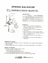
service hookups
Figure 3-1 Service Hookups (Front View)
Figure 3-2 Hydraulic Control Levers

3-4.4 Check the operation of all lights and sig
-
nals on the semitrailer for proper response to
switch positions (stop, right turn, left turn and
clearance).
3-4.5 Check that tire inflation matches the
pressure listed on the tire.
3-4.6 Check tractor/semitrailer combination for
air leaks. If air leakage is found, repair the de
-
fect before transporting.
3-4.7 Check that the oil in each hub is at the
proper level and free from contamination. If
hubs contain water, dirt, or other foreign mat
-
ter, clean them before transporting.
3-4.8 Check tractor air pressure. Pressure
must not fall below 65 psi, even after activat
-
ing brakes a couple of times. Set parking
brake and carefully remove all wheel chocks.
Set emergency brake and try pulling forward.
The semitrailer wheels must not rotate. If
semitrailer brakes do not apply, do not trans
-
port until defect, or defects, are repaired.
3-5 TOWING THE SEMITRAILER
3-5.1 Driving the tractor with the semitrailer
coupled behind requires constant attention to
the overall length. Turning, passing, acceler
-
ating, braking, stopping, and back-up require
special considerations. When executing
steep grades or turning tight curves, the
semitrailer must not be allowed to push the
tractor, or jackknifing may result. Application
of the semitrailer brakes to keep the semi-
trailer in tow will help prevent this situation.
To assure control, brake before descending a
hill or attempting a curve.
3-5.2 Make a moving test of the semitrailer
brakes at low and medium speeds before
traveling at highway speed.
a. The Anti-Lock Brake System (ABS) warning
lamp mounted at left rear side of the trailer
should come on when power is supplied to
the ABS by turning the tractor keyswitch on.
The warning lamp should go off once the
trailer exceeds 4 mph. If the warning lamp
does not go off, a fault exists in the trailer
ABS. Once the vehicle speed exceeds 4 mph,
the light should remain off unless a fault oc
-
curs or the keyswitch is turned off, then on
again.
3-5.3 Monitor the air pressure gauge on the
dash of the tractor. Pressure should not fall
below 90 psi at any time.
CAUTION
WHEN OPERATING TRAILER, DO NOT
BACK OVER CURB. THIS WILL CAUSE
SEVERE DAMAGE TO UNDERCAR-
RIAGE AND UNDERCARRIAGE CYLIN-
DER.
3-5.4 The semitrailer wheels track to the in-
side of the tractor during turns. Thus, turning
corners requires a wide swing to prevent
“curb hopping”, and to allow the semitrailer
wheels to clear any obstacle on the inside of
the corner.
3-5.5 To stop, use a gradual and smooth appli
-
cation of brakes. If grabbing occurs, apply less
pressure. Grabbing brakes are not efficient.
DANGER
ALWAYS CHECK BEHIND AND UNDER
THE TRACTOR AND SEMITRAILER
FOR PERSONS OR OBJECTS BEFORE
MOVING. FAILURE TO CHECK CAN
LEAD TO SERIOUS PERSONAL IN
-
JURY, DEATH, OR DAMAGE TO PROP
-
ERTY.
3-5.6 Backing should be done with care. Tail
overhang, semitrailer length, and allowable
space must be taken into consideration.
3-4

3-6 PARKING THE SEMITRAILER
3-6.1 Position tractor/trailer rig on a level,
solid surface.
3-6.2
Set the PARKING BRAKE, not the
semitrailer emergency hand brake, and
check for proper brake holding.
3-6.3 Chock wheels.
3-6.4 Check for any air leaks in lines, relay
valve, brake pods, or any other air system
component.
WARNING
WHEN LEAVING THE SEMITRAILER
UNATTENDED, POSITION ALL HY
-
DRAULIC CONTROLS TO THE NEU
-
TRAL OR “OFF” POSITION AND SHUT
OFF THE HYDRAULIC ENGINE POWER
SUPPLY, OR DISCONNECT THE TRAC
-
TOR HYDRAULIC HOOK-UP.
3-7
UNCOUPLING TRACTOR FROM SEMITRAILER
3-7.1 Park the semitrailer according to instruc
-
tions in Section 3-6.
3-7.2 Remove retaining pin and lower landing
gear to the ground. Hydraulically raise the
front end of the semitrailer until the next hole
in the landing gear is available. Insert pin
through both inner and outer legs of the
landing gear. Hydraulically lower semitrailer
onto the legs.
WARNING
SECURE EACH LEG WITH PIN BEFORE
LEAVING SEMITRAILER UNAT-
TENDED.
3-7.3 Pull the tractor fifth wheel plate latch re
-
lease.
3-7.4 Disconnect emergency and service air
lines and attach them to the tractor gladhand
holders.
3-7.5 Disconnect the 7-way cable and hydrau-
lic lines from the semitrailer and store with
the tractor.
3-7.6 Attempt to pull the tractor forward. If the
tractor uncouples, verify that all service lines
are disconnected and semitrailer wheels are
chocked. If tractor does not disconnect, re-
peat Sections 3-7.5 and 3-7.6.
3-7.7 Pull the tractor away from the semi-
trailer.
3-5

3-8 TRAILER TILT (5TH WHEEL) LEVER
The TRAILER TILT (5TH WHEEL) lever is lo
-
cated on the driver’s side of the semitrailer under
the outer frame beam. (See Figure 3-2) It has
three positions:
UP In this position, the front end of the
semitrailer rises to the load position.
CENTER This is the neutral position. The
semitrailer stays in its current posi
-
tion.
DOWN In this position, the front end of the
semitrailer lowers to the transport
position.
3-9 AXLE CONTROL LEVER
The AXLE CONTROL lever (See Figure 3-2)
is the control on the rear with three positions:
UP In this position, the undercarriage
slides forward for loading.
CENTER This is the neutral position.
DOWN In this position, the undercarriage
slides to the rear. The undercarriage
must be in the rear-most position for
transport.
3-10 GEARBOX CONTROLS
DANGER
1. THE GEARBOX IS NOT DESIGNED
OR INTENDED TO BE USED FOR LIFT-
ING OR MOVING PEOPLE. USING IT
THIS WAY CAN CAUSE SERIOUS IN
-
JURY OR DEATH.
2. NEVER ATTEMPT TO DISCONNECT
THE GEARBOX CHAIN CONNECTOR
WHEN THE CHAIN IS UNDER TENSION.
LOSS OF LOAD CONTROL, PROPERTY
DAMAGE, INJURY OR DEATH CAN RE
-
SULT.
3-10.1
The HYDRAULIC GEARBOX (WINCH)
CONTROL lever (See Figure 3-2) is the
center lever. It is a three position control:
UP In this position, the chain rotates
counter clockwise.
CENTER This is neutral position.
DOWN In this position, the chain rotates
clockwise.
3-6

3-11 LOADING PROCEDURE
3-11.1 Practice all standard industrial safety
standards (See Figure 3-4). Do not load any
payload that will overload any component of
the semitrailer or cause any unsafe condi
-
tion.
3-11.2 Proper operation requires that the un
-
dercarriage be pulled fully forward to create
lowest low load angle.
3-11.3 Park the tractor/semitrailer in a straight
line on level even surface. Set the tractor
brakes and release the semitrailer brakes
(See Figure 3-4).
3-11.4 Start operation of hydraulic power sys
-
tem. If the hydraulic engine package is in
-
stalled, start and warm up engine following
engine operating instructions in Section
3-13. (Read engine operator’s manual.)
3-11.5 Alternate between moving the undercar
-
riage forward and tilting the front of the bed
up until the undercarriage is fully forward and
the approach plate is on the ground. The
weight of the semitrailer bed should rest
partly on approach plate and partly on under-
carriage. The object is to have the approach
plate resting on the ground whenever the
center of gravity of the semitrailer and load is
behind the rear axle of semitrailer. In loading
position, the approach plate should be rest-
ing on the ground and the undercarriage fully
forward.
CAUTION
DO NOT ALLOW THE BACK SEMI
-
TRAILER AXLE TO LEAVE THE
GROUND. THIS CAN RESULT IN DAM
-
AGE TO THE SEMITRAILER.
WARNING
IN LOADING OR UNLOADING POSI
-
TION, THE APPROACH PLATE
SHOULD BE RESTING ON THE
GROUND AND THE UNDERCARRIAGE
FULLY FORWARD.
WARNING
ALWAYS USE LOW LOAD ANGLE TO
LOAD AND UNLOAD POWERED
PRODUCTS.
IMPORTANT
SECTIONS 3-11.6 THRU 3-11.12 DESCRIBE
GENERAL LOADING PROCEDURES FOR THE
SEMITRAILER. SECTIONS AFTER 3-11.12 ARE
MORE SPECIFIC OPERATION PROCEDURES
FOR LOADING CONTAINERS.
3-11.6 Winch or drive the load onto the semi-
trailer. Insure that the load is steering
straight up onto the semitrailer and does not
maneuver off the side of the semitrailer. Con-
tinue until load center of gravity is just ahead
of the axles. The load should never place
more weight on the kingpin than on the rear
axles during loading and unloading.
CAUTION
MAXIMUM CONCENTRATED LOAD IS
10,000 LBS. IN A 10 FT. AREA FOR A
SINGLE AXLE SEMITRAILER.
WARNING
1. THE SEMITRAILER MUST BE COU
-
PLED TO A TRACTOR AND THE LAND
-
ING GEAR RAISED OFF THE GROUND
BEFORE OPERATING.
2. DO NOT EXCEED THE GROSS AXLE
WEIGHT RATINGS FOR ANY AXLE ON
YOUR VEHICLE. THE COMBINED
WEIGHT OF THE SEMITRAILER AND
CARGO MUST NOT EXCEED THE
GROSS VEHICLE WEIGHT RATING
(GVWR) OF THE TRAILER.
3-7

WARNING
THE CENTER OF GRAVITY OF THE
LOAD MUST BE IN FRONT OF THE
CENTER OF THE UNDERCARRIAGE
WHENEVER THE APPROACH PLATE
IS NOT SUPPORTED BY THE GROUND.
FAILURE TO DO THIS CAN CAUSE THE
SEMITRAILER TO TILT BACK RESULT-
ING IN INJURY OR DEATH.
3-11.7 If the load center of gravity is not ahead
of the rear axle, alternate between tilting the
front of the bed up and moving the undercar-
riage to the rear, until the center of gravity of
the semitrailer load is in front of the rear
axle. Keep part of the load on the wheels
and part on the approach plate. Never move
the undercarriage so far to the rear that the
approach plate is lifted off the ground during
this procedure.
3-11.8 When the center of gravity of the semi
-
trailer and load is in front of the rear axle,
fully lower the tilt angle.
3-11.9 After bed tilt angle is fully lowered,
move the undercarriage to the rear until it is
in transport position. Hold TRAILER TILT
(5TH WHEEL) lever in the down position un
-
til hydraulic system works against the bot
-
tomed out Hydraulic Tilt Cylinders. Hold
AXLE CONTROL lever in the transport posi
-
tion until hydraulic system works against the
fully extended hydraulic axle cylinder.
3-11.10 If necessary, unsecure the load, move
load slightly forward or rearward on the load
bed to get correct weight distribution on king
-
pin and the semitrailer axles, and resecure
the load with the tiedowns and winch cable.
3-11.11 Shut down the auxiliary hydraulic
power engine following operating instructions
in Section 3-13.
3-11.12 Recheck that the load is properly se
-
cured. Assure maintenance schedule is up-
to-date and semitrailer is ready to be pulled.
3-11.13 The gearbox operates a chain drive
that makes a continuous loop from front of
trailer to the rear of trailer. The gearbox can
move the chain either clockwise or counter-
clockwise. The chain closest to the center of
the trailer is used to pull or push the con-
tainer on or off.
3-11.14 The pullouts are used to guide the
container onto the trailer. Position in for 96”
wide container and use the outer position for
102” wide container (See Figure 3-3).
IMPORTANT
SECTIONS 3-11.15 and 3-11.16 are same for
loading all containers.
3-11.15 Check the container to be loaded to
see if the container front corner castings are
an inch or so off the ground. If they are not,
the container will have to be lifted first and
blocks placed a few inches behind front of
container to keep container an inch or so off
the ground (See Figure 3-4).
a. The trailer can be used to lift empty contain
-
ers. The trailer should be straight in front of
container and as close to container as possi
-
ble without hitting container.
b. Operating trailer using the same methods
described earlier in this section, move the un
-
dercarriage forward a couple feet and tilt the
front of trailer up fully.
3-8
Figure 3-3 Pullout Location
Figure 3-4 Front Corner Castings
/