Thermocet Transparente 120 Owner's manual
- Category
- Fireplaces
- Type
- Owner's manual
This manual is also suitable for

Page.1
OPERATING AND INSTALLATION INSTRUCTIONS
Gas-fired hearth:
TRANSPARENTE 73-100-120-140-160
GREAT BRITTAN-GB IRELAND-IE

Page.2
1. GENERAL Page 3
Note
Warning
Maintenance
Package contents
2. APPLIANCE SAFETY Page 4
2.1 Safety
3. FIRING THE FIRST TIME Page 5
4. REMOTE CONTROL Page 6
4.1 General
4.2 Hand-held transmitter
4.3 Screen setup
4.4 Time setup
4.5 Controls (Remote Control)
4.6 Possible error messages
4.7 Adjusting the flame size / Extinguishing the fire
4.8 Switching the unit off.
4.9 Inserting and replacing the batteries
5. MANUAL OPERATION Page 9
4.1 Igniting the fire
4.2 Extinguishing the fire
4.3 Switching the unit off
6. INSTRUCTIONS FOR THE MERTIK MAXITROL GV60 EN REMOTE CONTROL Page 10
7. TECHNICAL DETAILS, GV60 Page 12
8. MERTIK GV60 TOUBLESHOOTING FOW CHART Page 14
9. OPERATING INSTRUCTIONS FOR THE DUNGS GAS REGULATOR UNIT AB Page 17
9.1 General
9.2 Infra-red remote control and its operation
9.3 Igniting the gas fire.
9.4 Basic system construction
9.5 Connection to the gas regulation block wiring
9.6 Adjusting the gas regulation unit
9.7 Connecting to the mains supply
9.8 Chimney
10. CONNECTING THE ELECTRICAL AND GAS SUPPLIES Page 18
10.1 Electrical connection.
10.2 Order of installation: electrical connections.
10.3 Optional protected air supply and combustion gas flue system for type II gas-fired block
fires in naturally and mechanically ventilated homes.
10.4 Gas connection
11. GAS SUPPLY DETAILS Page 23
12. MAINTENANCE CHECKLIST Page 24
13. MAINTENANCE FAULT CHECKLIST, MERTIK MAXITROL GV60 Page 26
14. INSTALLATION INSTRUCTIONS FOR THE TRANSPARENTE Page 26
14.1 Installing the unit
14.2 Deflector plates
14.3 Chimney
14.4 Warning
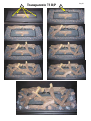
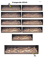
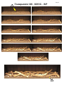
15. INSTALLING THE CERAMIC WOOD SETS FOR THE TRANSPARENTE 73-100-120-140-160 Page 27
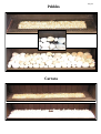
16. INSTALLING THE PEBBLE SET Page 27
17. INSTALLING THE CARRARA STONE SET Page 27
ILLUSTRATIONS Pages 28 to 34
ALL RIGHTS RESERVED.
(2/15042012)

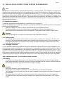
Page.3
We hope that you enjoy the warmth of your new Transparente. Read these instructions carefully before
installing and using the Transparente. Keep these instructions in a safe place. Always provide the follow-
ing information if the Transparente breaks down: model and serial number, which can be found on the
unit. Your receipt of purchase is your proof of warranty.
1. GENERAL
Check the unit immediately after delivery to confirm that it has not been damaged during transport. If it is dam-
aged in any way, please inform your supplier immediately and provide as many details as possible. Your Trans-
parente has been coated with heat-resistant enamel that can withstand extremely high temperatures. Allow the
Transparente to burn at the highest setting and ventilate the room thoroughly during the first hours of use. As
the enamel is cured, convection will cause a non-hazardous smell and/or some smoke to be emitted.
Attention
The Transparente must be installed, connected and checked by a qualified fitter in accordance with national,
regional, and local standards and regulations. The fitter should verify that the Transparente is gas tight for gas
and combustion products and that the various components and functions are operating correctly. The fitter
should furthermore ensure that the identification plate is placed in a prominent position in the immediate vicinity
of the burner. The flue system also needs to comply with the applicable regulations.
Warning
The Transparente will become hot during use. Therefore you should take care, for example, by keeping chil-
dren and those requiring help away from the immediate vicinity of burning fires. Furthermore, the Transpar-
ente should not be placed on or against flammable materials (curtains, etc.).
PACKAGE CONTENTS
TRANSPARENTE 73-100-120-140-160 AB
Complete appliance
Operating and installation Instructions
Decoration set:
Ceramic block set - Transparente 73-100-120-140-160 AB.
Pebble set - Transparente 73-100-120-140-160 AB.
Carrara set- Transparente 73-100-120-140-160 AB.
Optional:
Support iron

Page.4
2. SAFETY DEVICE
The unit is fully safeguarded by means of thermo-electric pilot light protection to prevent unforeseen discharge
of gas from the main burner.
2.1 Safety
Do not place ceramic burner decoration material or logs against the pilot burner. Ensure the pilot light is able to
burn freely over the main burner. Good ignition of the main burner is only guaranteed if this is the case. Not ad-
hering to these instructions can lead to dangerous situations.
The unit, complete concentric flue system and flue terminal need to be cleaned and checked annually by a
recognised gas technician/fitter, so the unit continues to operate safely. For additional instructions, see
Chapter 10: Maintenance.
If, for whatever reason, the pilot light extinguishes, you must wait 5 minutes before igniting the pilot light
again.
The unit may not be operated without the glass panel being in place.
It is not permitted to place flammable materials on the ceramic wood inset.
The layout of the main burner with ceramic burner decoration material and wood inset may under no cir-
cumstances be changed or added to.
Light flammable materials, such as nylon clothing or flammable liquids, may not be placed near the unit.
Ensure children and other persons unaware of the operation of a gas unit, are supervised at all times when
near the unit.
Use a fireguard to protect against burns and protection of the children and persons named above.

Page.5
3. FIRING THE FIRST TIME
The device is provided with a heat-resistant lacquer which is resistant to very high temperatures. During the first
hours there may be a more or less unpleasant smell caused by the burning of the paint, this is not dangerous. To do
this as quickly as possible, firing the device for several hours to burn and the room well ventilated.
3.1 Daily maintenance
* Avoid having a lot of dust and smoke particles from cigarettes, candles and oil lamps in the air of your home.
Heating of these particles by the convection system of the unit, can lead to discoloration of walls and ceilings.
Regularly remove any dust deposits with a vacuum cleaner.
* If the device is spilled, it should be stopped immediately. Only when the device has cooled sufficiently before
cleaning. Never use an abrasive, aggressive cleaning agents or fireplace cleaner, only a dry, lint-free cloth.
* By several dealers are also heat resistant spray paint available mountable, so that the annual maintenance for
small stains or areas of damage.
3.2 Important tips for heating with gas or wood burning stoves and fireplaces.
Prevent discoloration of walls and ceilings!
In any room there are always particles in the air as it is regularly vacuumed! These particles are clearly visible
in rays of sunlight. As long as the concentration of particles in the air remains, you will not suffer this experi-
ence. Only when these particles by any cause whatsoever in larger quantities through the room and particularly
if the extra air is polluted by soot and tar particles, caused by eg the burning of candles or oil lamps and smok
ing cigarettes or cigars, one can speak of a poor indoor climate! In a heated living space cooled air flows
slowly across the floor to the heater. In this air is always dust and other polluting particles that will leave de
posits on cold and often damp surfaces. Especially in a not yet dry construction (construction moisture) this
problem may arise. An undesirable outcome of such re-phenomenon could be discoloration of walls or ceil-
ings!
How can you prevent these problems?
* With a new build chimney or after rebuild to wait at least 6 weeks before going firing.
* The construction moisture must have disappeared from walls, floors and ceilings.
* The room where the unit is located should be well ventilated.
* The required air ventilation must be taken in accordance with local regulations.
* Make minimal use of candles and oil lamps and keep the taper as short as possible.
* These two "atmospherics" provide considerable quantities of polluting and unhealthy soot in your home.
* Cigarette and cigar smoke contains tar, which on heating on cold and damp walls will precipitate.
* When a poor internal climate phenomenon, although to a lesser extent, also above radiators and light fittings
and ventilation may occur.

Page.6
4. REMOTE CONTROL
Please note:
Before the device is switched on, the air supply flue gas discharge valve must be opened.
The control knob is located front-right in the unit. If this valve is not open, the unit will not function
4.1 General
* The unit is operated using a radio-controlled remote control. This consists of a manual transmitter and a re-
ceiver. The receiver is connected to the gas control block.
* The receiver and the gas control block are located in the operating box.
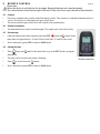
4.2 Manual transmitter
* The transmitter uses a radio-controlled signal. The signal code is set at the factory
4.3 Screen setup
* After the batteries have been inserted, press the OFF button and (small) at the
same time to toggle between °F (and 12 hour clock) and °C (and 24 hour clock).
* Wait a moment or press OFF to return to MAN mode.
4.4 Setting the time
* Press (large) and (small) at the same time to go to the SET mode or program-
ming mode.
* The time can be set while the screen is flashing.
* Press to set the hour and minutes.
* Wait a moment or press OFF to return to MAN mode.
Manual transmitter
230 °C
20.59

Page.7
4.5 Operation (Remote Control)
Igniting the flame
* Open the gas shut-off cock that has been installed in the gas pipe to the unit.
* Press the “O I” switch on the gas control block to the “I” position.
* Turn the operating button on the gas control block into the ON position.
* Press the OFF and (large) switches on the remote control at the same time. A short sound signal will
confirm commencement.
Short sound signals will then follow until the pilot light and main burner are ignited.
Once the main burner is ignited, the flame will adjust to its maximum height automatically.
3.6 Possible error messages
* Long sound signals during ignition: Receiver batteries are almost empty. (After this signal is heard, the unit
may be switched on approximately 10x more).
* 5 seconds of continuous sound signal: Error message. For example: one of the cables is not connected, the
“O I” switch is not in the “I” position.
* 5x short sound signal: The pilot light or main burner are not ignited.
Possible cause: air in the pilot pipes.
Important
If the pilot light is extinguished, wait at least 5 minutes before
repeating the steps above.
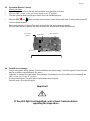
Piëzo Ignitter
(Manual) Manual knob Main valve knob
Microswitch
“O I” Switch 8 Wire Receiver Jack
Combination Control, Cover

Page.8
4.7 Setting the flame height / extinguishing the flame
* After the burner is ignited, the flame size will adjust to its maximum height automatically.
* Press the button (small) on the image of the flame to reduce the height and to switch the burner off.
(Extinguishing the flame: “STAND BY”). (Press the key for a short time to gradually reduce the flame.)
* Press the (large) button to increase the flame height. (Press the button briefly to gradually increase the
flame height)
4.8 Switching the unit off.
* Press the (small) button to reduce the flame height and to switch the burner off (“STAND BY”).
* Then press OFF to switch off the entire unit, including the pilot light.
* If the unit is out of use for a long period, set the “O I” switch on the gas control block to the “O” position
to save the batteries.
* In this case, it is also recommended you close the gas shut-off cock in the supply line.
Breakdowns:
* If the receiver is not receiving signals from the manual transmitter effectively, this could be caused by:
1. Flat batteries: replace the batteries.
2. An electronic problem: press “RESET” on the receiver.
3. Contact your fitter if the unit switched off regularly.
Important: If, for whatever reason, the pilot light goes out, you must wait 5 minutes before reigniting it.
4.9 Inserting and replacing the batteries
* The manual transmitter and receiver batteries have a life span of approximately one year. The use of alka
line batteries is recommended.
* The batteries need to be replaced when:
1. Manual transmitter: BATT appears on the display.
2. Receiver: long sound signals can be heard during ignition.
1. Manual transmitter:
* Open the small cover on the back.
* Carefully remove the 9V square battery and remove the battery from the contact holder. Do not pull the
wires!
* Connect the new battery and place the whole unit back. Close the cover.
2. Receiver:
* Carefully remove the entire receiver from the holder.
* Slide the small cover open.
* Remove the batteries from the battery holder.
* Place 4 new 1.5V batteries (type LR6 or AA) in the battery holder as shown. The spring must always be
against the negative (-) pole of the battery.
* Close the cover and place the receiver back into the holder.
If the batteries are not inserted correctly, the electronics of drive mechanism could be damaged irreparably.
Replace the batteries only when the unit is completely switched off.
Important
Use only non-metallic tools to remove the batteries
Removing batteries with a metal object may cause permanent damage to the electronic control.

Page.9
4. MANUAL CONTROL
The unit may be operated by hand if there is a defect in the remote control. To do so, the ignite (piezo)cable of
the receiver must first be removed and carefully slid into the piezo connector on the gas control block.
5.1 Igniting the fire
* Open the gas shut-off cock that has been installed in the gas pipe to the unit.
* Press the “O I” switch, on the gas control block, in the “I” position.
* Turn the motor button, on the gas control block, completely to the right. The button will make a "click”
sound.
* Turn the operating button on the gas control block, into the “MAN” position. A metal circle in the operat-
ing button will become visible.
* Push the metal circle inwards. For example, with a pen. Gas will now flow to the pilot flame.
* While keeping the metal circle pressed down, press the (square) piezo button (along the “O I” switch) sev-
eral times to ignite the pilot flame. You will be able to see whether the pilot flame is burning through the
glass window.
* If the pilot flame is alight, keep the metal circle pressed down for another 10 seconds and then let go.
Important: If the pilot light extinguishes, one should wait at least 5 minutes before repeating the
aforementioned steps.
* Turn the operating button to the ON position. The burner may or may not ignite, depending on the position
of the motor button.
* By turning the motor button to the required setting to the left, the burner will ignite and the flame size can
be adjusted.
5.2 Extinguishing the fire
Turn the motor button, on the gas control block, completely to the right. The button will make a "click” sound.
The burner will turn off. The pilot flame continues to burn.
5.3 Switching the unit off
Press the "O I” switch, on the gas control block, in the “O” position. The pilot flame will extinguish.
If the fireplace is not used for an extended period of time, we recommend closing the gas shut-off cock in the
supply line.
Important: If, for whatever reason, the pilot light extinguishes, you must wait 5 minutes before ignit-
ing the pilot light again.
Piëzo Knop
Piëzo Ignitter
(Manual) Manual knob Main valve knob
Microswitch
“O I” Switch 8 Wire Receiver Jack
Small metal circle for
Manual ignition
(Combination Control, Cover Manual position

Pag.10
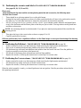
6. INSTRUCTIONS FOR MERTIK MAXITROL GV60 AND REOMOTE CONTROL:
Ensure that the fuel supplied to the unit is clean and free from particles and moisture.
Before a gas supply pipe (new or existing) is connected to the main gas pipe at the gas meter and to the gas
control block of the unit, clean and dry compressed air should been blown through it.
Cut copper pipes as well as aluminium pilot pipes must be deburred and blown clean before they are con
nected. The dust filter at the connection to the gas control block will only filter out the coarsest dirt from
the system. Fine particles are still able to reach the inside and may damage and/or adversely affect regula-
tion in the gas control block.
Heat, moisture and dust are a threat to all electronic components
Protect the electronic gas control until all construction, plastering and paintwork has been completed. If
such work cannot be avoided, then protect the control against dirt and moisture penetration by using, for
example, plastic film.
Warning
Electronic components will become permanently faulty when exposed to temperatures higher than 60°C.
Standard AA batteries will crack open at temperatures >54°C and the battery contents will damage the
electronic switches located underneath. Batteries last longest at <25°C. At >50°C the life span is around 23
weeks, this makes the use of the gas fire unnecessarily expensive.
Only install the gas control block and receiver as pre-installed at the factory
Remember that components may have to be replaced or that repairs may have to be performed at a later
date. This may be more difficult if the control is installed using a method that is different from the instruc-
tions provided here.
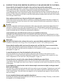
Please note:
Only place the batteries after wiring to the receiver, gas control block and pilot set is connected.
Premature connection to the energy source may damage the control’s CPU (central processor).
Ensure that the ignition cable is not near the antenna wire and that they do not cross each other.
The high voltage released at ignition may damage the sensitive receiver circuit.
This may mean that the unit becomes less responsive or not responsive at all to handset commands. (See
photograph 1 on page 16)
Loosen the antenna wire from the terminals on the receiver box
Direct the antenna wire away from the ignition cable and in the direction of the control box door.
Ensure there is no contact with metal components. Ensure there is no damage to the connection to elec-
tronic components or to the wire itself. (See photograph 1 on page 11)
Connect the wires correctly to the contact breaker behind the gas control block.
The shortest wire runs immediately back to the 1/0 switch and can be found nearest to the back of the gas
control block. The longest wire runs to one of the two connections on the receiver box and only fits on one
of the screws.
Do not tighten the contact breaker and the thermocouple connection too tightly on the gas control
block or to each other.
It is sufficient to tighten by hand and add a half a turn with an open-end spanner. Tightening too much will
break the connection to the magnetic coil below and/or the insulation around the aluminium contact pin
in the contact breaker. This may lead to the magnetic coil not opening the gas supply to the pilot and the
unit not working.
Do not extend the thermocouple supplied to the pilot set
Extending the thermocouple beyond its limit will lead to a reduction in voltage. This may, in turn, lead to
the magnetic coil not being activated.

Pag.11
Prevent leakage of the ignition spark to parts of the installation other than the ignition rod at the pilot.
Ensure the ignition cable is not in contact with the shell or other metal parts. If a cable extension is used, ensure
that connections are additionally insulated using silicone.
The receiver and the control units on the gas control block should be switched on to ensure automatic start
-up through the manual transmitter.
The oval disk on the gas control block should be turned to the ON position. The I/0 switch should be set to 1. See
photograph 2. The ignition cable should be connected to the SPARK connection point on the receiver box. See
photograph 1.
The manual transmitter has to communicate with the receiver. This has to be ‘learnt’.
Press the RESET button using a blunt object. (See photograph 3.) Continue to press this button until you hear a
short beeping sound, followed immediately by a long beeping signal. Release the button. Direct the manual trans-
mitter towards the receiver and press the arrow down until you hear a long beeping sound. The gas control button
will now move for a short period.
The manual transmitter has now learned the setting with regard to the receiver and the unit can now be ignited
using the remote control.
Please note:
Only remove batteries using non-metallic tools.
Removing batteries with a metal object may damage the electronic control permanently.
Photo 2
Photo 3
Photo 1
40 mm

Pag.12
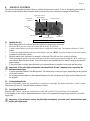
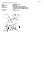
7. TECHNICAL DETAILS GV60
7
Model : Transparente (Topper)
Gas block type : Mertik GV60
Ignition : Distance operation and Piezo ignition
Gas connection : 3/8" (Internal) A=Gas intake B=Gas exhaust
C=Thermocouple connection D=Pilot burner
Unit category : B11As
Pilot flame : OP Seegas Oxipilot
D= Pilot burner
A
=C= Thermocou-

Pag.13

Pag.14
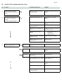
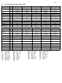
8. Mertik GV60 Troubleshooting Flow Chart
No ACTION Possible problem/cause Solution
1. Option: wall switch START:
press ON button > wall switch
works.
NO Bent pin on switch, or cable not
operating properly. Straighten pin, replace wall switch
or cable.
1. Manual transmitter START: press
both buttons to start ignition
sequence.
Beep will occur each second
NO Manual transmitter battery low. Replace battery, 9V quality
alkaline!
Receiver batteries low. Replace batteries, 1.5V AA quality
alkaline!
Optional mains adapter not
operating properly. Check mains adapter.
Check coding of transmitter and
receiver. Learn in new code, see instructions
and label on receiver.
OK Transmitter/receiver range
limited. 1. Move antenna cable, see
instructions.
2. Replace receiver.
Optional wall switch / cabling not
operating properly. Replace wall switch / cabling.
Receiver fuse blown (in older
versions only). Replace receiver.
2. Magnet unit in gas valve is
energised (audible click) NO
No beep Impulse magnet not operating
properly. Replace gas valve.
NO 3 short beeps Receiver batteries low. Replace batteries, 1.5V AA quality
alkaline!
NO 1 long beep ON/OFF switch on gas valve in
OFF position Set switch to ON.
8-wire cable between receiver and
gas valve defective / poor contact. Check cable, especially in case of
plug connection.
OK Switch cable disconnected. Check switch cable, see fig. 1 on
page 18
Motor not operating properly. Replace gas valve.
Micro switch on gas valve not
operating properly. Replace gas valve.

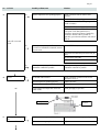
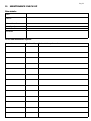
Pag.15
No ACTION Possible problem/cause Solution
3. NO Ignition components not operating properly. Check connection between cable & IGN
electrode.
Check IGN electrode spark gap.
Check IGN electrode for discharge to ground
(break in ceramic).
Check IGN cable for damage
Increase distance between IGN cable and all
metal parts. Check that spark does not
discharge to ground at location of spark plug
connection. Shorten cable if possible. If
applicable, provide extra insulation with silicon
hose etc.
Spark will occur each
second.
NO IGN sequence stops, no pilot flame.
No reaction to transmitter command (receiver
does not react).
Press RESET button, see instructions.
Add ground wire between pilot burner and gas
valve.
Do not coil the IGN cable.
Shorten IGN cable if possible.
NO IGN sequence stops, no pilot flame.
Transmitter command is possible. IGN sequence stops, no pilot flame.
Transmitter command is possible.
OK
4. Pilot lit. NO
TC and SW cable reversed. Check connection of cable to receiver and
interrupter, see fig. 1.
Impulse magnet not operating properly. Replace gas valve.
Short between interrupter and SW cable. Check connection to interrupter.
OK No gas (magnet unit drops after 30 second
audible count). Check gas supply to gas valve.
5. Sparking stops after pilot
is lit NO Short between interrupter and TC cable. Check connection to interrupter, see fig. 1
OK Electronic measuring amplifier defective. Replace receiver.
Interrupter Receiver

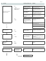
Pag.16
No ACTION Possible problem/cause Solution
6. NO Resistance in thermo
current circuit too high. Check cables and connections in
thermo current circuit.
Magnet unit drops
(audible click) Not enough heat on
thermocouple. Check position of pilot to
thermocouple and intensity of pilot
flame.
Motor turns to main gas
and pilot stays lit. Low voltage from
thermocouple. Check connections and, if necessary,
replace thermocouple. Do not
overtighten the connections!
Short because
thermocouple end is
damaged.
Replace thermocouple, do not
overtighten the connections!
NO IGN sequence stops. No
reaction to transmitter
command (receiver does
not react).
Press RESET button, see
instructions.
Add ground wire between pilot
burner and gas valve.
OK Do not coil the IGN cable.
Shorten IGN cable if possible.
7. Main burner is lit. NO Gas valve manual knob in
“MAN” position. Turn knob to “ON” position.
OK
8. Main burner stays lit. NO Too much / too little air
flow / draft at pilot, blows
out or is smothered.
Check whether restriction plate has
been correctly applied in unit, see
instructions.
Poor flue location, check correctness
of layout and connections.
OK
9. Magnet unit drops while
motor turns.
3 beeps
NO Receiver batteries low. Replace batteries, 1.5V AA quality
alkaline!
System can be switched
OFF via remote control. NO System can be
switched OFF via
ON/OFF switch.
NO Short between TC and SW
cable. Check connection to interrupter
block.
YES YES
OK OK Replace gas valve.

Pag.17
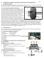
9. OPERATING INSTRUCTIONS FOR THE DUNGS AB COMBINATION
GAS REGULATOR
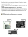
This regulator is fitted with a complete infra-red control system. This means that you can ignite the unit, smoothly
adjust the flame height and extinguish the unit using the remote control.
9.1 Infra-red remote control and its operation
The infra-red remote control allows you to comfortably control
the AB system. When in direct line of sight with the infra-red
receiver, the remote control has a range of approximately 15m
To start the system, press the buttons “ON” and “OFF” together
for at least 3 seconds. The start-up process is indicated by a se-
ries of three short tones. After the flame has lit, it can be in-
creased to the maximum height by pressing the “UP” button.
Pressing the “DOWN” button reduces the flame to its minimum
height. Pressing the “OFF” button for at least one second
switches off the system and places the unit in “Stand By" mode.
In the event of a fault in the unit (a red LED lamp lights on the
receiver), the system can be reset by pressing the “ON” and “OFF” buttons at the same time for at least 3 seconds
which will return it to the “STAND BY” mode. The “Automod” button starts automated adjustment of the system.
When automated adjustment is selected, the power of the unit automatically reduces from approximately 80% to
20% and then increase from 20% back to 80% again within a set time interval. This function can be stopped by
pressing the “Automod” button again or by pressing the “UP” or “DOWN” buttons. Depending on the individual
specification of the unit, the FOCContact knob can be used. Pressing the button engages a transistor that enables
external units with their own power supply to be switched on or off.
9.2 Igniting the gas fire.
Open the gas shut-off tap that has been fitted in the gas pipe leading to the unit. Now follow the steps described
above in “Infra-red remote control and its operation.”
Systeem "OFF"
AUTO mod / Aan / Uit
FOCContact / Aan / Uit
Led Vlamhoogte / "UP"
Vlamhoogte / "DOWN"
Systeem "ON"
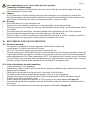
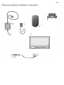
9.3 Basic system components (See page 22)
1: Modu box 4: Gas control block
2: Transformer (24 V) 5: Remote control
3: IR receiver 6: Wire harness
9.4 Connection to the gas regulation block wiring
1: Blue / Blue
2: Black / Black
3: Red / Red
4: Yellow-green
9.5 Adjusting the Gas regulation block (See adjustment values
on pages 23 and 24)
Setting the flow rate - Low setting
A Connect manometer to pressure measuring point (9)
B Ignite the fire
C Set the flow rate by turning adjustment screw 11 with a screw
driver.
- turn clockwise, to reduce "-"
- turn anti-clockwise, to increase "+"
Setting the flow rate - High setting
A Connect manometer to pressure measuring point (9)
B Ignite the fire
D Set the flow rate by turning adjustment screw 12 with a screw
driver.
- turn clockwise, to reduce "-"
- turn anti-clockwise, to increase "+"
1 2 3
9
11
12 13
mBar
- +
1 2 3
5
4

Pag.18
After completing any work: Test for leaks and check operation.
9.6 Connecting to the mains supply
The regulation equipment is fitted with an electronic control. Take into account the length of the cable
when connecting to a power socket.
9.7 Chimney
If it is connected to a chimney that had previously been connected to a wood-fuelled fire, than the flue
should be thoroughly and professionally cleaned as dirt can still become dislodged from the chimney when
used with gas. The chimney will need to be cleaned again after a couple of months.
9.8 Warning.
* Only install the unit in a well-ventilated room.
* The gas unit is only suitable for installation in a non-flammable, fire resistant mounting.
* This is an open fire so you should not place any light flammable articles nearby: care should be taken with ny
lon clothing.
* The exhaust gas outlet should have a minimum diameter that corresponds to the size of the connection.
* Protect all pipes (electric/gas) through a wall duct using a pvc tube and so forth.
* If there is a valve or slider in the exhaust gas outlet that allows the outlet to be fully or partially closed, this
should be locked in an open position using a protector connected to the control.
10. ELECTRICAL AND GAS CONNECTION
10.1 Electrical connection.
The regulator is composed of various components which should be fitted in the
correct manner. You need to provide the following:
* 230 V AC, 50 Hz power supply positioned near to the gas block fire.
* The plug and the power socket should be within reach at all times. Position the main components, namely the
control cabinet and the gas regulator combination in a place that is easily accessed. The maximum permitted
ambient temperature for all of these components is 60° C. The regulation box is simple to mount, for instance
on a wall. Remove the cover plate from the regulation box by unscrewing the 2 cover plate screws. The regu
lation box can be positioned on the assembly slots in the bottom of the regulation box.
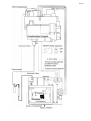
10.2 Order of installation: electrical connections.
* Connect according to local regulations.
* Determine the position for the control box and the gas regulation combination (pay attention to the maximum
length of the wire harness).
* Check that the wire harness from the gas block is connected to the Modu box.
* The ignition cable should be passed through separately on its own. (excess sparking)
* Determine the position of the infra-red receiver (the lens should remain visible to the remote control)
* Insert the power cable into the wall socket.
* If used, connect the open position protector or GTP as shown in the wiring diagram. (See page 21).
* Ensure that the ground wire is properly connected. Without this connection, ionization current protection is
not possible.
* For connections and attachments for the basic gas regulation combination (See page 22).

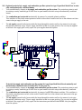
Pag.19
BASIC DIAGRAM

Pag.20
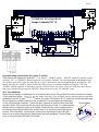
10.3 Optional protected air supply and combustion gas flue system for type II gas-fired block fires in natu
rally and mechanically ventilated homes.
* You can additionally connect an air supply and combustion gas flue system. The protection system is used
in existing or newly installed type II block fires in open hearths which are set up in mechanically ventilated
homes.
* The combustion gas is extracted mechanically by means of a protected exhaust ventilator.
This ventilator is fitted with current protection which in the event of insufficient flow in the exhaust vent inter
venes in the gas supply to the unit.
* The air supply comes directly from outside the home through the exterior walls or by means of an air pipe
through the ventilation cavity. The air supply should be locked in an open position. Gas can only be supplied
to the unit if the supply grill is fully open. Ask your supplier about the options.
Protected air supply and combustion gas flue system for type II gas-fired block fires in naturally and
mechanically ventilated homes. Exhausto EFC21 (See page 17)
* You can additionally connect an air supply and combustion gas flue system. The protection system is used
in existing or newly installed type II block fires in open hearths which are setup in mechanically ventilated
homes.
* The combustion gas is extracted mechanically by means of an EFC21 exhaust ventilator. This ventilator is
fitted with current protection which in the event of insufficient flow in the exhaust vent intervenes in the gas
supply to the unit.
* The air supply comes directly from outside the home through the exterior walls or by means of an air pipe
through the ventilation cavity. The air supply should be locked in an open position. Gas can only be supplied
to the unit if the supply grill is fully open. See the instructions provided with the EFC21. Ask your supplier
about the options.
Page is loading ...
Page is loading ...
Page is loading ...
Page is loading ...
Page is loading ...
Page is loading ...
Page is loading ...
Page is loading ...
Page is loading ...
Page is loading ...
Page is loading ...
Page is loading ...
Page is loading ...
Page is loading ...
Page is loading ...
Page is loading ...
-
 1
1
-
 2
2
-
 3
3
-
 4
4
-
 5
5
-
 6
6
-
 7
7
-
 8
8
-
 9
9
-
 10
10
-
 11
11
-
 12
12
-
 13
13
-
 14
14
-
 15
15
-
 16
16
-
 17
17
-
 18
18
-
 19
19
-
 20
20
-
 21
21
-
 22
22
-
 23
23
-
 24
24
-
 25
25
-
 26
26
-
 27
27
-
 28
28
-
 29
29
-
 30
30
-
 31
31
-
 32
32
-
 33
33
-
 34
34
-
 35
35
-
 36
36


Thermocet Transparente 120 Owner's manual
- Category
- Fireplaces
- Type
- Owner's manual
- This manual is also suitable for
Ask a question and I''ll find the answer in the document
Finding information in a document is now easier with AI
Related papers
Other documents
-
RAIS VIVA L Series Installation & Operation Manual
-
 Italkero Focus 180 User, Installation And Technical Assistance
-
 Maxitrol Mertik GV60 Operating Instructions Manual
-
 Chesney's CUBB22 User And Installation Instructions Manual
-
Empire Comfort Systems VFXI-30N-1 Owner's manual
-
Dovre 122 Owner's manual
-
-
White Mountain Hearth Loft Vent-Free Multi-Sided Burner (VFRU, VFIU) Owner's manual
-
Dovre S203.212 Owner's manual
-
Empire P)-1 Installation Instructions And Owner's Manua


