Maxitrol Mertik GV60 Operating Instructions Manual
- Type
- Operating Instructions Manual

R
R
DEUTSCH
GV60 Elektronisches Zünd- und
Steuersystem mit Fernbedienung
Bedienungsanleitung
ENGLISH
GV60 Remote Electronic Ignition and
Control System
Operating Instructions
FRANCAIS
GV60 Système d’allumage et de
commande électronique à distance
Instructions de service
NEDERLANDS
Elektronisch GV60-systeem voor
ontsteking en bediening op afstand
Bedieningshandleiding
Page is loading ...

1 / 20
© 2019 Mertik Maxitrol GmbH & Co. KG, All Rights Reserved.
ENGLISH
CONTENTS
IMPORTANT SAFETY INFORMATION ........................................... 2
INSTALLATION INSTRUCTIONS
Application ................................................................................. 3
Components .............................................................................. 3
Technical Specifications ............................................................ 4
Gas Connections ....................................................................... 5
Perform Gas Leak Test .............................................................. 6
Wiring Connections ................................................................... 6
Gas Control Knob Settings ...................................................... 12
Adjustment .............................................................................. 12
Final Check ............................................................................. 13
OPERATING INSTRUCTIONS
General Notes ......................................................................... 14
Setting the Electronic Code ..................................................... 14
To turn ON Appliance .............................................................. 15
To turn OFF Appliance ............................................................ 15
Flame Height Adjustment ........................................................ 15
To open and close Solenoid Valve/Burner ............................... 16
Light/Dimmer Operation .......................................................... 16
Circulating Fan Operation ....................................................... 16
Modes of Operation ................................................................. 16
Setting °C/24 Hour or °F/12 Hour Clock ...................................17
Setting the Time ...................................................................... 17
Setting the ON/OFF Temperatures .......................................... 17
Setting Program Timers .......................................................... 18
Manual Operation .................................................................... 18
Turn OFF Gas to Appliance ..................................................... 19
Automatic Turn Down .............................................................. 19
Automatic Shut Off .................................................................. 19
Receiver Shut Off / Turn down attributes ................................. 20

2 / 20
© 2019 Mertik Maxitrol GmbH & Co. KG, All Rights Reserved.
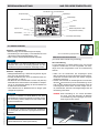
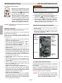
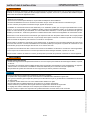
WHAT TO DO IF YOU SMELL GAS
▪ Do NOT operate any appliance.
▪ Do NOT touch any electrical switch; do NOT use any phone in your building.
▪ Immediately evacuate the area and contact the gas supplier. Follow the gas supplier’s instructions.
▪ If you cannot reach the gas supplier, call the re department.
Read these instructions carefully and completely before installing or operating. Failure to follow them could result in a re or
explosion causing property damage, personal injury, or loss of life. Service and installation must be performed by a trained / ex-
perienced service technician.
Installation and service must be performed by a qualied installer, service agency, or the gas supplier. Installation shall conform
with local codes, or in the absence of local codes, in accordance with the National Fuel Gas Code ANSI Z223.1/NFPA 54 or the
IFGC or CSA B149.1. All piping and tubing must comply with local codes and ordinances.
Use only your hand to push in or turn the gas control knobs. Never use tools. If a knob will not push in or turn by hand, do not
try to repair it. Call a qualied service technician. Force or attempted repair can result in a re or explosion.
Do NOT use a product if you suspect it has been subjected to high temperatures, damaged, tampered with, or taken apart. Do
NOT use a product if you suspect it has been under water or that liquid has seeped into the product. Any of these incidents
can cause leakage or other damage that may affect proper operation and cause potentially dangerous combustion problems.
Damper position must be in accordance with Manufacturer’s Installation Instructions and all applicable standards. Failure to
follow them could result in a re or explosion causing property damage, personal injury, or loss of life.
Do NOT store or use gasoline or other ammable vapors and liquids in the vicinity of this control or other appliances.
IMPORTANT SAFETY INFORMATION
ELECTRIC SHOCK HAZARD
▪ Read these instructions carefully. Failure to follow them could result in property damage, personal injury, or loss of life.
▪ This control must be electrically wired and operated in accordance with all codes and local regulations. Service and installation
must be performed by a trained, experienced service technician.
▪ Do NOT use the control if you suspect it may be damaged.
It is the responsibility of the OEM to consider the following:
▪ The location of the GV60 system components will signicantly effect the radio signal strength.
▪ The type of materials (e.g. sheet metal) used in the construction of the gas replace will signicantly effect the radio signal
strength.
▪ Operate the system with a dedicated mains power supply and/or batteries.
▪ Do not use near household electrical wiring and/or magnetic elds.
▪ Other transmitters using the same signal will negatively affect the radio signal strength.
▪ Adjustment of the on-board antenna on the receiver can improve signal strength.
▪ Do not store or locate the GV60 system components in a hot, cold, or humid environment.
NOTICE

3 / 20
© 2019 Mertik Maxitrol GmbH & Co. KG, All Rights Reserved.
ENGLISH
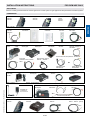
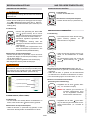
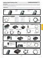
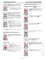
G60-ZMA3 with
connections for
EU, UK, and U.S.
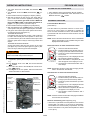
Figure 4: Additional Function RF: FAN – Light/Dimmer – Latching Solenoid
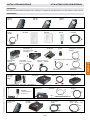
INSTALLATION INSTRUCTIONS FOR OEM USE ONLY
Figure 2: Operation
Switch Panel
with cable
G6R-SPKS…
Wall Switch US
G6R-ZWSN..-...
Wall Switch EU
G6R-ZWSE...
Touchpad
G6R-TPN…
Cable Wall Switch/Touchpad
G6R-CWSN…
Figure 3: Basic RF
Standard receiver
G6R-R3(4)AM...
Ignition Cable
G60-ZKIS...
8 Wire Cable
Combination Control – Receiver
G6R-C…
Interrupter Block
G60-ZUS...
Thermocurrent Cable
Interrupter – Receiver TC
G60-ZKIRS…
Combination Control
GV60
Thermocurrent Cable, Interrupter Block – Receiver SW
without ON/OFF switch
G60-ZKIRSWS…
or
Universal receiver
G6R-R3(4)AU...
Cable with Relay (optional)
G6R-CLB…, G6R-CDB…
or
Battery Box
G60-ZB(S)90/...
with ON/OFF switch
G60-ZSKS(L)S…
Latching Solenoid Valve
(with cable)
GV-S60…
Cable V Module – Receiver
G6R-CBV...
V Module
G6R-BU(E)…
Receiver
G6R-R3(4)AU...
Figure 6: RF 2
nd
Thermocouple Option
Figure 5: Mains Adapter
Receiver
G6R-R3(4)AUT
2nd Thermocouple Cable
G60-ZCTC...
Ground Cable
G60-ZCGTC/…
Cable with Relay
G6R-CL..., G6R-CD... (optional)
Infrared handset
G6R-HIO…
Infrared Sensor
G6R-IRC
Receiver
G6R-RIAE
Figure 7: Infrared (IR)
APPLICATION
GV60 is a battery-powered electronic remote ignition and control system for gas appliances with pilot burners and ODS systems.
Standard RF handset
G6R-H3S...
G6R-H4S...
Display RF handset
G6R-H3D...
G6R-H4D...
Timer/Thermostat RF
handset
G6R-H3T...
G6R-H4T...
Figure 1: Remotes
COMPONENTS
2nd Thermocouple G60-ZPT…

14 / 20
© 2019 Mertik Maxitrol GmbH & Co. KG, All Rights Reserved.
GENERAL NOTES
Radio Frequency Handset
433.92 MHz for Europe; 315 MHz for U.S. and for Canada..
This device complies with part 15 of the FCC Rules. Op-
eration is subject to the following two conditions: (1) This
device may not cause harmful interference, and (2) This
device must accept any interference received, including in-
terference that may cause undesired operation. Changes or
modications not expressly approved by the party respon-
sible for compliance could void the user’s authority to oper-
ate the equipment.
NOTICE
Wiring of valve and receiver must be completed before
starting ignition. Failure to do so could damage the elec-
tronics.
Batteries – Handset
▪ 1 x 9 V (alkaline recommended).
▪ Low battery indicator on handsets with display.
▪ Handsets without display: the red LED gets darker.
▪ Battery replacement is recommended after 2 years.
Batteries – Receiver
▪ 4 x 1.5 V “AA” (alkaline recommended).
▪ Low battery indication: frequent beeps for 3 seconds when
motor turns.
▪ An AC Mains Adapter may be used instead of batteries.
▪ The module for fan speed control and light/dimmer in-
cludes mains power together with batteries in the receiver
for automatic backup in case of power outage.
▪ Without using a mains adapter, battery replacement is rec-
ommended at the beginning of each heating season.
NOTICE
Only the Mertik Maxitrol AC Mains Adapter or one
preapproved by Mertik Maxitrol can be used. Use of other
adaptors can render the system inoperable.
NOTICE
The handsets, receivers, wall switches, switch panels and
touchpads are not interchangeable with previous electron-
ics (see gure 24).
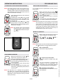
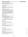
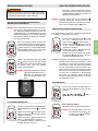
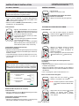
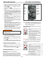
Figure 24: Receiver Reset Button
NOTICE
Replacement handsets for CSA models also must have
the same part number (see label).
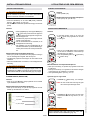
SETTING THE ELECTRONICS CODE
(First time use only.)
Radio Frequency Handset
A code is selected automatically for all Mertik Maxitrol elec-
tronics from among 65,000 random codes available. The re-
ceiver has to learn the code of the handset:
▪ Press and hold the receiver’s reset button (see gure 24)
until you hear two (2) beeps. The rst beep is short and the
second beep is long. After the second beep, release the
reset button.
▪ Within the subsequent 20 seconds press the
(small
ame) button on the handset until you hear two additional
short beeps conrming the code is set. If you hear one long
beep, this indicates the code learning sequence has failed
or the wiring is incorrect.
NOTE: This is a one time setting only, and is not required
after changing the batteries of the handset or re-
ceiver.
OPERATING INSTRUCTIONS FOR OEM USE ONLY
Figure 23: Previous handset
Light/Dimmer operation
Fan operation
Time setting
Program timer setting
Temperature
°C/24 hour or °F/12 hour Clock setting
Fan level icon
Solenoid Valve/Burner
OPEN and CLOSE
ON/OFF Temperatures setting
Battery status
Signal indicator
Modes of operation
Figure 22: Handset display

15 / 20
© 2019 Mertik Maxitrol GmbH & Co. KG, All Rights Reserved.
ENGLISH
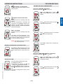
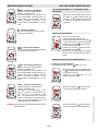
TO TURN OFF APPLIANCE
Handset
▪ Press OFF button.
Wall Switch / Touchpad / Switch Panel
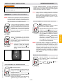
▪ Press button “B” (see gure 25).
FLAME HEIGHT ADJUSTMENT
Handset
▪ In standby mode: Press and hold (large
ame) button to increase ame height.
▪ Press and hold (small ame) button to de-
crease ame height or to set appliance at
pilot ame.
▪ For ne adjustment tap the
(large ame)
or
(small ame) buttons.
Wall Switch/Touchpad/Switch Panel (see gure 25)
▪ Press and hold button “A” to increase ame height.
▪ Press and hold button “C” to decrease ame height or to
set appliance at pilot ame.
▪ For ne adjustment tap button “A” or “C”.
Designated Low Fire and High Fire
MAN
C
▪ Double-click (small ame) button. “LO”
will be displayed.
NOTE: Flame goes to high re rst before
going to designated low re.
MAN
C
▪ Double-click (large ame) button. Flame
automatically goes to high re. “HI” will be
displayed.
If the appliance will not operate, follow the instructions
“TURN OFF GAS TO APPLIANCE” (page 19).
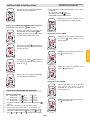
TO TURN ON APPLIANCE
When pilot ignition is conrmed, motor turns automatically
to maximum ame height.
▪ Turn MANUAL knob on valve to the ON, full counter-clock-
wise
position (see gure 27, page 19).
▪ Place ON/OFF switch (if equipped) in I (ON position).
Handset
▪ Simultaneously press the OFF and (large
ame) buttons until a short beep conrms
the start sequence has begun; release but-
tons.
▪ Continuing beeps conrm the ignition is in
process.
▪ Once pilot ignition is conrmed, there is
main gas ow.
▪ After main burner ignition the handset will
automatically go into manual mode (CSA
version, CE version).
Wall Switch / Touchpad / Switch Panel
▪ Press button “B” (see gure 25) until a short beep conrms
the start sequence has begun; release button.
▪ Continuing beeps conrm the ignition is in process.
▪ Once pilot ignition is conrmed, there is main gas ow.
If the pilot does not stay lit after several tries, turn the main
valve knob to OFF and follow the instructions “TURN OFF
GAS TO APPLIANCE” (page 19).
STANDBY MODE (Pilot Flame)
Handset
▪
Press and hold
(small ame) to set appliance at pilot ame.
Wall Switch / Touchpad / Switch Panel
▪ Press and hold button “C” (see gure 25) to set appliance
at pilot ame.
Figure 25: Switch Panel and Wall Switch/Touchpad
A) Increase ame height
B) ON/OFF
C) Decrease ame height
OPERATING INSTRUCTIONS FOR OEM USE ONLY

16 / 20
© 2019 Mertik Maxitrol GmbH & Co. KG, All Rights Reserved.
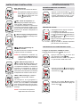
TO OPEN AND CLOSE SOLENOID VALVE/BURNER
NOTE: The latching solenoid valve cannot operate manu-
ally. If the battery runs down it will remain in the last
operating position. During normal operation the sole-
noid valve will be reset to the ON position when the
GV60 is switched OFF remotely.
▪ Upon ignition Main Burner and Decorative
Burner are ON.
▪ Simultaneously press SET and
(small
ame) buttons to switch the Burner OFF.
Printed instructions are on the battery cover
(see gure 26).
▪ Simultaneously press SET and
(large
ame) buttons to switch Burner ON. (The
AUX symbol on the display indicates the so-
lenoid valve is OPEN.)
NOTE: The operation of the AUX is blocked
in timer OFF mode, when the setting
of the
Nighttime Setback Tempera-
ture is “
”.
Figure 26: Instructions for Latching Solenoid Valve (on battery cover)
Burner OFF
Burner ON
LIGHT/DIMMER OPERATION
▪ Briey press SET button to scroll to (light
bulb) mode. Light bulb icon ashes.
▪ Press and hold
(large ame) button to
turn ON the light or increase brightness.
▪ Press and hold
(small ame) button to de-
crease brightness.
▪ In the Light/Dimmer mode, the OFF button
shuts OFF the light.
▪ If you want the light ON but no ame, press
and hold the
(small ame) button and turn
to pilot ame.
NOTE: The light bulb icon is displayed during light/dim-
mer setting only. 8 seconds after the light/dimmer
has been set, the handset will automatically go into
temperature control mode (CSA version) or manual
mode (CE version).
OPERATING INSTRUCTIONS FOR OEM USE ONLY
CIRCULATING FAN OPERATION
The circulating fan has 4 speed levels from low (1 bar) to
high (4 bars).
▪ Briey press SET button to scroll to
(fan) mode. Fan and Level icons ash.
▪ Press
(large ame) button to switch ON
and increase fan speed.
▪ Press
(small ame) button to decrease
fan speed.
▪ To turn OFF fan, press
(small ame) but-
ton until all 4 speed level bars disappear.
NOTE: 8 seconds after the fan has been set, the handset
will automatically go into temperature control mode
(CSA version) or manual mode (CE version). The
fan starts 4 minutes after the gas opens (from OFF
or from pilot) at maximum speed and goes to the
displayed level after 10 seconds. The fan stops 10
minutes after the gas is OFF or at pilot.
MODES OF OPERATION
▪ Briey pressing the SET button changes the
mode of operation in the following order:
MAN→
TEMP→ → → TEMP →
TIMER→back to the beginning
NOTE: Manual mode can also be reached by pressing either
the
(large ame) or the (small ame) button.
▪ MAN – Manual Mode
Manual ame height adjustment.
▪ – Daytime Temperature Mode
(Appliance must be in standby mode; pilot
ignited)
The room temperature is measured and
compared to the set temperature. The
ame height is then automatically adjusted
to achieve the Daytime Set Temperature.
▪ – Light/Dimmer Setting Mode
Turns light/dimmer ON and OFF and ad-
justs brightness.

17 / 20
© 2019 Mertik Maxitrol GmbH & Co. KG, All Rights Reserved.
ENGLISH
OPERATING INSTRUCTIONS FOR OEM USE ONLY
▪ Circulating Fan Setting Mode
Turns circulating fan ON and OFF and ad-
justs fan speed.
▪ – Nighttime Setback Temperature
Mode
(Appliance must be in standby mode; pilot
ignited)
The room temperature is measured and
compared to the Nighttime Setback Tem-
perature. The ame height is then auto-
matically adjusted to achieve the Nighttime
Setback Temperature.
▪ TIMER – Timer Mode
(Appliance must be in standby mode; pilot
ignited)
The Timers P1 and P2 (Program 1, Pro-
gram 2) each can be programmed to go ON
and OFF at specic times. For instructions
see Timer Programming Mode.
NOTE: The display shows the set tempera-
ture every 30 seconds.
SETTING °C/24 HOUR OR °F/12 HOUR CLOCK
▪ Press OFF and (small ame) button until
display changes from Fahrenheit/12 hour
clock to Celsius/24 hour clock and vice ver-
sa.
SETTING THE TIME
▪ The Time display will ash after either:
a) Installing the battery or
b) Simultaneously pressing the
(large
ame) and
(small ame) buttons.
▪ Press
(large ame) button to set the hour.
▪ Press
(small ame) button to set the min-
ute.
▪ Press OFF or simply wait to return to man-
ual mode.
SETTING THE ON/OFF TEMPERATURES
Setting the “DAYTIME” Temperature
DEFAULT SETTINGS:
TEMP, 74 °F / 23 °C
▪ Briey press SET button to scroll to
TEMP. Hold the SET button until the TEMP
ashes.
▪ Press (large ame) button to increase
Daytime Set Temperature.
▪ Press (small ame) button to decrease
Daytime Set Temperature.
▪ Press OFF or simply wait to complete pro-
gramming.
Setting the “NIGHTTIME SETBACK” Temperature
DEFAULT SETTINGS:
TEMP, “ ” (OFF)
▪ Briey press SET button to scroll to
TEMP mode. Hold the SET button until the
Temperature ashes.
▪ Press (large ame) button to increase
Nighttime Setback Temperature.

18 / 20
© 2019 Mertik Maxitrol GmbH & Co. KG, All Rights Reserved.
▪ Press (small ame) button to decrease
Nighttime Setback Temperature.
▪ Press OFF or simply wait to complete pro-
gramming.
SETTING PROGRAM TIMERS
Default Settings
CE: Program 1: P1
: 6:00 P1 : 8:00
Program 2: P2
: 23:50 P2 : 23:50
CSA: Program 1: P1
: 6:00
am
P1 : 8:00
am
Program 2: P2 : 11:50
pm
P2 : 11:50
pm
▪ 2 ON times can be programmed per day.
▪ CE: The day starts at 0:00, ends at 23:50.
▪ CSA: The day starts at 12:00
am
, ends at 11:50
pm
.
▪ The ON/OFF times have to be programmed in the order P1
≤ P1 < P2 ≤ P2 .
▪ If P1
= P1 or P2 = P2 the timer is deactivated.
▪ To have the re over night, it can be set:
CE: P2
23:50 and P1 0:00
CSA: P2
11:50
am
and P1 12:00
am
▪ Select Timer Mode by briey pressing the
SET button.
Setting P1 ON Time
▪ Hold the SET button until P1 and are dis-
played and the time ashes.
▪ Set the hour by pressing the (large ame)
button.
OPERATING INSTRUCTIONS FOR OEM USE ONLY
▪ Set the minutes by pressing the (small
ame) button.
Setting P1 OFF Time
▪ Briey press SET button to scroll to setting
P1 OFF time. P1 and
are displayed and
the time ashes.
▪ Set the hour by pressing the (large ame)
button.
▪ Set the minutes by pressing the (small
ame) button.
Setting P2 ON Time
▪ Briey press SET button to scroll to setting P2 ON time. P2
is displayed and the time ashes.
▪ See instructions "Setting P1 ON Time".
Setting P2 OFF Time
▪ Briey press SET button to scroll to setting P2 OFF time.
P2
is displayed and the time ashes.
▪ See instructions "Setting P1 OFF Time".
▪ This concludes programming Timers P1 and P2. Press
OFF or wait. The handset will automatically save your
changes.
MANUAL OPERATION
(Only possible, when MANUAL knob is used)
Access to the pilot burner is only required for ignition with a
match.
When turning main valve knob, do NOT force. Knob has a
slip clutch that clicks until the end stops are reached. This
allows for manual ame height adjustment as well as adjust-
ment to pilot standby position.
1. STOP! Read the safety information included before pro-
ceeding.

19 / 20
© 2019 Mertik Maxitrol GmbH & Co. KG, All Rights Reserved.
ENGLISH
OPERATING INSTRUCTIONS FOR OEM USE ONLY
2. Turn main valve knob to the OFF, full clockwise
position.
3. Turn MANUAL knob to the MAN, full clockwise
po-
sition.
4. Place ON/OFF switch (if equipped) in O (OFF position).
5. Wait ve (5) minutes to clear out any gas. Verify that no
gas is in the area around the appliance, including near
the oor. If you detect gas STOP! Follow “WHAT TO
DO IF YOU SMELL GAS” in the safety information on
page 2. If no gas is present, proceed to step 6.
6. Place ON/OFF switch (if equipped) in I (ON position).
7. With the MANUAL knob in MAN position a manual pilot
valve operator and piezo ignitor (optional) are accessible.
8. Fully push down manual pilot valve operator and hold in,
to start pilot gas ow (see gure 27).
IGNITION WITH MATCH:
Immediately light the pilot with a match, while continuing
to hold in the manual pilot valve operator for about one
(1) minute after the pilot is lit. Release manual pilot valve
operator. If pilot does not stay lit, wait ve (5) minutes and
repeat.
IGNITION WITH PIEZO IGNITOR:
Change the ignition cable from the receiver to the valve
(see gure 27). Push in the piezo ignitor to ignite. If pilot
does not stay lit, wait ve (5) minutes and repeat.
If the pilot does not stay lit after several tries, turn the main
valve knob to OFF and proceed to step 12.
9. If applicable, replace pilot access panel before proceed-
ing.
10. Turn MANUAL knob to the ON, full counter-clockwise
position.
11. Turn main valve knob to the full ON, full counter-clock-
wise
position.
12. If the appliance will not operate, follow the instructions
“TURN OFF GAS TO APPLIANCE”.
Figure 27: Combination control, cover
8 Wire
receiver jack
Micro switch
MANUAL knob
in MAN position
Main valve knob
in OFF position
Manual pilot
valve operator
Piezo ignitor
(optional)
ON/OFF switch
(optional) in
ON Position
Connection
piezo ignitor
tab 2.8 x 0.8 mm
TO TURN OFF GAS TO APPLIANCE
1. Place ON/OFF switch (if equipped) in O (OFF position).
2. If gas control is accessible turn main valve knob to the
OFF full clockwise
position.
AUTOMATIC TURN DOWN
8 Hour No Motor Movement
(CSA Version)
The valve will turn to pilot ame if there is no motor move-
ment for an 8-hour period. To deactivate or activate the
8-hour no motor movement turn down, the handset must be
synchronized with the Receiver and the Receiver must be
powered ON.
NOTE:
8-hour No Motor Movement turn down is the default
setting. Deactivation is only possible using the G6R
display/thermostat handset.
Deactivate 8-hour no motor movement turn down
1. Press and hold the Down button.
2. Install the battery in the handset while con-
tinuing to press and hold the Down button.
3. Continue to press and hold the Down but-
ton for 8 sec.
4. During the 8 sec., 8h is displayed and the
last set status (ON/OFF) will ash.
5. When deactivation is completed, 8h and
OFF will appear on the display for 4 sec.
6. The Receiver conrms deactivation with 3
short beeps.
NOTE: Deactivation remains in effect after changing the bat-
teries in the Receiver and Handset.
Activate 8-hour no motor movement turn down
1. Press and hold the Up button.
2. Install the battery in the handset while con-
tinuing to press and hold the Up button.
3. Continue to press and hold the Up button
for 8 sec.
4. During the 8 sec., 8h is displayed and the
last set status (ON/OFF) will ash.
5. When activation is completed, 8h and ON
will appear on the display for 4 sec.
6. The Receiver conrms activation with 2
short beeps.
NOTE: Activation remains in effect after changing the batteries
in the Receiver and Handset.
Receiver Overheating (G6R-R3(4)AU(T) only)
▪ Valve turns to pilot ame if the temperature in the receiver
is higher than 176 °F (80 °C) or 140 °F (60 °C) when batter-
ies installed in the receiver battery compartment. The main
burner comes back on only when the temperature is below
176 °F (80 °C).

20 / 20
© 2019 Mertik Maxitrol GmbH & Co. KG, All Rights Reserved.
OPERATING INSTRUCTIONS FOR OEM USE ONLY
1 Hour Turn Down for Special Receiver
(optional; requires special receiver and handset software)
▪ The valve will turn to pilot ame if there is no change in
ame height over a 1 hour period.
AUTOMATIC SHUT OFF
Low Battery Receiver
▪ With low battery power in the receiver the system shuts off
the re completely. This will not happen if the power supply
is interrupted.
On-Demand Pilot (5 Day Shut-Off)
▪
This green feature eliminates gas energy consumption dur-
ing extended appliance inactivity. When the appliance is
inactive for an extended period of time the system automat
-
ically extinguishes the pilot. This feature helps the consum-
er realize cost benets by automatically eliminating energy
consumption during non-heating months and limited use.
▪ The programmed length of inactivity to activate the system
is specied by the appliance manufacturer and cannot be
altered in the eld.
2
nd
Thermocouple Shut Off
(optional)
▪ The system shuts off the re if the main burner does not
completely ignite approximately 20 seconds after ignition
or after pushing
(large ame) button.
NOTE: Before the next ignition there is a 2 minute waiting
period. If the thermocouple is then still too hot, you
will hear a long beep.
RECEIVER SHUT OFF / TURN DOWN ATTRIBUTES
EU-Versions (CE)
G6R-R4AM (Standard)
▪ 176 °F (80 °C) turn down to pilot is NOT supported
▪ 5-day shut off. (
If no motor movement for
5 days.)
G6R-R4AU (Universal)
▪ Turn down to pilot at 176 °F (80 °C) (with and without con-
nected module)
▪ Turn down to pilot at 140 °F (60 °C) when batteries installed
in the receiver battery compartment
▪ 5-day shut off. (
If no motor movement for
5 days.)
U.S. Versions (CSA)
G6R-R3AM (Standard)
▪ 176 °F (80 °C) turn down to pilot is NOT supported
▪ 7-day shut off. (If no motor movement for 7 days.)
G6R-R3AU (Universal)
▪ Turn down to pilot at 176 °F (80 °C) (with and without con-
nected module)
▪ 7-day shut off. (If no motor movement for 7 days.)
▪ 8 hour turn down to pilot. (If no motor movement for 8 hours.)
▪ Turn down to pilot at 140 °F (60 °C) when batteries installed
in the receiver battery compartment.
Page is loading ...
Page is loading ...
Page is loading ...
Page is loading ...
Page is loading ...
Page is loading ...
Page is loading ...
Page is loading ...
Page is loading ...
Page is loading ...
Page is loading ...
Page is loading ...
Page is loading ...
Page is loading ...
Page is loading ...
Page is loading ...
Page is loading ...
Page is loading ...
Page is loading ...
Page is loading ...
Page is loading ...
Page is loading ...
Page is loading ...
Page is loading ...
Page is loading ...
Page is loading ...
Page is loading ...
Page is loading ...
Page is loading ...
Page is loading ...
Page is loading ...
Page is loading ...
Page is loading ...
Page is loading ...
Page is loading ...
Page is loading ...
Page is loading ...
Page is loading ...
Page is loading ...

© 2019 Mertik Maxitrol GmbH & Co. KG, All Rights Reserved.
GV60-B-OI-EN.DE.FR.NL-05.2019
Exclusive Distributor North America
for Mertik Maxitrol
Maxitrol Company
23555 Telegraph Rd., PO Box 2230
Southfield, MI 48037-2230
USA
Tel: + 1 248-356-1400
Fax: + 1 248-356-0829
www.maxitrol.com
Exclusive Distributor Europe
for Maxitrol Company
Mertik Maxitrol GmbH & Co. KG
Warnstedter Str. 3, 06502 Thale
GERMANY
Tel: + 49 3947 400-0
Fax: + 49 3947 400-200
www.mertikmaxitrol.com
R
R
-
 1
1
-
 2
2
-
 3
3
-
 4
4
-
 5
5
-
 6
6
-
 7
7
-
 8
8
-
 9
9
-
 10
10
-
 11
11
-
 12
12
-
 13
13
-
 14
14
-
 15
15
-
 16
16
-
 17
17
-
 18
18
-
 19
19
-
 20
20
-
 21
21
-
 22
22
-
 23
23
-
 24
24
-
 25
25
-
 26
26
-
 27
27
-
 28
28
-
 29
29
-
 30
30
-
 31
31
-
 32
32
-
 33
33
-
 34
34
-
 35
35
-
 36
36
-
 37
37
-
 38
38
-
 39
39
-
 40
40
-
 41
41
-
 42
42
-
 43
43
-
 44
44
-
 45
45
-
 46
46
-
 47
47
-
 48
48
-
 49
49
-
 50
50
-
 51
51
-
 52
52


Maxitrol Mertik GV60 Operating Instructions Manual
- Type
- Operating Instructions Manual
Ask a question and I''ll find the answer in the document
Finding information in a document is now easier with AI
in other languages
- français: Maxitrol Mertik GV60
- Deutsch: Maxitrol Mertik GV60
- Nederlands: Maxitrol Mertik GV60
Other documents
-
RAIS VIVA L Series Installation & Operation Manual
-
Regency LRI3E User guide
-
Real Fyre 01V Remote Owner's manual
-
Thermocet Transparente 100 Owner's manual
-
White Mountain Hearth Slope Glaze Burners Vent-Free, Intermittent Pilot (VFSE, VFSV) Owner's manual
-
 Regency Fireplace Products Maxitrol GV60 Owner's manual
-
-
Valor GV60PAK Owner's manual
-
Empire VFRL24P Installation Instructions And Owner's Manual
-
DREO DR-HTF007 User manual
