4
For information on safety guidelines, regulatory compliances, EMI/EMF compatibility, accessibility, and related topics, see the
Extron Safety and Regulatory Compliance Guide on the Extron website.
© 2015 - 2020 Extron Electronics — All rights reserved. www.extron.com All trademarks mentioned are the property of their respective owners.
Worldwide Headquarters: Extron USA West, 1025 E. Ball Road, Anaheim, CA 92805, 800.633.9876
68-2515-50 Rev. B
03 20
TLP Pro 320M • Setup Guide (Continued)
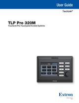
Rear Panel Features
A
Power connector — Connect a 12 VDC, 1.0 A power supply
(not included) to this 2-pole, 3.5 mm captive screw connector.
NOTES:
• The TLP Pro 320M ships without a power supply.
Either the 12 VDC, 1.0 A power supply or the power
injector must be purchased separately.
• If a 12 VDC supply and a power injector are both
connected to the TLP Pro 320M, the power injector
takes precedence. If a power loss from the power
injector is detected, the touchpanel switches
seamlessly to the 12 VDC supply without needing a
system reboot.
ATTENTION:
• The TLP Pro 320M can use a 12 VDC desktop power supply and is also Power over Ethernet (PoE 802.3af, class3)
compliant. Do not connect either power supply before reading the Attention in the “Power Supply” section of the
TLPPro320M User Guide.
• Le TLP Pro 320M peut utiliser une source d’alimentation externe 12 Vcc, et est également compatible avec
l’alimentation POE via Ethernet (PoE 802.3af, classe 3). Ne branchez pas de sources d’alimentation externes avant
d’avoir lu les mises en garde dans la section «PowerSupply» du TLPPro320M User Guide.
B
Reset button — This recessed button allows the unit to be reset. The TLP Pro 320M has four reset modes (see below) that are
initiated by pressing the reset button. For more information about these different modes, see the TLPPro 320M User Guide.
C
Reset LED— Indicates power status and reset status of the device.
D
Network and Power over Ethernet (PoE) connector — Is used to connect the touchpanel to the LAN using a twisted pair cable,
terminated with an RJ-45 connector. The connector can also be used with a power injector (not provided).
An Extron IP Link Pro control processor must also be connected to the same network as the TouchLink Pro touchpanel.
Reset Modes: a Brief Summary
The TLP Pro 320M provides the following reset modes:
• Use Factory Firmware — Press and hold the Reset button (gure 4,
B
) while applying power to the unit. Use this mode to
revert to factory rmware in the event of rmware failure.
• Reset All IP Settings — Press and hold the Reset button for 6 seconds. After the Reset LED (
C
) blinks twice, release and
momentarily press the Reset button. Use this mode to reset all network settings to factory default values without affecting user-
loaded les.
• Reset to Factory Defaults — Press and hold the Reset button for 9 seconds. After the Reset LED blinks three times, release
and momentarily press the Reset button. Use this mode to return the touchpanel to factory default settings, including passwords
and removes user-loaded les (such as a user-provided SSL certicate). The factory congured passwords for all accounts on this
device have been set to the device serial number.
Passwords can be changed during conguration. They are case sensitive.
NOTE: If the device is reset to default settings, the passwords are reset to the default password, which is extron (for
either admin or user).
A
A
B
B
C
C
D
D
Figure 4. TLP Pro 320M Rear Panel
Status
Exit
INFO
Model
Part Number
Firmware Version
PoE
TLP Pro 320M
60-1451-02
1.00.0010.b004
Active
NETWORK
DHCP Off
INF
o
e
art
um
er
rmw
r
r
n
o
ro 320
-
5
-
1.
.
1
.
4
ct
v
NETWORK
HCP
ff
Network
Display
Audio
Advanced
Status
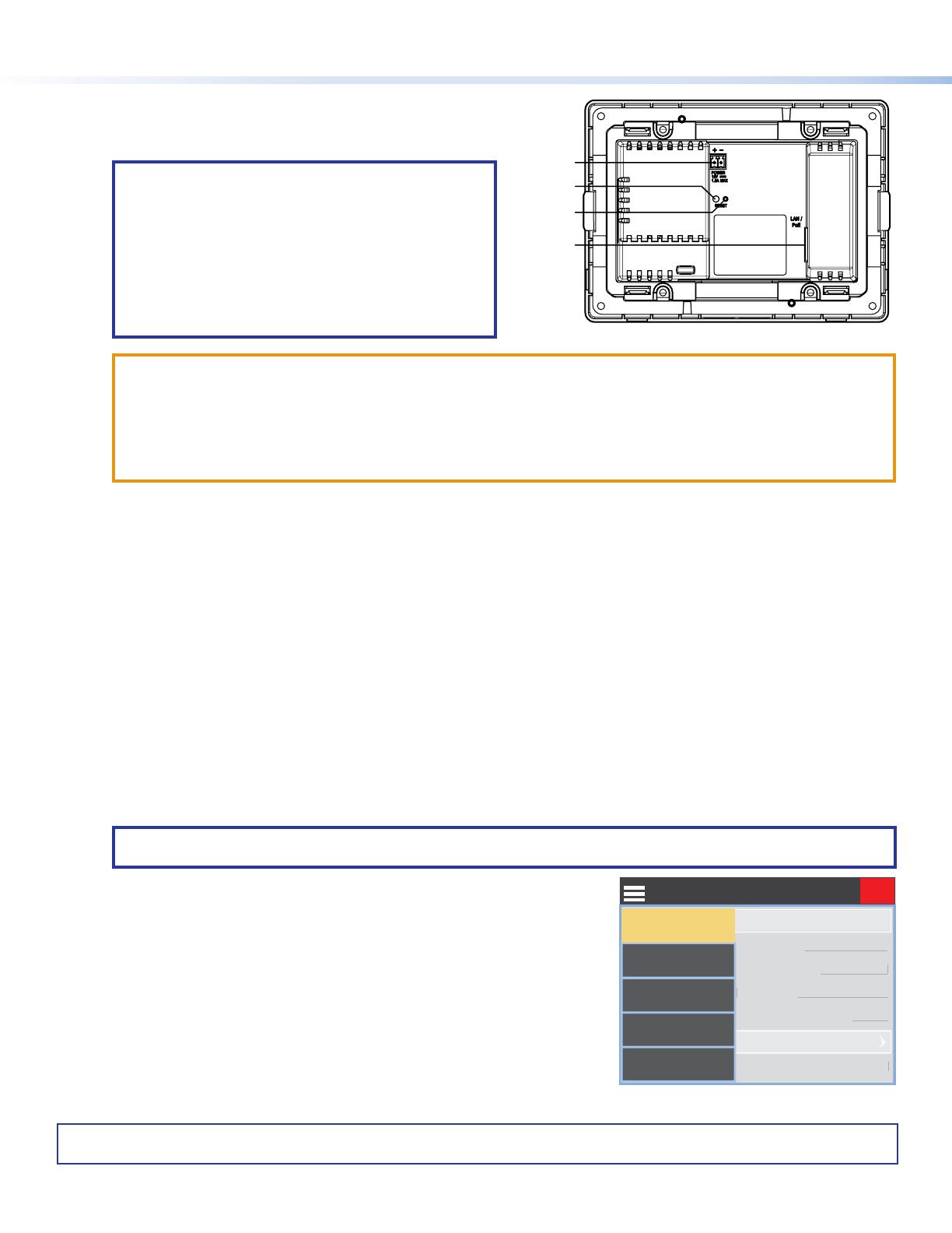
Figure 5. Setup Menu
• Enable or disable the DHCP Client — Press the Reset button ve times
consecutively and then release the button.
• If DHCP was enabled, it is now disabled. The Reset LED blinks three times.
• If DHCP was disabled, it is now enabled. The Reset LED blinks six times.
Setup Menu
The on-screen setup menu opens on the TLP screen when the menu button is
pressed (see figure3,
F
on page 3).
There are ve different screens:
Status, Network, Display, Audio, and Advanced.
The screens can be selected by touching the menu button at the top of the screen
and touching the appropriate on-screen button (shown in gure 5). For more
information, see the TLPPro 320M User Guide.