Black Box KVXLC-100, KVXLCF-100 User manual
- Category
- Network extenders
- Type
- User manual
This manual is also suitable for

24/7 TECHNICAL SUPPORT AT 1.877.877.2269 OR VISIT BLACKBOX.COM
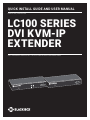
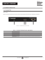
LC100 SERIES
DVI KVM-IP
EXTENDER
K V X LC-100, K V X L C F -100
QUICK INSTALL GUIDE AND USER MANUAL
PWR
PWR
Serial over IP
DVI KVM Extender Transmitter
Serial over IP
DVI KVM Extender Receiver

2
TABLE OF CONTENTS
NEED HELP?
LEAVE THE TECH TO US
LIVE 24/7
TECHNICAL
SUPPORT
1.8 77.87 7.2269
1. 8 7 7. 8 7 7. 2 2 6 9 BLACKBOX.COM
QUICK INSTALLATION GUIDE .......................................................................................................................................................... 3
1. SPECIFICATIONS ........................................................................................................................................................................... 4
2. OVERVIEW ...................................................................................................................................................................................... 6
2.1 Introduction ...............................................................................................................................................................................................6
2.2 Features ....................................................................................................................................................................................................6
2.3 What’s Included ........................................................................................................................................................................................ 6
2.4 Hardware Description .............................................................................................................................................................................. 7
2.4.1 Transmitter ..........................................................................................................................................................................................................7
2.4.2 Receiver................................................................................................................................................................................................................9
3. CONNECTION DIAGRAM ............................................................................................................................................................ 11
4. INSTALL ATION ............................................................................................................................................................................ 12
4.1 Factory Default Settings ........................................................................................................................................................................12
4.2 Connect All Devices to the Switch ........................................................................................................................................................12
5. FIRMWARE UPGRADE ................................................................................................................................................................. 14
APPENDIX A. REGULATORY INFORMATION ................................................................................................................................ 16
A.1 FCC Statement .......................................................................................................................................................................................16
A.2 NOM Statement .....................................................................................................................................................................................17
APPENDIX B. DISCLAIMER/TRADEMARKS ................................................................................................................................. 18
B.1 Disclaimer ...............................................................................................................................................................................................18
B.2 Trademarks .............................................................................................................................................................................................18

3
1. 8 7 7. 8 7 7. 2 2 6 9 BLACKBOX.COM
NEED HELP?
LEAVE THE TECH TO US
LIVE 24/7
TECHNICAL
SUPPORT
1.8 77.87 7.2269
QUICK INSTALLATION GUIDE
Follow these steps to install the extender:
1. If you have the fiber models, install the SFPs in the transmitter and receiver. Compatible SFPs from Black Box are listed in the table
below.
COMPATIBLE SFP MODULES
PART NUMBER DESCRIPTION DISTANCE
1-GBPS CONNECTIONS
LFP411 SFP 1250-Mbps, 850-nm Multimode Fiber, LC 550 m
LFP413 SFP 1250-Mbps, 1310-nm Single-mode Fiber, LC 10 km
LFP415 SFP 1250-Mbps, Extended Diagnostics, 1000BASE-T, SerDes Interface, RJ-45 100 m
NOTE: Black Box extenders will also support generic SFP modules.
2. Connect the video source to the Transmitter (Computer Unit).
3. Connect the monitor to the Receiver unit.
4. Use CATx cables (EIA/TIA 568B industry standard compliant) or fiber cables for connection between Transmitter/Receiver and
Gigabit LAN Switch.
5. Apply the proper power to all connecting devices.
NOTES:
a. We recommend using the highest quality materials (cables, SFP, etc.) to ensure optimal transmission quality.
b. If the screen does not display when you connect the computer:
1. Make sure the device cables are correctly and firmly attached.
2. Set your display device’s (TV, monitor, etc.) input source as DVI.
3. Check the PC BIOS configuration of the video output setting.
4. Connect your video source to the Display DIRECTLY to check if the video signal gets through.

4
1. 8 7 7. 8 7 7. 2 2 6 9 BLACKBOX.COM
NEED HELP?
LEAVE THE TECH TO US
LIVE 24/7
TECHNICAL
SUPPORT
1.8 77.87 7.2269
CHAPTER 1: SPECIFICATIONS
TABLE 1-1. TRANSMITTER SPECIFICATIONS
Console Connection
Video Output N/A
Serial Control Port N/A
Host Connection
Video Input (1) DVI-I female
Local Out Video Connection
Local Out (1) DVI-I female
Link Port
RJ-45 (KVXLC-100 transmitter) CATx cable – max. length: 330 feet (100 meters)
SFP (KVXLCF-100 transmitter) Fiberoptic cable – max. length: 33,000 feet (10 km)
USB Interface
Host (1) USB Type B female
Device N/A
Audio
2-way analog audio (1) Line In, (1) Line Out
General
LED indicator Power: White LED
DDC Supported DDC, DDC2, DDC2B
Max. Video Resolution 1920 x 1200 @ 60 Hz
OS Compatibility OS Independent
Housing material Chassis Metal
Operating Temperature 32 to 122° F (0 to 50° C)
Storage Temperature -4 to +140° F (-20 to +60° C)
Relative Humidity 0 to 80%
Power Supply External 5-VDC, 2-A power supply
Dimensions 1.06" H x 3.27" W x 7.09" D (2.7 x 8.3 x 18 cm)
Weight
KVXLC-100 transmitter: 0.79 lb. (0.36 kg);
KVXLCF-100 transmitter: 0.77 lb. (0.35 kg)

5
1. 8 7 7. 8 7 7. 2 2 6 9 BLACKBOX.COM
NEED HELP?
LEAVE THE TECH TO US
LIVE 24/7
TECHNICAL
SUPPORT
1.8 77.87 7.2269
CHAPTER 1: SPECIFICATIONS
TABLE 1-2. RECEIVER SPECIFICATIONS
Console Connection
Video Output (1) DVI-I female
Serial Control Port (1) DB9 male
Host Connection
Video Input N/A
Link Port
RJ-45 (KVXLC-100 receiver) CATx cable – max. length: 330 feet (100 meters)
SFP (KVXLCF-100 receiver) Fiberoptic cable – max. length: 33,000 feet (10 km)
USB Interface
Host N/A
Device (4) USB Type A female
Audio
2-way analog audio (1) MIC In, (1) Speaker Out
General
LED indicator Power: White LED
DDC Supported DDC, DDC2, DDC2B
Max. Video Resolution 1920 x 1200 @ 60 Hz
OS Compatibility OS Independent
Housing material Chassis Metal
Operating Temperature 32 to 122° F (0 to 50° C)
Storage Temperature -4 to +140° F (-20 to +60° C)
Relative Humidity 0 to 80%
Power Supply External 5-VDC, 2-A power supply
Dimensions 1.06” H x 3.27” W x 7.09” D (2.7 x 8.3 x 18 cm)
Weight
KVXLC-100 receiver: 0.84 lb. (0.38 kg);
KVXLCF-100 receiver: 0.81 lb. (0.37 kg)

6
1. 8 7 7. 8 7 7. 2 2 6 9 BLACKBOX.COM
NEED HELP?
LEAVE THE TECH TO US
LIVE 24/7
TECHNICAL
SUPPORT
1.8 77.87 7.2269
CHAPTER 2: OVERVIEW
2.1 INTRODUCTION
The LC100 Series DVI KVM-IP Extender enables you to locally use a DVI/VGA monitor, USB keyboard/mouse/other devices, speaker and
microphone to operate a remote computer, server or other IT device.
There are two models of the LC100 Series DVI KVM-IP Extender: one is KVXLC-100 via a CATx link, and the other is KVXLCF-100 via a
fiberoptic link. Each extender consists of a transmitter (TX) and a receiver (RX).
2.2 FEATURES
Supports DVI and VGA input/output video quality up to 1920 x 1200 @ 60 Hz.
Reaches video/USB/RS-232/audio extension distance up to 330 feet (100 meters) over CATx cable for model KVXLC-100;
up to 33,000 feet (10 km) over fiberoptic cable for model KVXLCF-100.
Offers transparent USB 2.0/1.1 extension.
Uses analog audio LINE-IN/LINE-OUT extension.
Supports bi-directional RS-232 control communication.
Firmware upgradable.
2.3 WHAT’S INCLUDED
KVXLC-100:
(1) DVI KVM-IP CATx Extender Transmitter (TX)
(1) DVI KVM-IP CATx Extender Receiver (RX)
(2) 5-VDC, 2-A power supplies
KVXLCF-100:
(1) DVI KVM-IP Fiber Extender Transmitter (TX)
(1) DVI KVM-IP Fiber Extender Receiver (RX)
(2) 5-VDC, 2-A power supplies

7
1. 8 7 7. 8 7 7. 2 2 6 9 BLACKBOX.COM
NEED HELP?
LEAVE THE TECH TO US
LIVE 24/7
TECHNICAL
SUPPORT
1.8 77.87 7.2269
CHAPTER 2: OVERVIEW
2.4 HARDWARE DESCRIPTION
2.4.1 TRANSMITTER
FRONT PANEL
Figure 2-1 shows the front panel that is common to both the CATx and the fiber transmitter. Table 2-1 describes its components.
1 2 3 4
FIGURE 2-1. TRANSMITTER FRONT PANEL
TABLE 2-1. TRANSMITTER FRONT-PANEL COMPONENTS
NUMBER IN FIGURE 2-1 COMPONENT DESCRIPTION
1 PWR LED Lights when power to the transmitter is ON
2 Audio jack Connects to analog audio input for audio extension
3 Audio jack Connects to analog audio output for audio extension
4 DB9 connector Connects to source device’s RS-232 port for serial over IP RS-232 extension

8
1. 8 7 7. 8 7 7. 2 2 6 9 BLACKBOX.COM
NEED HELP?
LEAVE THE TECH TO US
LIVE 24/7
TECHNICAL
SUPPORT
1.8 77.87 7.2269
CHAPTER 2: OVERVIEW
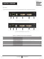
BACK PANEL
Figures 2-2 and 2-3 show the back panels of the CATx and fiber transmitters. Table 2-2 describes their components.
1 2 3 4 5 6
FIGURE 2-2. CATX TRANSMITTER BACK PANEL
1 2 3 4 5 6
FIGURE 2-3. FIBER TRANSMITTER BACK PANEL
TABLE 2-2. TRANSMITTER BACK-PANEL COMPONENTS
NUMBER IN FIGURE 2-2 OR 2-3 COMPONENT DESCRIPTION
1 Ground screw Links to ground
2
For CATx model: RJ-45 connector
For Fiber model: SFP cage
For CATx Model: CATx link
For Fiber model: Install fiber SFP module here
3 USB Type B connector Connects to source device’s USB port
4 DVI In port Connects to source device’s signal for DVI/VGA extension
5 DVI Out port Connects to local out
6 Power connector Links to 5-VDC power supply

9
1. 8 7 7. 8 7 7. 2 2 6 9 BLACKBOX.COM
NEED HELP?
LEAVE THE TECH TO US
LIVE 24/7
TECHNICAL
SUPPORT
1.8 77.87 7.2269
CHAPTER 2: OVERVIEW
2.4.2 RECEIVER
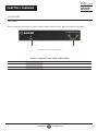
FRONT PANEL
Figure 2-4 shows the front panel that is common to both the CATx and the fiber receiver. Table 2-3 describes its components.
1 2
FIGURE 2-4. RECEIVER FRONT PANEL
TABLE 2-3. RECEIVER FRONT-PANEL COMPONENTS
NUMBER IN FIGURE 2-4 COMPONENT DESCRIPTION
1 PWR LED Lights when power to the receiver is ON
2 DB9 connector Connects to sink device’s RS-232 port for serial over IP RS-232 extension

10
1. 8 7 7. 8 7 7. 2 2 6 9 BLACKBOX.COM
NEED HELP?
LEAVE THE TECH TO US
LIVE 24/7
TECHNICAL
SUPPORT
1.8 77.87 7.2269
CHAPTER 2: OVERVIEW
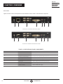
BACK PANEL
Figures 2-5 and 2-6 show the back panels of the CATx and fiber receivers. Table 2-4 describes their components.
1 2 3 4 5 6 7
FIGURE 2-5. CATX RECEIVER BACK PANEL
1 2 3 4 5 6 7
FIGURE 2-6. FIBER RECEIVER BACK PANEL
TABLE 2-4. RECEIVER BACK-PANEL COMPONENTS
NUMBER IN FIGURE 2-5 OR 2-6 COMPONENT DESCRIPTION
1 Ground screw Links to ground
2
For CATx model: RJ-45 connector
For Fiber model: SFP cage
For CATx Model: CATx link
For Fiber model: Install fiber SFP module here
3 (4) USB Type A connectors Connects to USB device’s ports for extension
4 DVI Out port Connects to sink device’s signal for DVI/VGA extension
5 Phone jack Links to analog audio input for audio extension
6 Phone jack Links to analog audio output for audio extension
7 Power connector Links to 5-VDC power supply

11
1. 8 7 7. 8 7 7. 2 2 6 9 BLACKBOX.COM
NEED HELP?
LEAVE THE TECH TO US
LIVE 24/7
TECHNICAL
SUPPORT
1.8 77.87 7.2269
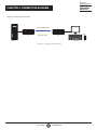
CHAPTER 3: CONNECTION DIAGRAM
Figure 3-1 shows a typical connection.
Source Console
TX
RX
CATx UTP/STP Cable
Fiberoptic Cable
OR
FIGURE 3-1. CONNECTION DIAGRAM

12
1. 8 7 7. 8 7 7. 2 2 6 9 BLACKBOX.COM
NEED HELP?
LEAVE THE TECH TO US
LIVE 24/7
TECHNICAL
SUPPORT
1.8 77.87 7.2269
CHAPTER 4: INSTALL ATION
4.1 FACTORY DEFAULT SETTINGS
Below are the factory default baud rate settings for the DVI KVM-IP Extender’s serial ports.
Baud rate: 115,200 bps
Data bits: 8
Parity: None
Stop bits: 1
If the default settings do not meet your needs, contact Black Box Technical Support at 877-877-2269 or info@blackbox.com.
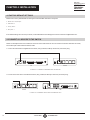
4.2 CONNECT ALL DEVICES TO THE SWITCH
NOTE: The examples below show a CAT5e/6 connection for the CATx Extender. The connections for the Fiber Extender are similar,
but use fiberoptic cable instead of CAT5e/6 cable.
1. Connect the transmitter to a Gigabit Ethernet switch, using a CAT5e/6 cable up to 330 feet (100 meters) long.
+
LINK USB
DVI-I IN
+
DVI-I OUT
TX
Switch
FIGURE 4-1. CONNECT TRANSMITTER TO SWITCH
2. Connect the receiver to the same Ethernet switch, using a CAT5e/6 cable up to 330 feet (100 meters) long.
+
DVI-I OUTLINK
DC 5V
+
Switch
RX
FIGURE 4-2. CONNECT RECEIVER TO SAME SWITCH

13
1. 8 7 7. 8 7 7. 2 2 6 9 BLACKBOX.COM
NEED HELP?
LEAVE THE TECH TO US
LIVE 24/7
TECHNICAL
SUPPORT
1.8 77.87 7.2269
CHAPTER 4: INSTALL ATION
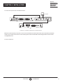
3. Connect the computer to the same Ethernet switch.
+
DVI-I OUT
LINK USB
DC 5V
+
+
DVI-I IN
+
DVI-I OUT
RX
TX Switch
Computer
FIGURE 4-3. CONNECT COMPUTER TO SAME SWITCH
NOTE: We recommend that you only have 1 TX and 1 RX connected to the network switch at any time to eliminate any IP address
conflicts. If you require more units to be on the network, please contact our Black Box Technical Support team at 877-877-2269
or inf[email protected].
4. Power on all devices.

14
1. 8 7 7. 8 7 7. 2 2 6 9 BLACKBOX.COM
NEED HELP?
LEAVE THE TECH TO US
LIVE 24/7
TECHNICAL
SUPPORT
1.8 77.87 7.2269
CHAPTER 5: FIRMWARE UPGRADE
Firmware files for upgrading the DVI KVM-IP Extender transmitter and receiver are usually different, unless otherwise specified.
The file for the transmitter contains the word “tx.”
The file for the receiver contains the word “rx.”
The firmware upgrade procedure is similar to the procedure of changing Baud Rate setting. Do the following two steps first before
upgrading the firmware.
STEP 1: Download a Zeroconf Networking Tool
STEP 2: Connect the Computer and Configure TCP/IP
To upgrade the firmware of either DVI KVM-IP Extender device:
1. Go to the computer that is connected to the Ethernet switch. See STEP 2: Connect the Computer and Configure TCP/IP.
2. Launch Bonjour browser, or any zeroconf tool you have downloaded.
3. Select “Web Server (HTTP)” to display the IP addresses of both the transmitter and receiver.
dvi-gatewayXXX: This refers to the transmitter. XXX is the transmitter’s number.
dvi-clientXXX: This refers to the receiver. XXX is the receiver’s number.
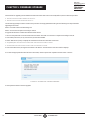
4. Launch the web browser, and type the transmitter’s IP address. The transmitter’s web user interface displays.
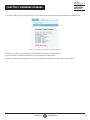
5. To select the appropriate firmware file for the transmitter, click the System tab > Update Firmware section > Browse.
FIGURE 5-1. SYSTEM TAB > UPDATE FIRMWARE
6. Click Upload to start the firmware upgrade.

15
1. 8 7 7. 8 7 7. 2 2 6 9 BLACKBOX.COM
NEED HELP?
LEAVE THE TECH TO US
LIVE 24/7
TECHNICAL
SUPPORT
1.8 77.87 7.2269
CHAPTER 5: FIRMWARE UPGRADE
7. A firmware update progress message is shown on-screen. Wait until the firmware upgrade is done and finishes its reboot process.
FIGURE 5-2. FIRMWARE UPDATE PROGRESS SCREEN
8. Now you can verify the current version by clicking the System tab >Version Information section.
9. Type the receiver’s IP address in the browser to show the receiver’s web user interface.
10. Repeat the same firmware upgrade steps for the receiver. Note that the firmware file is different from the transmitter.

16
1. 8 7 7. 8 7 7. 2 2 6 9 BLACKBOX.COM
NEED HELP?
LEAVE THE TECH TO US
LIVE 24/7
TECHNICAL
SUPPORT
1.8 77.87 7.2269
APPENDIX A: REGULATORY INFORMATION
A.1 FCC CLASS A STATEMENT
This equipment generates, uses, and can radiate radio-frequency energy, and if not installed and used properly, that is, in strict
accordance with the manufacturer’s instructions, may cause interference to radio communication. It has been tested and found to
comply with the limits for a Class A computing device in accordance with the specifications in Subpart B of Part 15 of FCC rules,
which are designed to provide reasonable protection against such interference when the equipment is operated in a commercial
environment. Operation of this equipment in a residential area is likely to cause interference, in which case the user at his own
expense will be required to take whatever measures may be necessary to correct the interference.
Changes or modifications not expressly approved by the party responsible for compliance could void the user’s authority to operate
the equipment.
This digital apparatus does not exceed the Class A limits for radio noise emission from digital apparatus set out in the Radio
Interference Regulation of Industry Canada.
Le présent appareil numérique n’émet pas de bruits radioélectriques dépassant les limites applicables aux appareils numériques
de la classe A prescrites dans le Règlement sur le brouillage radioélectrique publié par Industrie Canada.

17
1. 8 7 7. 8 7 7. 2 2 6 9 BLACKBOX.COM
NEED HELP?
LEAVE THE TECH TO US
LIVE 24/7
TECHNICAL
SUPPORT
1.8 77.87 7.2269
APPENDIX A: REGULATORY INFORMATION
A.2 NOM STATEMENT
1. Todas las instrucciones de seguridad y operación deberán ser leídas antes de que el aparato eléctrico sea operado.
2. Las instrucciones de seguridad y operación deberán ser guardadas para referencia futura.
3. Todas las advertencias en el aparato eléctrico y en sus instrucciones de operación deben ser respetadas.
4. Todas las instrucciones de operación y uso deben ser seguidas.
5. El aparato eléctrico no deberá ser usado cerca del agua—por ejemplo, cerca de la tina de baño, lavabo, sótano mojado o cerca de
una alberca, etc.
6. El aparato eléctrico debe ser usado únicamente con carritos o pedestales que sean recomendados por el fabricante.
7. El aparato eléctrico debe ser montado a la pared o al techo sólo como sea recomendado por el fabricante.
8. Servicio—El usuario no debe intentar dar servicio al equipo eléctrico más allá a lo descrito en las instrucciones de operación.
Todo otro servicio deberá ser referido a personal de servicio calificado.
9. El aparato eléctrico debe ser situado de tal manera que su posición no interfiera su uso. La colocación del aparato eléctrico
sobre una cama, sofá, alfombra o superficie similar puede bloquea la ventilación, no se debe colocar en libreros o gabinetes que
impidan el flujo de aire por los orificios de ventilación.
10. El equipo eléctrico deber ser situado fuera del alcance de fuentes de calor como radiadores, registros de calor, estufas u otros
aparatos (incluyendo amplificadores) que producen calor.
11. El aparato eléctrico deberá ser connectado a una fuente de poder sólo del tipo descrito en el instructivo de operación, o como
se indique en el aparato.
12. Precaución debe ser tomada de tal manera que la tierra fisica y la polarización del equipo no sea eliminada.
13. Los cables de la fuente de poder deben ser guiados de tal manera que no sean pisados ni pellizcados por objetos colocados
sobre o contra ellos, poniendo particular atención a los contactos y receptáculos donde salen del aparato.
14. El equipo eléctrico debe ser limpiado únicamente de acuerdo a las recomendaciones del fabricante.
15. En caso de existir, una antena externa deberá ser localizada lejos de las lineas de energia.
16. El cable de corriente deberá ser desconectado del cuando el equipo no sea usado por un largo periodo de tiempo.
17. Cuidado debe ser tomado de tal manera que objectos liquidos no sean derramados sobre la cubierta u orificios de ventilación.
18. Servicio por personal calificado deberá ser provisto cuando:
A: El cable de poder o el contacto ha sido dañado; u
B: Objectos han caído o líquido ha sido derramado dentro del aparato;o
C: El aparato ha sido expuesto a la lluvia; o
D: El aparato parece no operar normalmente o muestra un cambio en su desempeño; o
E: El aparato ha sido tirado o su cubierta ha sido dañada.

18
1. 8 7 7. 8 7 7. 2 2 6 9 BLACKBOX.COM
NEED HELP?
LEAVE THE TECH TO US
LIVE 24/7
TECHNICAL
SUPPORT
1.8 77.87 7.2269
APPENDIX B: DISCLAIMER/TRADEMARKS
B.1 DISCLAIMER
Black Box Corporation shall not be liable for damages of any kind, including, but not limited to, punitive, consequential or cost of cover
damages, resulting from any errors in the product information or specifications set forth in this document and Black Box Corporation
may revise this document at any time without notice.
B.2 TRADEMARKS USED IN THIS MANUAL
Black Box and the Black Box logo type and mark are registered trademarks of Black Box Corporation.
Any other trademarks mentioned in this manual are acknowledged to be the property of the trademark owners.

19
1. 8 7 7. 8 7 7. 2 2 6 9 BLACKBOX.COM
NEED HELP?
LEAVE THE TECH TO US
LIVE 24/7
TECHNICAL
SUPPORT
1.8 77.87 7.2269
NOTES
__________________________________________________________________________________________________
__________________________________________________________________________________________________
__________________________________________________________________________________________________
__________________________________________________________________________________________________
__________________________________________________________________________________________________
__________________________________________________________________________________________________
__________________________________________________________________________________________________
_
_________________________________________________________________________________________________
__________________________________________________________________________________________________
__________________________________________________________________________________________________\
__________________________________________________________________________________________________
__________________________________________________________________________________________________
__________________________________________________________________________________________________
__________________________________________________________________________________________________
_________________________________________________________________________________________________
__________________________________________________________________________________________________
__________________________________________________________________________________________________
__________________________________________________________________________________________________

NEED HELP?
LEAVE THE TECH TO US
LIVE 24/7
TECHNICAL
SUPPORT
1.87 7.877.2269
© COPYRIGHT 2019. BLACK BOX CORPORATION. ALL RIGHTS RESERVED.
KVXLC-100_QIG-USER_REV1.PDF
-
 1
1
-
 2
2
-
 3
3
-
 4
4
-
 5
5
-
 6
6
-
 7
7
-
 8
8
-
 9
9
-
 10
10
-
 11
11
-
 12
12
-
 13
13
-
 14
14
-
 15
15
-
 16
16
-
 17
17
-
 18
18
-
 19
19
-
 20
20


Black Box KVXLC-100, KVXLCF-100 User manual
- Category
- Network extenders
- Type
- User manual
- This manual is also suitable for
Ask a question and I''ll find the answer in the document
Finding information in a document is now easier with AI
in other languages
Related papers
-
Black Box IC282A User manual
-
-
-
-
-
-
-
-
-
Black Box IC408A-R2 User manual
Other documents
-
Blackbox ICU504A User manual
-
Rose electronics Orion User manual
-
Binary B-300-USB2-CATX Quick start guide
-
Crestron USB-EXT-2-LOCAL User manual
-
Raritan Cat5 Reach DVI HD User guide
-
-
-
A-Neuvideo ANI-HDB70 User manual
-
-