MiTAC Getac W130 Specification
- Category
- Notebooks
- Type
- Specification
This manual is also suitable for


2
1 General system Description ........................................................................................5
1.1 System Overview .............................................................................................5
1.2 System Hardware Parts....................................................................................7
1.3 Major Component Introduction .......................................................................9
1.3.1 CPU Module .........................................................................................9
1.3.2 System frequency ICS950810...............................................................9
1.3.3 Intel 855-GM GMCH IGUI 3D Graphic DDR/SDR Chipset.............10
1.3.4 Memory System.................................................................................. 11
1.3.5 Display ................................................................................................ 11
1.3.6 HUB Interface for ICH4 .....................................................................14
1.3.7 I/O Controller Hub: INTEL 82801DBM ............................................14
1.3.9 Keyboard controller Hitachi H8/3437 ................................................17
1.3.10 Fax/Modem module ..........................................................................18
1.3.11 FAST ETHERNET CONTROLLER integrated ICH-4M ................18
1.3.12 PCMCIA controller_ ENE CB1410 + ENE CP2211........................19
1.3.13 AC”97 Code ALC202 .......................................................................19
1.3.14 Thermal sensor_ ADM1021A...........................................................20
2 Motherboard Function Description...........................................................................21
2.1 Hot Key Function...........................................................................................21
2.2 Power on/off/suspend/resume button.............................................................21
2.3 Cover Switch..................................................................................................22
2.4 LED Indicators...............................................................................................22
2.5 Battery status..................................................................................................23
2.6 CMOS Battery ...............................................................................................23
2.7 I/O Port...........................................................................................................23
3 Peripheral ..................................................................................................................26
3.1 LCD PANEL..................................................................................................26
3.2 HDD...............................................................................................................26
3.3 Keyboard........................................................................................................26
3.4 Track Pad Synaptic ........................................................................................26
3.5 Memory..........................................................................................................27
3.6 Modem MDC.................................................................................................27
4 Power Management ..................................................................................................28
4.1 System Management Mode............................................................................28
4.2 Battery Life ....................................................................................................29
4.3 Other power management functions ..............................................................29
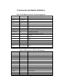
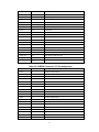
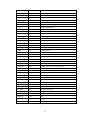
5 Connector and Switch Definition..............................................................................30

3
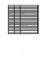
6 System View .............................................................................................................38
6-1 Front View .....................................................................................................38
6-2 Bottom View..................................................................................................38
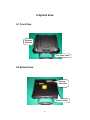
6-3 Left-Side View...............................................................................................39
6-4 Right-Side View ............................................................................................39
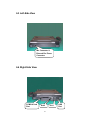
6-5 Rear View ......................................................................................................40
6-6 Top-open View...............................................................................................40
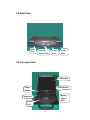
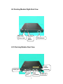
6-7 Docking Module Front View.........................................................................41
6-8 Docking Module Left-Side View...................................................................41
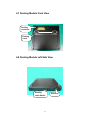
6-9 Docking Module Right-Side View ................................................................42
6-10 Docking Module Rear View ........................................................................42
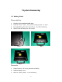
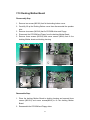
7 System Disassembly .................................................................................................43
7-1 Battery Pack...................................................................................................43
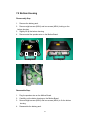
7-2 Bottom Housing.............................................................................................44
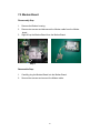
7-3 Modem Board ................................................................................................45
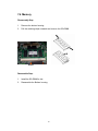
7-4 Memory .........................................................................................................46
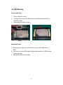
7-5 HDD Module .................................................................................................47
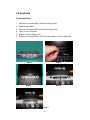
7-6 Keyboard .......................................................................................................48
7-7 LCD Panel .....................................................................................................50
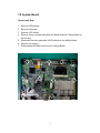
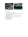
7-8 System Board.................................................................................................51
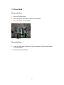
7-9 Touch Pad ......................................................................................................53
7-10 Docking Mother Board................................................................................54
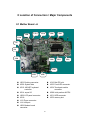
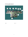
8 Location of Connectors / Major Components...........................................................56
8-1 Mother Board –A...........................................................................................56
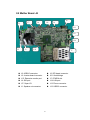
8-2 Mother Board –B ...........................................................................................57
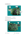
8-3 D/D Board-A .................................................................................................58
8-4 D/ D Board-B.................................................................................................58
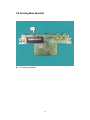
8-5 Docking Main Board-A .................................................................................59
8-6 Docking Main Board-B .................................................................................60
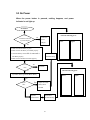
9 Trouble Shooting.......................................................................................................61
9-1 No Power .......................................................................................................63
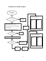
9-2 Battery Can Not Be Charged .........................................................................64
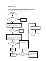
9-3 No display......................................................................................................65
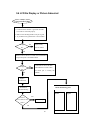
9-4 LCD No Display or Picture Abnormal ..........................................................66
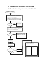
9-5 External Monitor No Display or Color Abnormal.........................................67
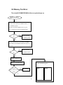
9-6 Memory Test Error ........................................................................................68
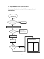
9-7 Keyboard and Touch –pad Test Error ............................................................69
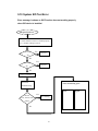
9-8 System SIO Test Error...................................................................................70

4
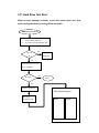
9-9 Hard Drive Test Error ....................................................................................71
9-10 System USB Port Test Error........................................................................72
9-11 System Audio Failure ..................................................................................73
9-12 PC-Card Socket Failure ...............................................................................74
10 System Exploded views & Circuit Diagram...........................................................75

5
1 General system Description
1.1 System Overview
The LightNote W130 is a rugged and high portability industrial computer. The
W130 also can connect with a docking to the capability of FLOPPY and
CD-ROM and I/O device. The W130 model will support Intel Centrino mobile
technology with Pentium-M Processors LV 1.1G, 1.2G with Micro-FCBGA,
12W in TDP and 1Mb L2 Cache.
This system is based on PCI architecture, which have standard hardware
peripheral interface. The power management complies with Advanced
Configuration and Power Interface (ACPI 2.0). It also provides easy
configuration through CMOS setup, which is built in system BIOS software
and can be pop-up by pressing F2 at system start up or warm reset
.
System also provides icon LEDs to display system status, such as Power
indicator, HDD/CDROM, NUM LOCK, CAP LOCK, SCROLL LOCK,
SUSPEND MODE and Battery charging status. It also one USB port.
The memory subsystem supports One JEDEC-standard 200-pin, small-outline,
dual in-line memory module (SODIMM), support PC2100 and up to 1GB DDR
SDRAM.
The W130 includes the 855GM chipset components GMCH and the ICH4-M.
The Accelerated Hub Architecture interface (the chipset component
interconnect) is designed into the chipset to provide an efficient, high
bandwidth, communication channel between the GMCH and the ICH4-M.
The GMCH component contains a processor system bus (PSB) controller, a
graphics controller, and a memory controller, while providing an LVDS
interface and two DVO ports. The ICH4-M component integrates USB host
controllers (supporting the USB 1.1 and USB 2.0 specification), an Ultra ATA
100/66/33 controller, a LAN controller, and an AC’97 digital controller, while
providing interfaces for PCI and LPC devices,.
To provide for the increasing number of multimedia applications, the AC97
CODEC ALC201 is integrated onto the motherboard.

6
A full set of software drivers and utilities are available to allow advanced
operating systems such as Windows2000 and WindowsXP to take full
advantage of the hardware capabilities such as bus mastering IDE,
Windows2000-ready Plug & Play, and Advance configuration and power
interface (ACPI 2.0).
Following chapters will have more detail description for each individual
sub-systems and functions.
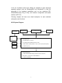
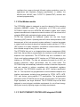
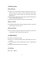
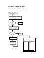
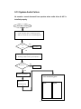
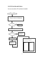
W130 System Diagram:
Primary Battery
D/D BD
1:DC IN
Touch Screen
12.1” LCD/Touch Screen Inverter BD
W130 Mother Board
1:Intel Pentium-M LV 1.1G/1.2G
2:One 200pin DDR SO-DIMM Socket (max: 1GB)
3:USB*2, RS232*1 (COM1), Modem *1 (RJ-11), LAN*1 (RJ-45),VGA*1(DB15)
4:PCMCIA*1(Type II)
W1300 Docking Board
1: USB*2, RS232*2(COM1.COM2), PIO PORT*1,PS2*1,CRT OUT*1
2: MIC IN Con.*1,Line Out Con.*1,Mono Speaker*1
3:
FLOPPY
*
1,CD
-
ROM
*
1
Ke
y
board
Trace PAD

7
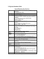
1.2 System Hardware Parts
Internal Marketing Specifications
CPU
Intel Pentium M Processor LV1.1GHz in µ-FCBGA package
FSB 400MHz
CPU Thermal ceiling: 12W
Core logic
Intel 855GM Chipset + ICH4-M
L2 Cache
On-die 1MB L2 Cache
System BIOS
512KB Flash EEPROM
Includes System BIOS, VGA BIOS, plug & play, and ACPI 2.0
capability
Boot from IDE devices and LAN, USB CD-ROM
Suspend to DRAM / HDD
PC2001 compliance
Memory One 200-pin PC2100 DDR SODIMM socket for memory
expansion
Supports 200MHz and 266MHz DDR devices
Standard: 256MB Max: 1GB
VGA
855GM integrate graphics controller
Integrated 32-bit 3D/2D gfx core with Dynamic Video Memory
Technology
Support DirectX® 8.1
Support AGP 4X
Dual View function
LCD/CRT simultaneous display capability
Video
Memory
Shared system memory 64MB
Display
12.1” TFT XGA (1024x768) LCD
12.1” touch screen (Optional)
Optional Sunlight Readable Panel (Transflective LCD)
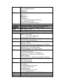
Structure
1-spindle
HDD
Standard: 40GB, Integrated, Support Ultra DMA-33/66/100
2.5” 9.5mm height with damper protect
Keyboard
W
ater-proof membrane keyboard, Backlight function
(Optional)
Rubber keyboard with back-light (Optional)
Pointing
Device
A touch-sensitive control pad with Microsoft Win Mouse
function coexist
PCMCIA
Type II x 1 - Card Bus support
Communicati
on
10/100 Base-T LAN
56K, V90. Modem
802.11b Wireless LAN (Optional)
(Supports Intel PRO/Wireless 2100 LAN mini-PCI type 3B
adapter and Intel PROset software)
Wireless Modem (DataTAC/PRM240 or GPRS/GSM or CDMA
or IDEN(5mm)) (Optional)
Audio
A
C97 audio support

8
MS-Sound compatible
Built-in one speaker (Mono)
Microphone-in
Earphone-out
I/O Port
Serial port × 1
V
GA port x 1
USB 2.0 port x 2
DC input x1
Docking Port x1
RJ-11x1 for 56Kbps Software Modem port
RJ-45 100 Base-T LAN port
Microphone-in & Earphone out ports
Battery
- Support 9 cells Li-Ion Battery
AC adapter
- Universal AC adapter -Input: 100-240v, 50/60Hz AC.
Dimensions
10.8” * 9.4” * 1.7” / 276mm * 239mm * 43mm
Weight
Goal is under 7.2 lbs
Software
Support Windows 2000 / Windows XP
Environmental Standard (Main System)
Temperature
IEC 68-2-1,2,14 / MIL-STD-810F, Method 501.4, 502.4
Operating: 0
o
C to 50
o
C
-20
o
C to 50
o
C (Optional)
Non-operating: -40
o
C to 70
o
C
Humidity
According to IEC 68-2-30 / MIL-STD-810F, Method 507.4
5% to 95% RH, non-condensing
Altitude
According to IEC 68-2-13 / MIL-STD-810F, Method 500.4
Operating: 15,000ft
Non-operating: 40,000ft; altitude change rate: 2,000 ft/min
Shock
According to IEC 68-2-27 / MIL-STD-810F, Method 516.5
Operating: 15g, 11 ms, half sine wave
Non-operating: 50g, 11 ms, half sine wave
Vibration
According to IEC 68-2-6
Sinusoidal wave vibration:
Operating: 10~55Hz/0.075, 55~500Hz/1.0g
Non-operating: 10~55Hz/0.15, 55~500Hz/2.0g
Random vibration:
MIL-STD-810F, 514.5 - high way truck vibration exposure
Drop
According to IEC 68-2-32 / MIL-STD-810F, Method 516.5
3 Feet height free drop
T
est surface: steel plate
ESD
According to IEC1000-4-2
Air Discharge:
0KV~8KV(included), no any error
8KV~15KV, allow soft error
Contact Discharge:
0KV~4KV(included), no any error
4KV~ 8KV, allow soft error
Enclosure
According to IEC 529, MIL-STD-810F, IP 51
Regulation
FCC part 15, Subpart B, Class B, UL, CUL, TUV, Win key
Options Removable Options:

9
Docking board (Serial Port x2, USB2.0 x2, Parallel x1, VGA
Port x1,
DB26 (Male) x1)
External Battery charger
Factory Options:
HDD heater for low temp. –4
o
F (-20℃) to 122
o
F (50℃)
Membrane keyboard with backlight
Rubber keyboard with backlight
W
ireless LAN (802.11b)
W
ireless Modem (DataTAC/PRM240 or GPRS/GSM or CDMA
or IDEN (5mm))
12.1” transflective LCD
12.1” touch screen
1.3 Major Component Introduction
1.3.1 CPU Module
Intel Pentium-M Processors with Micro-FCBGA package.
The first Intel mobile processor with the Intel NetBurst micro-architecture
which features include hyper-pipelined technology, a rapid execution
engine, a 400MHz system, an execution trace cache, advanced dynamic
execution, advanced transfer cache, enhanced floating point and
multi-media unit, and Streaming SIMD Extensions 2 (SSE2).
The Streaming SIMD Extensions 2 (SSE2) enable break-through levels of
performance in multimedia applications including 3-D graphics, video
decoding/encoding, and speech recognition.
Use Source-Synchronous Transfer (SST) of address and data to improve
performance by transferring data four times per bus clock.
Support Enhanced Intel SpeedStep technology, which enables real-time
dynamic switching of the voltage and frequency between two performance
modes.
1.3.2 System frequency ICS950810
Programmable output frequency, divider ratios, output rise/fall time, output
skew.
Programmable spread percentage for EMI control.
Watchdog timer technology to reset system if system malfunctions.
Programmable watchdog safe frequency.

10
Support I2C Index read/write and block read/write operations.
Use external 14.318MHz crystal.
1.3.3 Intel 855-GM GMCH IGUI 3D Graphic DDR/SDR Chipset
Intel 855-GM GMCH IGUI Host Memory Controller integrates a high
performance host interface for Intel Banias processor, a high performance
2D/3D Graphic Engine, a high performance memory controller, an AGP
4X interface, and Intel®’ I/O Hub architecture INTEL 82801DBM ICH4-M.
Intel 855-GM GMCH Host Interface features the AGTL & AGTL+
compliant bus driver technology with integrated on-die termination to
support Intel Pentium-M processors. 855-GM GMCH provides a 12-deep
In-Order-Queue to support maximum outstanding transactions up to 12. It
integrated a high performance 2D/3D Graphic Engine, Video Accelerator
and Advanced Hardware Acceleration MPEGI/MPEGII Video Decoder for
the Intel Pentium-M series based PC systems. It also integrates a high
performance 2.1GB/s DDR266 Memory controller to sustain the
bandwidth demand from the integrated GUI or external AGP master, host
processor, as well as the multi I/O masters. In addition to integrated GUI,
855-GM GMCH also can support external AGP slot with AGP 1X/2X/4X
capability and Fast Write Transactions. A high bandwidth and mature
Intel®’ I/O Hub architecture is incorporated to connect 855-GM GMCH
and INTEL 82801DBM ICH4-Mtogether. Intel®’ I/O Hub architecture is
developed into three layers, the Multi-threaded I/O Link Layer delivering
1.2GB bandwidth to connect embedded DMA Master devices and external
PCI masters to interface to Multi-threaded I/O Link layer, the
Multi-threaded I/O Link Encoder/Decoder in INTEL 82801DBM ICH4-M to
transfer data w/ 533 MB/s bandwidth from/to Multi-threaded I/O Link layer
to/from 855-GM GMCH, and the Multi-threaded I/O Link Encoder/Decoder
in 855-GM GMCH to transfer data w/ 533 MB/s from/to Multi-threaded I/O
Link layer to/from INTEL 82801DBM ICH4-M.
An Unified Memory Controller supporting DDR266 DRAM is incorporated,
delivering a high performance data transfer to/from memory subsystem
from/to the Host processor, the integrated graphic engine or external AGP
master, or the I/O bus masters. The memory controller also supports the
Suspend to RAM function by retaining the CKE# pins asserted in ACPI S3
state in which only AUX source deliver power. The 855-GM GMCH adopts
the Shared Memory Architecture, eliminating the need and thus the costs

11
of the frame buffer memory by organizing the frame buffer in the system
memory. The frame buffer size can be allocated from 8MB to 64MB.
Features
Processor/Host Bus Support
Intel
®
Pentium-M processor
2X Address, 4X data
Support host bus Dynamic Bus Inversion (DBI)
Supports system bus at 400MT/s (100 MHz)
Supports 64-bit host bus addressing
8-deep In-Order-Queue
AGTL+ bus driver technology with integrated GTL termination resistors
and low voltage operation (1.05V)
Supports Enhanced Intel® SpeedStepTM Technology (EIST) and
Geyserville III
Support for DPWR# signal to Pentium-M processor for PSB power
management
1.3.4 Memory System
Directly supports one DDR channel, 64-bts wide (72-b with ECC).
Supports 200-MHz and 266-MHz DDR devices with unbuffered.
PC1600/PC2100 DDR(with ECC).
Supports 128-Mb, 256-Mb and 512-Mbit technologies providing maximum
capacity of 1-GB with only x 16 devices.
All supported devices have 4 banks.
Supports up to 16 simultaneous open pages.
Supports page sizes of 2KB, 4KB, 8KB, and 16KB. Page size is
individually selected for every row.
UMA support only.
1.3.5 Display
Analog Display Support
350 MHz integrated 24-bit RAMDAC that can drive a standard progressive
scan analog monitor up to 1800x1350 @ 85 Hz.
Accompanying I2C and DDC channels provided through multiplexed
interface Hotplug and display support
Dual independent pipe with single display support Simultaneous: Same

12
images and native display timings on each display device
DVO (DVOB) support
Digital video out port DVOB with 165-MHz dot clock on 12-bit interface
Variety of DVO devices channel
Compliant with DVI Specification 1.0, thereby providing support for a flat
panel up to 2048x1536 pixel resolution, or digital CRT up to 1920x1080
pixel resolution
Dedicated LFP (local flat panel) interface
Single or dual channel LVDS panel support up to SXGA+ panel resolution
with frequency range from 25MHz to 112MHz per channel
SSC support of 0.5%, 1.0%, and 2.5% center and down spread with
external SSC clock
Supports data format of 18 bpp
LCD panel power sequencing compliant with SPWG timing specification
Compliant with ANSI/TIA/EIA –644-1995 spec
Integrated PWM interface for LCD backlight inverter control
Bi-linear Panel fitting
Tri-view support through LFP interface, DVO ports and CRT
Internal Graphics Features
Core Frequency
Display Core frequency of 133MHz
Render Core frequency of 133MHz
2D Graphics Engine
Optimized 128 bit BLT engine
Ten programmable and predefined monochrome patterns
Alpha Stretch Blt (via 3D pipeline)
Anti-aliased lines
Hardware-based BLT Clipping & Scissoring
32-bit Alpha Blended cursor
Programmable 64*64 3-color Transparent cursor
Color Space Conversion
3 Operand Raster BLTs
8-bit, 16-bit, and 32-bit color
ROP support
DIB translation and Linear/Title addressing
3D Graphics Engine
3D Setup and Render Engine
Viewpoint Transform and Perspective Divide

13
Triangle Lists, Strips and Fans support
Indexed Vertex and Flexible Vertex formats
Pixel accurate Fast Scissoring and Clipping operation
Backface Culling support
DirectX
TM
and OGL Pixelization rules
Anti-Aliased Lines support
Sprite Points support
Zone Rendering
Provides the highest sustained fill rate performance in 32-bit color and
24-bit W mode
High quality performance Texture Engine
266 MegaTexel/speak performance
Per Pixel Perspective corrected Texture Mapping
Single Pass Texture Compositing (Multi-Texture) at rate
Enhanced Texture Blending functions
Twelve Level of Detail MIP Map Sizes from 1x1 to 2Kx2K
Numerous Texture formats including 32-bit RGBA
Alpha and Luminance Maps
Texture Chromakeying
Bilinear, Trilinear, Anisotropic MIP-Mapped Filtering
Cubic Environment Reflection Mapping
Embossed Bump-mapping
DXTn Texture Decompression
3D Graphics Rasterrization enhancements
One Pixel per Clock
Flat and Gouraud Shading
Color Alpha Blending for Transparency
Vertex and Programmable Pixel Fog and Atmospheric effects
Color Specular Lighting
Vertex and Programmable Pixel Fog and Atmospheric effects
Z Bais support
Dithering
Line and Full-Scence Anti-Aliasing
16 and 24-bit Z Buffering
16 and 24-bit W Buffering
8-bit Stencil Buffering
Double and Triple Render Buffer support
16 and 32 –bit color

14
Destination Alpha
Vertex Cahec
Maximum 3D resolution of 1600x1200 x32 bpp at 85 Hz
Optimal 3D resolution supported
Fast Clear support
ROP support
1.3.6 HUB Interface for ICH4
266 MB/s point to point hub interface to ICH4-M
66-M Hz base clock
Supports the following traffic types to the ICH4-M
Hub interface-to DRAM
CPU-to-Hub interface
Messaging
MSI interrupt messages
Power Management state change
SMI, SCI, and SERR error indication
Power Management
SMRAM space remapping to A0000h (128-KB)
Supports extended SMRAM space above 256- MB ,additional 1 MB TSEG
from top of Memory, cacheable (cacheability controlled by CPU)
APM rev 1.2 compliant power management
Supports Suspend to System Memory(S3),Suspend to Disk(S4) and Hard
Off/Total Reboot(S5)
ACPI 1.0b 2.0 Support
1.3.7 I/O Controller Hub: INTEL 82801DBM
The INTEL 82801DBM ICH4-M integrates three Universal Serial Bus 2.0
Host Controllers, the Audio Controller with AC 97 Interface, the IDE
Master/Slave controllers, and Intel®’ I/O Hub architecture. The PCI to LPC
Bridge, I/O Advanced Programmable Interrupt Controller, legacy system
I/O and legacy power management functionalities are integrated as well.
The integrated Universal Serial Bus Host Controllers features Dual
Independent UHCI Compliant Host controllers with six USB ports
delivering 480 Mb/s bandwidth and rich connectivity. Besides, Legacy
USB devices as well as over current detection are also implemented.

15
The Integrated AC97 v2.3 compliance Audio Controller that features a
7-channels of audio speaker out and HSP v.90 modem support.
Additionally, the AC97 interface supports 4 separate SDATAIN pins that is
capable of supporting multiple audio code with one separate modem
code.
The integrated IDE Master/Slave controllers features Dual Independent
IDE channels supporting PIO mode transfers up to 16 Mbytes/sec and
Ultra DMA 33/66/100. It provides two separate data paths for the dual IDE
channels that sustain the high data transfer rate in the multitasking
environment.
INTEL 82801DBM ICH4-M supports 6 PCI masters and complies with PCI
2.2 specification. It also incorporates the legacy system I/O like: two
82C37 compatible DMA controllers, Channels 0-3 are hardwired to 8 bit,
three 8254 compatible programmable 16-bit counters channels 5-7,
hardwired keyboard controller and PS2 mouse interface(not use in MiTAC
8080 model), Real Time clock with 512Bytes CMOS SRAM and two
82C59 compatible Interrupt controllers. Besides, the I/O APIC managing
up to 14 interrupts with both Serial and FSB interrupt delivery modes is
supported.
The integrated power management module incorporates the ACPI 1.0b
compliance functions, the APM 1.2 compliance functions, and the PCI bus
power management interface spec. v1.1. Numerous power-up events and
power down events are also supported. 21 general purposed I/O pins are
provided to give an easy to use logic for specific application. In addition,
the INTEL 82801DBM ICH4-M supports Deeper Sleep power state for
Intel Mobile processor.
A high bandwidth and mature Intel®’ I/O Hub architecture is incorporated
to connect Montara and Intel 82801DBM ICH4-M Hub interface together.
Intel®’ I/O Hub architecture is developed
Features
PCI Bus Interface
Supports PCI Revision 2.2 Specification at 33 MHz
133 MB/sec maximum throughput
Supports up to six master devices on PCI
One PCI REQ/GNT pair can be given higher arbitration priority (intended
for external 1394 host controller)
Support for 44-bit addressing on PCI using DAC protocol Integrated
LAN Controller

16
WfM 2.0 and IEEE 802.3 compliant
LAN Connect Interface (LCI)
10/100 Mbit/sec Ethernet support_ Integrated IDE Controller
Supports “Native Mode” register and interrupts
Independent timing of up to 4 drives, with separate primary and secondary
IDE cable connections
Ultra ATA/100/66/33, BMIDE and PIO modes
Tri-state modes to enable swap bay
USB
Includes three UHCI host controllers that support six external ports
New: Includes one EHCI high-speed USB 2.0 Host Controller that
supports all six ports
New: Supports a USB 2.0 high-speed debug port
Supports wake-up from sleeping states S1–S5
Supports legacy keyboard/mouse software AC-Link for Audio and
Telephony CODECs
Supports AC ’97 2.3
New: Third AC_SDATA_IN line for three code support
New: Independent bus master logic for seven channels (PCM In/Out, Mic
1 input, Mic 2 input, modem in/out, S/PDIF out)
Separate independent PCI functions for audio and modem
Support for up to six channels of PCM audio output (full AC3 decode)
Supports wake-up events Interrupt Controller
Support up to eight PCI interrupt pins
Supports PCI 2.2 message signaled interrupts
Two cascaded 82C59 with 15 interrupts
Integrated I/O APIC capability with 24 interrupts
Supports serial interrupt protocol
Supports processor system bus interrupt delivery New: 1.5 V operation
with 3.3 V I/O
5 V tolerant buffers on IDE, PCI, USB overcurrent and legacy signals
Timers Based on 82C54
System timer, refresh request, speaker tone output Power Management
Logic
ACPI 2.0 compliant
ACPI-defined power states (C1–C2, S3–S5 )
Supports Desktop S1 state (like C2 state, only STPCLK# active)
ACPI power management timer

17
PCI PME# support
SMI# generation
All registers readable/restorable for proper resume from 0 V suspend
states External Glue Integration
Integrated pull-up, pull-down and series termination resistors on IDE,
processor interface
Integrated Pull-down and Series resistors on
1.3.8 Super I/O_NS PC87393
National Semiconductor’s PC8739x family of LPC Super I/O devices is
targeted for a wide range of portable applications. PC99 and ACPI
compliant, the PC8739x family features an X-Bus Extension for read and
write operations over the X-Bus, a full IEEE 1284 Parallel Port with a
Parallel Port Multiplexer (PPM) for external Floppy Disk Drive (FDD)
support, a Musical Instrument Digital Interface (MIDI) port, and a Game
port. Like all National LPC Super I/O devices, the PC8739x offers a
single-chip solution to the most commonly used PC I/O peripherals.
The PC8739x family also incorporates: a Floppy Disk Controller (FDC),
two enhanced Serial Ports (UARTs), one with Fast Infrared (FIR, IrDA 1.1
compliant), General-Purpose Input/Output (GPIO) support for a total of 32
ports, Interrupt Serializer for Parallel IRQs and an enhanced WATCH
DOG timer.
1.3.9 Keyboard controller Hitachi H8/3437
The H8/3437 Series is a series of high-performance microcontrollers with
a fast H8/300 CPU core and a set of on-chip supporting functions
optimized for embedded control. These include ROM, RAM, four types of
timers, a serial communication interface, optional I2C bus interface, host
interface, A/D converter, D/A converter, I/O ports, and other functions
needed in control system configurations, so that compact,
high-performance systems can be implemented easily. The series
includes the H8/3437 with 60-kbyte ROM and 2-kbyte RAM, the H8/3436
with 48-kbyte ROM and 2-kbyte RAM, and the H8/3434 with 32-kbyte
ROM and 1-kbyte RAM.
The H8/3437, H8/3436, and H8/3434 are available in mask-ROM versions.
The H8/3437 and H8/3434 are also available in ZTAT™*1 (zero
turn-around time) versions, providing a quick and flexible response to

18
conditions from ramp-up through full-scale volume production, even for
applications with frequently changing specifications. In addition, the
H8/3434 and H8/3437 have F-ZTAT™*2 (flexible-ZTAT) versions with
on-board programmability.
1.3.10 Fax/Modem module
The PCT2303W chipset is designed to meet the demand of this emerging
worldwide AMR/MDC market. The combination of PC-TEL’s well proven
PCT2303W chipset and the HSP56TM MR software modem driver allows
systems manufactures to implement modem functions in PCs at a lower bill of
materials (BOM) while maintaining higher system performance.
PC-TEL has streamlined the traditional modem into the Host Signal
Processing (HSP) solution. Operating with the Pentium class processors, HSP
becomes part of the host computer’s system software. It requires less power
to operate and less physical space than standard modem solutions. PC-TEL’s
HSP modem is an easily integrated, cost-effective communications solution
that is flexible enough to carry you into the future.
The PCT2303W chip set is an integrated direct access arrangement (DAA)
and Codec that provides a programmable line interface to meet international
telephone line requirements. The PCT2303W chip set is available in two
16-pin small outline packages (AC’97 interface on PCT303A and phone-line
interface on PCT303W). The chip set eliminates the need for an AFE, an
isolation transformer, relays, opto-isolators, and 2-to 4-wire hybrid. The
PCT2303W chip set dramatically reduces the number of discrete components
and cost required to achieve compliance with international regulatory
requirements. The PCT2303W complies with AC’97 Interface specification
Rev. 2.1. The chip set is fully programmable to meet worldwide telephone line
interface requirements including those described by CTR21, NET4, JATE,
FCC, and various country-specific PTT specifications. The programmable
parameters of the PCT2303W chip set include AC termination, DC termination,
ringer impedance, and ringer threshold. The PCT2303W chip set has been
designed to meet stringent worldwide requirements for out-of-band energy,
billing-tone immunity, lightning surges, and safety requirements
1.3.11 FAST ETHERNET CONTROLLER integrated ICH-4M

19
Built-in ICH-4M
Use INTEL 82562ET highly integrated platform LAN connect devices
combining 10base-t and 100base-tx physical layer capabilities.
1.3.12 PCMCIA controller_ ENE CB1410 + ENE CP2211
CP2211 is a single slot PCMCIA and CardBus power switch. It integrates
control logic, low switching resistance MOSFET, over current alarm and
over temperature auto shutdown circuits. It can deliver 3.3V or 5V to PC
Card xVCCOUT and 3.3V, 5V or 12V to PC Card xVPPOUT. The output
current is up to 1A for xVCCOUT and 250mA for xVPPOUT. The power is
controlled by 4-wire parallel data interface VCCD0Z, VCCD1Z, VPPD0
and VPPD1.
Low Switching Resistance (100mΩ for VCC Switch)
Over current alarm via OC#
Over temperature auto shutdown
1A output current for xVCCOUT
150mA output current for xVPPOUT
Only 3.3V is required for chip normal operation
12V is not required for 3.3V or 5V Output
Break-Before-Mask Switching
16-Pin SSOP Package (209 mil)
1.3.13 AC”97 Code ALC202
Single chip audio CODEC with high S/N ratio (>90dB)
Compliant with AC’97 2.2 & WHQL specifications
Support of S/PDIF out is compliant with AC’97 rev2.2 specifications
Meets performance requirements for audio on PC2001 systems
Meets Microsoft PC99 & WLP 2.0 audio requirements
18-bit Stereo full-duplex CODEC with independent and variable sampling
rate
18-bit ADC and 20-bit DAC resolution
Four analog line-level stereo inputs with 5-bit volume control: LINE_IN,
CD, IDEO, AUX
High quality differential CD input Two analog line-level mono input:
PC_BEEP,PHONE_IN

20
Supports double sampling rate (96KHz) of DVD audio playback
Two software selectable MIC inputs +30dB boost preamplifier for MIC
input
Stereo output with 6-bit volume control Mono output with 5-bit volume
control
Headphone output with 50mW/8. driving capability (ALC202)
Line output with 50mW/8. driving capability
(ALC202A) Headphone jack-detect function to mute LINE/MONO/HP
output, and to control S/PDIF output
3D Stereo Enhancement
Multiple CODEC extension capability
External Amplifier Power Down (EAPD) capability
High performance converter technology
Power management and enhanced power saving
2 GPIO pins
No external crystal/clock required
14.318MHz 24.576MHz PLL saves crystal
DC Voltage volume control
Auxiliary power (VAUX ) to support Power Off
CD function
Power support: Digital: 3.3V; Analog: 3.3V/5V
Standard 48-Pin LQFP Package
1.3.14 Thermal sensor_ ADM1021A
On-Chip and Remote Temperature Sensing
No Calibration Necessary
1_C Accuracy for On-Chip Sensor
3_C Accuracy for Remote Sensor
Programmable Over/Under Temperature Limits
Programmable Conversion Rate
2-Wire SMBus Serial Interface
Supports System Management Bus (SMBus) Alert
200 _A Max Operating Current
1 _A Standby Current
3 V to 5.5 V Supply
Small 16-Lead QSOP Package
Page is loading ...
Page is loading ...
Page is loading ...
Page is loading ...
Page is loading ...
Page is loading ...
Page is loading ...
Page is loading ...
Page is loading ...
Page is loading ...
Page is loading ...
Page is loading ...
Page is loading ...
Page is loading ...
Page is loading ...
Page is loading ...
Page is loading ...
Page is loading ...
Page is loading ...
Page is loading ...
Page is loading ...
Page is loading ...
Page is loading ...
Page is loading ...
Page is loading ...
Page is loading ...
Page is loading ...
Page is loading ...
Page is loading ...
Page is loading ...
Page is loading ...
Page is loading ...
Page is loading ...
Page is loading ...
Page is loading ...
Page is loading ...
Page is loading ...
Page is loading ...
Page is loading ...
Page is loading ...
Page is loading ...
Page is loading ...
Page is loading ...
Page is loading ...
Page is loading ...
Page is loading ...
Page is loading ...
Page is loading ...
Page is loading ...
Page is loading ...
Page is loading ...
Page is loading ...
Page is loading ...
Page is loading ...
Page is loading ...
-
 1
1
-
 2
2
-
 3
3
-
 4
4
-
 5
5
-
 6
6
-
 7
7
-
 8
8
-
 9
9
-
 10
10
-
 11
11
-
 12
12
-
 13
13
-
 14
14
-
 15
15
-
 16
16
-
 17
17
-
 18
18
-
 19
19
-
 20
20
-
 21
21
-
 22
22
-
 23
23
-
 24
24
-
 25
25
-
 26
26
-
 27
27
-
 28
28
-
 29
29
-
 30
30
-
 31
31
-
 32
32
-
 33
33
-
 34
34
-
 35
35
-
 36
36
-
 37
37
-
 38
38
-
 39
39
-
 40
40
-
 41
41
-
 42
42
-
 43
43
-
 44
44
-
 45
45
-
 46
46
-
 47
47
-
 48
48
-
 49
49
-
 50
50
-
 51
51
-
 52
52
-
 53
53
-
 54
54
-
 55
55
-
 56
56
-
 57
57
-
 58
58
-
 59
59
-
 60
60
-
 61
61
-
 62
62
-
 63
63
-
 64
64
-
 65
65
-
 66
66
-
 67
67
-
 68
68
-
 69
69
-
 70
70
-
 71
71
-
 72
72
-
 73
73
-
 74
74
-
 75
75


MiTAC Getac W130 Specification
- Category
- Notebooks
- Type
- Specification
- This manual is also suitable for
Ask a question and I''ll find the answer in the document
Finding information in a document is now easier with AI
Related papers
-
MiTAC 7521 PLUS/N User manual
-
MiTAC 8050D User manual
-
-
-
-
-
-
-
-
