Page is loading ...

MIG/ARC WELDER
Model
95424
DUAL MIG WELDER
Model
95629
ASSEMBLY AND OPERATION INSTRUCTIONS
Model 95424 shown.
Due to continuing improvements, actual product may differ slightly from the product described herein.
®
3491 Mission Oaks Blvd., Camarillo, CA 93011
Visit our website at: http://www.harborfreight.com
TO PREVENT SERIOUS INJURY, READ AND UNDERSTAND
ALL WARNINGS AND INSTRUCTIONS BEFORE USE.
Copyright
©
2007 by Harbor Freight Tools
®
. All rights reserved. No portion of this
manual or any artwork contained herein may be reproduced in any shape or form
without the express written consent of Harbor Freight Tools.
For technical questions or replacement parts, please call 1-800-444-3353.

For technical questions, please call 1-800-444-3353;
Troubleshooting section at end of manual.
Page 2SKU 95424, 95629
Contents
SPECIFICATIONS ............................................................................ 3
GENERAL SAFETY RULES ............................................................ 4
Specific Safety Rules .................................................................................. 6
UNPACKING ................................................................................... 11
ASSEMBLY INSTRUCTIONS ......................................................... 11
Attaching the Wheels ................................................................................. 11
Installing a Wire Spool ............................................................................... 13
Routing the Wire ......................................................................................... 14
Changing Wire Settings ............................................................................. 17
Attaching the Ground Cable with Clamp .................................................. 17
Attaching the Electrode Cable (Arc Welder Only) .................................... 17
Setting Polarity for Welding Type .............................................................. 18
Installing a Gas Cylinder ............................................................................ 19
OPERATING INSTRUCTIONS ........................................................ 20
Before You Begin Welding .......................................................................... 20
Understanding Duty Cycle (Duration of Use)........................................... 20
Setting Up the Weld .................................................................................... 21
MIG Welding Set Up .................................................................................... 22
Arc (Stick) Welding Set Up (for Model 95424 Only) ................................. 22
MIG Weld Settings Chart ............................................................................ 23
Holding the Welding Torch/Electrode Holder (for all welding types) .... 24
When the Weld is Completed ..................................................................... 25
INSPECTION, MAINTENANCE, AND CLEANING ......................... 26
Nozzle Inspection, Cleaning, and Replacement ...................................... 26
Contact Tip Inspection, Cleaning, and Replacement .............................. 26
Replacing the Welding Torch Liner ........................................................... 27
WARRANTY .................................................................................... 27
PARTS LISTS AND DIAGRAMS .................................................... 28
MIG/Arc Welder (95424) – Electrical Schematic ....................................... 34
MIG Dual Welder (95629) – Electrical Schematic ..................................... 35
TROUBLESHOOTING .................................................................... 37

For technical questions, please call 1-800-444-3353;
Troubleshooting section at end of manual.
Page 3SKU 95424, 95629
PLEASE NOTE
Models 95424 MIG/ARC WELDER and 95629 DUAL MIG WELDER have identi-
cal features except for the ARC option mode available in the 95424 MIG/ARC Welder.
The other features are the same, as shown in the Specifications chart below.
SPECIFICATIONS
Model 95424 MIG/ARC Welder 95629 Dual MIG Welder
Welding Current 30 ~ 250 A
Duty Cycle 100% @ 125 Amps / 30% @ 250 A
Power Consumption 230V / 60 Hz / Single Phase / 40 A
Open Voltage 16 - 36 V
Power Plug Type 3-Prong, 220 VAC, polarized, twist lock (not included) NEMA #L6-40 or equivalent
Power Cord Rating 8 AWG x 3C
Gas Inlet Size
1
/
4
” Diameter (Barbed Fitting)
Ground Cable 8’ 7” L with grounding clamp
Torch Power Cable 8’ 7” L including torch
Welding Wire Size 0.03” to 0.045”
Thermal Overload
Protection
Auto shutdown, indicator light, and restart after cool down
Wire Drive Assembly
Protection
If welding wire jams, auto shutdown, unit beeps, and wire automatically restarts
after jam remedied
Torch Tip Size 0.03”
Overall Dimensions 35-
1
/
2
” L X 14” W x 27-
1
/
4
” H
Wire Speed 1-10 Wire Speed Settings
Net Weight 124.6 lb. 122 lb.
Both products include: Wheel Kit, Grounding Head, Bottle Rack, Torches and two wire reels (without wire).
ARC Mode Features, 95424 Model Only
n/a
Electrode Holder Cable 8’ 7” L with electrode holder
Electrode Size 1/16” to 3/16” Diameter
Welding Current 30 ~ 200 Amps, AC Voltage
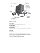
SAVE THIS MANUAL
You will need this manual for the safety warnings and precautions, assembly, oper-
ating, inspection, maintenance and cleaning procedures, parts list and assembly diagram.
Keep your invoice with this manual. Write the invoice number on the inside of the front
cover. Keep this manual and invoice in a safe and dry place for future reference.

For technical questions, please call 1-800-444-3353;
Troubleshooting section at end of manual.
Page 4SKU 95424, 95629
GENERAL SAFETY RULES
WARNING!
READ AND UNDERSTAND ALL INSTRUCTIONS
Failure to follow all instructions listed below may result in
electric shock, fire, and/or serious injury.
SAVE THESE INSTRUCTIONS
WORK AREA
Keep your work area clean and well lit. Cluttered benches and dark areas invite
accidents.
Do not operate power tools in explosive atmospheres, such as in the pres-
ence of flammable liquids, gases, or dust. Power tools create sparks which may
ignite the dust or fumes.
Keep bystanders, children, and visitors away while operating a power tool.
Distractions can cause you to lose control. Protect others in the work area from
debris such as chips and sparks. Provide barriers or shields as needed.
ELECTRICAL SAFETY
Grounded tools must be plugged into an outlet properly installed and grounded
in accordance with all codes and ordinances. Never remove the grounding
prong or modify the plug in any way. Do not use any adapter plugs. Check with
a qualified electrician if you are in doubt as to whether the outlet is properly
grounded. If the tools should electrically malfunction or break down, grounding
provides a low resistance path to carry electricity away from the user.
Avoid body contact with grounded surfaces such as pipes, radiators, ranges,
and refrigerators. There is an increased risk of electric shock if your body is
grounded.
Do not expose power tools to rain or wet conditions. Water entering a power
tool will increase the risk of electric shock.
Do not abuse the Power Cord. Never use the Power Cord to carry the tools or
pull the Plug from an outlet. Keep the Power Cord away from heat, oil, sharp
edges, or moving parts. Replace damaged Power Cords immediately. Dam-
aged Power Cords increase the risk of electric shock.
When operating a power tool outside, use an outdoor extension cord marked
“W-A” or “W”. These extension cords are rated for outdoor use, and reduce the
risk of electric shock.
1.
2.
3.
1.
2.
3.
4.
5.

For technical questions, please call 1-800-444-3353;
Troubleshooting section at end of manual.
Page 5SKU 95424, 95629
PERSONAL SAFETY
Stay alert. Watch what you are doing, and use common sense when operat-
ing a power tool. Do not use a power tool while tired or under the influence
of drugs, alcohol, or medication. A moment of inattention while operating power
tools may result in serious personal injury.
Dress properly. Do not wear loose clothing or jewelry. Contain long hair.
Keep your hair, clothing, and gloves away from moving parts. Loose clothes,
jewelry, or long hair can be caught in moving parts.
Avoid accidental starting. Be sure the Power Switch is off before plugging
in. Carrying power tools with your finger on the Power Switch, or plugging in power
tools with the Power Switch on, invites accidents.
Remove adjusting keys or wrenches before turning the power tool on. A
wrench or a key that is left attached to a rotating part of the power tool may result
in personal injury.
Do not overreach. Keep proper footing and balance at all times. Proper footing
and balance enables better control of the power tool in unexpected situations.
Always wear eye, hearing, and breathing protection. For welding safety equip-
ment, refer to number 9 on page 7.
TOOL USE AND CARE
Use clamps (not included) or other practical ways to secure and support the
workpiece to a stable platform. Holding the work by hand or against your body
is unstable and may lead to loss of control.
Do not force the tool. Use the correct tool for your application. The correct
tool will do the job better and safer at the rate for which it is designed.
Do not use the power tool if the Power Switch does not turn it on or off. Any
tool that cannot be controlled with the Power Switch is dangerous and must be
replaced.
Disconnect the Power Cord Plug from the power source before making any
adjustments, changing accessories, or storing the tool. Such preventive safety
measures reduce the risk of starting the tool accidentally.
Store idle tools out of reach of children and other untrained persons. Tools
are dangerous in the hands of untrained users.
Maintain tools with care. Keep tools in good condition. Properly maintained
tools will get the job done better. Do not use a damaged tool. Tag damaged tools
“Do not use” until repaired.
1.
2.
3.
4.
5.
6.
1.
2.
3.
4.
5.
6.

For technical questions, please call 1-800-444-3353;
Troubleshooting section at end of manual.
Page 6SKU 95424, 95629
Check for misalignment or binding of moving parts, breakage of parts, and any
other condition that may affect the tool’s operation. If damaged, have the tool
serviced before using. Many accidents are caused by poorly maintained tools.
Use only accessories that are recommended by the manufacturer for your
model. Accessories that may be suitable for one tool may become hazardous
when used on another tool.
SERVICE
Tool service must be performed only by qualified repair personnel. Service or
maintenance performed by unqualified personnel could result in a risk of injury.
When servicing a tool, use only identical replacement parts. Follow instruc-
tions in the “Inspection, Maintenance, And Cleaning” section of this manual.
Use of unauthorized parts or failure to follow maintenance instructions may create
a risk of electric shock or injury.
SPECIFIC SAFETY RULES
Ground this product. This Welder requires the attachment and use of a UL-listed,
230 volt, grounded, 3-prong, electrical Power Cord Plug (not included). Only a quali-
fied electrician should install the Power Cord Plug. Never remove the grounding
prong or modify the Power Cord Plug in any way. Do not use adapter plugs with
this product. To comply with the National Electric Code, and to provide additional
protection from the risk of electrical shock, this product should only be connected
to a 230 volt, 3-hole outlet that is properly grounded.
Maintain labels and nameplates on the Welder. These carry important informa-
tion. If unreadable or missing, contact Harbor Freight Tools for a replacement.
Avoid unintentional starting. Make sure you are prepared to begin work before
turning on the Welder.
Never leave the Welder unattended when it is plugged into an electrical outlet.
Turn off the tool, and unplug it from its electrical outlet before leaving.
Industrial applications must follow OSHA guidelines.
Never stand on the Welder. Serious injury could result if the Welder is tipped or
if hot surfaces are accidently contacted.
Maintain a safe working environment. Keep the work area well lit. Make sure
there is adequate surrounding workspace. Always keep the work area free of ob-
structions, grease, oil, trash, and other debris. Do not use a power tool in areas
near flammable chemicals, dusts, and vapors. Do not use this product in a damp
or wet location.
7.
8.
1.
2.
1.
2.
3.
4.
5.
6.
7.

For technical questions, please call 1-800-444-3353;
Troubleshooting section at end of manual.
Page 7SKU 95424, 95629
Prevent eye injury and burns. Wearing and using ANSI-approved
personal safety clothing and safety devices reduce the risk for injury.
Wear ANSI-approved safety impact eye goggles underneath welding eye
protection featuring at least a Number 10 shade lens rating.
Leather leggings, fire resistant shoes or boots should be worn when using this
product. Do not wear pants with cuffs, shirts with open pockets, or any clothing
that can catch and hold molten metal or sparks.
Keep clothing free of grease, oil, solvents, or any flammable substances. Wear
dry, insulating gloves and protective clothing.
Wear an approved head covering to protect the head and neck. Use aprons, cape,
sleeves, shoulder covers, and bibs designed and approved for welding and cut-
ting procedures.
When welding/cutting overhead or in confined spaces, wear flame resistant ear
plugs or ear muffs to keep sparks out of ears.
Prevent accidental fires. Remove any combustible material from the
work area.
When possible, move the work to a location well away from combustible
materials. If relocation is not possible, protect the combustibles with a
cover made of fire resistant material.
Remove or make safe all combustible materials for a radius of 35 feet (10 meters)
around the work area. Use a fire resistant material to cover or block all open
doorways, windows, cracks, and other openings.
Enclose the work area with portable fire resistant screens. Protect combustible
walls, ceilings, floors, etc., from sparks and heat with fire resistant covers.
If working on a metal wall, ceiling, etc., prevent ignition of combustibles on the
other side by moving the combustibles to a safe location. If relocation of combus-
tibles is not possible, designate someone to serve as a fire watch, equipped with
a fire extinguisher, during the cutting process and for at least one half hour after
the cutting is completed.
Do not weld or cut on materials having a combustible coating or combustible in-
ternal structure, as in walls or ceilings, without an approved method for eliminating
the hazard.
Do not dispose of hot slag in containers holding combustible materials. Keep a
fire extinguisher nearby and know how to use it.
After spot welding, make a thorough examination for evidence of fire. Be aware
that easily-visible smoke or flame may not be present for some time after the fire
has started. Do not weld or cut in atmospheres containing dangerously reactive
or flammable gases, vapors, liquids, and dust. Provide adequate ventilation in
work areas to prevent accumulation of flammable gases, vapors, and dust. Do not
apply heat to a container that has held an unknown substance or a combustible
8.
•
•
•
•
•
10.
•
•
•
•
•
•
•

For technical questions, please call 1-800-444-3353;
Troubleshooting section at end of manual.
Page 8SKU 95424, 95629
material whose contents, when heated, can produce flammable or explosive va-
pors. Clean and purge containers before applying heat. Vent closed containers,
including castings, before preheating, welding, or cutting.
Avoid overexposure to fumes and gases. Always keep your head out of the
fumes. Do not breathe the fumes. Use enough ventilation or exhaust, or both, to
keep fumes and gases from your breathing zone and general area.
Where ventilation is questionable, have a qualified technician take an air sam-
pling to determine the need for corrective measures. Use mechanical ventilation
to improve air quality. If engineering controls are not feasible, use an approved
respirator.
Work in a confined area only if it is well ventilated, or while wearing an air-sup-
plied respirator.
Follow OSHA guidelines for Permissible Exposure Limits (PEL’s) for various fumes
and gases.
Follow the American Conference of Governmental Industrial Hygienists recom-
mendations for Threshold Limit Values (TLV’s) for fumes and gases.
Have a recognized specialist in Industrial Hygiene or Environmental Services
check the operation and air quality and make recommendations for the specific
welding or cutting situation.
Inhalation Hazard
Welding Produces TOXIC FUMES and GASSES.
Exposure to welding gasses can increase the risk of developing
certain cancers, such as cancer of the larynx and lung cancer.
Also, some diseases that may be linked to exposure to welding gas-
ses or fumes are:
• Early onset of Parkinson’s Disease • Heart Disease
• Damage to the reproductive organs • Ulcers
• Inflammation of the small intestine or stomach • Kidney damage
• Respiratory diseases such as emphysema, bronchitis or pneumonia
Safety precautions, such as using natural or forced air ventilation and
wearing a NIOSH-approved respirator, are ESSENTIAL to reduce the
risk of developing the above illnesses.
Read and understand all instructions and safety precautions as outlined in
the manufacturer’s manual for the material you will weld or cut.
Do not touch live electrical parts. Wear dry, insulating gloves. Do not touch elec-
trode or conductor tong with bare hand. Do not wear wet or damaged gloves.
11.
•
•
•
•
•
12.
13.

For technical questions, please call 1-800-444-3353;
Troubleshooting section at end of manual.
Page 9SKU 95424, 95629
Protect yourself from electric shock. Do not use outdoors. Insulate yourself from
the workpiece and ground. Use nonflammable, dry insulating material if possible,
or use dry rubber mats, dry wood or plywood, or other dry insulating material big
enough to cover your full area of contact with the work or ground.
Ensure that the unit is placed on a stable location before use. If this unit falls
while plugged in, severe injury, electric shock, or fire may result.
Cylinders can explode when damaged:
Never weld on a pressurized or a closed cylinder.
Never lay a welding torch on a cylinder.
Never allow a welding electrode to touch the cylinder.
Keep cylinders away from any electrical circuits, including welding circuits.
Keep protective cap in place over the valve except when the cylinder is in use.
Use only correct gas shielding equipment designed specifically for the type of
welding you will do. Maintain this equipment properly.
Always protect gas cylinders from heat, being struck, physical damage, slag,
flames, sparks, and arcs.
Always use proper procedures to move cylinders.
Use the right tool for the job. Do not attempt to force small equipment to do the
work of larger industrial equipment. There are certain applications for which this
Welder was designed. It will do the job better and more safely at the rate for which it
was intended. Do not modify this Welder, and do not use this Welder for a purpose
for which it was not intended.
WARNING! People with pacemakers should consult their physician(s) before
using this product. Electromagnetic fields in close proximity to a heart pacemaker
could cause interference to or failure of the pacemaker.
WARNING! The warnings and cautions discussed in this manual cannot cover
all possible conditions and situations that may occur. It must be understood by the
operator that common sense and caution are factors which cannot be built into this
product, but must be supplied by the operator.
WARNING! This product, when used for welding and similar applications, pro-
duces chemicals known to the State of California to cause cancer and birth defects
(or other reproductive harm).
(California Health & Safety Code § 25249.5, et seq.)
SAVE THESE INSTRUCTIONS
14.
15.
16.
•
•
•
•
•
•
•
•
17.
18.
19.
20.

For technical questions, please call 1-800-444-3353;
Troubleshooting section at end of manual.
Page 10SKU 95424, 95629
Grounding
NOTE: This Welder requires the installation of a 3-Prong, 230 VAC, polarized, twistlock
Power Cord Plug
(not included). NEMA configuration # L6-40 or equivalent. The Plug must
be installed by a certified electrician.
WARNING!
Improperly connecting the grounding wire can result in risk of electric shock.
Check with a qualified electrician if you are in doubt as to whether outlet is prop-
erly grounded. Do not modify power cord plug used with tool. Never remove
grounding prong from plug. Do not use tool if the power cord or plug is dam-
aged. If damaged, have it repaired by a service facility before use. If the plug
will not fit the outlet, have a proper outlet installed by a qualified electrician.
GROUNDED TOOLS: TOOLS WITH THREE PRONG PLUGS
Tools marked with “Grounding Required” have a three wire cord and three prong
grounding plug. The plug must be connected to a properly grounded outlet. If the tool
should electrically malfunction or break down, grounding provides a low resistance
path to carry electricity away from the user, reducing the risk of electric shock.
The grounding prong in the plug is connected through the green wire inside the
cord to the grounding system in the tool. The green wire in the cord must be the
only wire connected to the tool’s grounding system and must never be attached to
an electrically “live” terminal.
Your tool must be plugged into an appropriate outlet, properly installed by a certi-
fied electrician and grounded in accordance with all codes and ordinances.
Extension Cords
AN EXTENSION CORD MUST NEVER BE USED WITH THIS ITEM. Use of an
extension cord could result in damage to the item or fire.
Symbology
Double Insulated
Canadian Standards Association
Underwriters Laboratories, Inc.
V~
Volts Alternating Current
A
Amperes
1.
2.
3.

For technical questions, please call 1-800-444-3353;
Troubleshooting section at end of manual.
Page 11SKU 95424, 95629
UNPACKING
When unpacking, make sure all parts shown on the Parts Lists near the end of
this manual are included. If any parts are missing or broken, call Harbor Freight Tools.
ASSEMBLY INSTRUCTIONS
WARNING! Always turn off the Welder and unplug the unit from its electri-
cal outlet prior to performing any assembly, maintenance, or service.
ATTACHING THE WHEELS
Attaching wheels to case can be done for stationary cylinder use or mobile use.
Stationary Mobile
Attach the two Swivel Wheels (27A) at the
front and two Back Wheels (37A) and Axle
(36A) at the Base (28A) of the unit, using the
Clips (38A), Bolts and Washers provided.
(See Assembly Diagram on page 32 and
the following steps.)
Attach the two Swivel Wheels (27A) at front
of the Support (35A), Arm (5A), two Back
Wheels (37A) and Axle (36A) at the rear of
the Base (28A) of the unit, using the Clips
(38A), Bolts and Washers provided. (See
Assy. Diagram on page 32 and the follow-
ing steps.)
For both Stationary and Mobile modes, set the Swivel Wheel (27A) against the front
corner of the case, making sure to align the holes. Screw the Bolts through the
Washers and into the Case. (See Figures 1.)
1.

For technical questions, please call 1-800-444-3353;
Troubleshooting section at end of manual.
Page 12SKU 95424, 95629
ASSEMBLY INSTRUCTIONS (CONTINUED)
Stationary
Mobile
Set the Axle (36A) with the Back Wheels
(37A) attached against the bottom of the
case. Then, screw the Bolts through the
Washers and into the bottom of the case.
(See Figure 4, above left.)
Set Arm (5A) against the top back of the
welder case. Screw the Bolts through
Washers and into the welder case.
(See Figure 4, above right.)
Set the Support (35A) against the bot-
tom back of the case. Align the holes and
screw the Bolts through the Washers and
into the case.
Set the Axle (36A) with the Back Wheels
(37A) against the bottom of the Support
(35A). Screw the Bolts through the Wash-
ers and into the Support.
Install the Back Wheels (37A) at the Axle (36A). Install the Back Wheels (37A) at the Axle (36A).
2. 2.
3.
Fix the Back Wheels(37A) with the
Clips (38A).
3.
Fix the Back Wheels (37A) with the
Clips (38A).
4.
4.
Arm (5A)
Washer and Bolt

For technical questions, please call 1-800-444-3353;
Troubleshooting section at end of manual.
Page 13SKU 95424, 95629
INSTALLING A WIRE SPOOL
Assembling the Wire Spool depends on whether you are using a 7” Spool or an 11”
Spool.
For use with a 7” Spool:
MIG&ARC 250 AMP - SKU 95424
MIG DUAL 250 AMP – SKU
For technical questions, please call 1-800-444-3353;
Troubleshooting section at end of manual.
Page 14
TO INSTALL THE WIRE SPOOL
Two variants to expose the Wire Drive Assembly are probable for Spool 200mm (variant A)
and for EN 759 Spool 300mm (variant B) use.
Variant A
1.
Lift the Door (14A) of the Welder to expose
the Wire Drive Assembly.
2.
Insert the Spool and the Pressing Cartridge
onto the Threaded Shaft (11A). Making
sure the Spool's Welding Wire unwinds
from the bottom (clockwise).
3.
When a slight force is needed to turn Spool,
tension is set.
4.
Screw the Fixing Cover into the Threaded
Shaft (11A).
Variant B
1.
Lift the Door (14A) of the Welder to expose
the Wire Drive Assembly.
2.
Insert the Spool′s Holder onto the
Threaded Shaft (11A).
For use with a 11” Spool:
MIG&ARC 250 AMP - SKU 95424
MIG DUAL 250 AMP – SKU
For technical questions, please call 1-800-444-3353;
Troubleshooting section at end of manual.
Page 14
TO INSTALL THE WIRE SPOOL
Two variants to expose the Wire Drive Assembly are probable for Spool 200mm (variant A)
and for EN 759 Spool 300mm (variant B) use.
Variant A
1.
Lift the Door (14A) of the Welder to expose
the Wire Drive Assembly.
2.
Insert the Spool and the Pressing Cartridge
onto the Threaded Shaft (11A). Making
sure the Spool's Welding Wire unwinds
from the bottom (clockwise).
3.
When a slight force is needed to turn Spool,
tension is set.
4.
Screw the Fixing Cover into the Threaded
Shaft (11A).
Variant B
1.
Lift the Door (14A) of the Welder to expose
the Wire Drive Assembly.
2.
Insert the Spool′s Holder onto the
Threaded Shaft (11A).
ASSEMBLY INSTRUCTIONS (CONTINUED)

For technical questions, please call 1-800-444-3353;
Troubleshooting section at end of manual.
Page 14SKU 95424, 95629
ROUTING THE WIRE
Note: When installing wire of different size or composition, you will also need to change
wire settings, set gun polarity, and, possibly, install gas cylinder. (See pages 18
to 20.)
Welding Wire Spool
Figure A
IMPORTANT: Securely hold onto the end of the Welding Wire and keep tension on it
during the following steps. If this is not done the Welding Wire will spring backward,
creating a tangled “bird’s nest” and resulting in wasted wire. (See Figure A.)
Hold the Welding Wire securely while you cut enough Wire off the end of the
Spool to remove all bent and crimped Wire. Make sure the cut end has no burrs
or sharp edges (cut again, if needed). (See Figure A.)
1.
2.
ASSEMBLY INSTRUCTIONS (CONTINUED)
3.
Insert the Spool onto the Spool′s Holder.
Making sure the Spool's Welding Wire
unwinds from the bottom
(clockwise).
4.
5.
Screw the Fixing Cover into the Threaded Shaft (11A).
Attach a Spool with the help of latch.

For technical questions, please call 1-800-444-3353;
Troubleshooting section at end of manual.
Page 15SKU 95424, 95629
ASSEMBLY INSTRUCTIONS (CONTINUED)
3. Loosen, and lower the Handle (4D) on the Wire Drive Assembly. Then, raise the
Lever (3D). (See Figure B)
4. Keep tension on the Wire, and guide at least 12 inches of Wire into the Wire Inlet
Guide. (See Figure C)
5. Lower the Lever (3D) on the Wire Drive Assembly. Raise and tighten the
Handle (4D). Once the Wire is held in place, you may release it. (See Figure D)
Handle
Lever
FIGURE B
Wire Inlet Guide
Welding Wire
FIGURE C
Handle Welding Wire
Lever
FIGURE D
Loosen and lower the Tension Adjusting Knob on the Wire Feed Assembly. Then,
raise the Swing Arm. (See Figure B.)
MIG&ARC 250 AMP - SKU 95424
MIG DUAL 250 AMP – SKU
For technical questions, please call 1-800-444-3353;
Troubleshooting section at end of manual.
Page 16
3. Loosen, and lower the Handle (4D) on the Wire Drive Assembly. Then, raise the
Lever (3D). (See Figure B)
4. Keep tension on the Wire, and guide at least 12 inches of Wire into the Wire Inlet
Guide. (See Figure C)
5. Lower the Lever (3D) on the Wire Drive Assembly. Raise and tighten the
Handle (4D). Once the Wire is held in place, you may release it. (See Figure D)
Handle (4D)
Lever (3D)
FIGURE B
Wire Inlet Guide
Welding Wire
FIGURE C
Handle (4D) Welding Wire
Lever (3D)
FIGURE D
Keep tension on the Welding Wire, and guide at least 12 inches of Wire into the
Wire Feed Leader. (See Figure C.)
3. Loosen, and lower the Handle (4D) on the Wire Drive Assembly. Then, raise the
Lever (3D). (See Figure B)
4. Keep tension on the Wire, and guide at least 12 inches of Wire into the Wire Inlet
Guide. (See Figure C)
5. Lower the Lever (3D) on the Wire Drive Assembly. Raise and tighten the
Handle (4D). Once the Wire is held in place, you may release it. (See Figure D)
Handle
Lever
FIGURE B
Wire Inlet Guide
Welding Wire
FIGURE C
Handle Welding Wire
Lever
FIGURE D
Lower the Level on the Wire Drive Assembly. Raise and tighten the Handle. Once
the Wire is held in place, you may release it. (See Figure D.)
3.
4.
5.

For technical questions, please call 1-800-444-3353;
Troubleshooting section at end of manual.
Page 16SKU 95424, 95629
Lay Torch Cable out in a straight line so Welding Wire moves through it easily.
Leave Door (14A) of the Welder open so Wire Feed Assembly can be observed.
Remove the Gun Nozzle (1E) and Contact Tip (2E). (See Figure E.)
6.
7.
ASSEMBLY INSTRUCTIONS (CONTINUED)
WARNING!
EXERCISE EXTREME CAUTION - RISK OF FIRE AND/OR ELECTRIC SHOCK!
The following steps require powering the Welder. Do not touch
anything with Torch Handle or Welding Wire or an arc will be ignited.
Do not touch internal components of while unit is plugged in.
After having certified electrician install power cord plug, insert the Power Cord
(1A) into its 230 volt, grounded, electrical outlet. Turn Power Switch (1C) to
ON.
Point Torch Handle away from all objects. Squeeze Trigger Switch (13E) on Torch
Handle until Welding Wire feeds through the Head Tube (4E) of the Torch Handle
about 2 inches. If necessary, move the Torch Handle slightly in a circular motion
to help feed the Welding Wire properly out of the Head Tube. (See Figure E.)
NOTE: If the Welding Wire does not feed properly, and the Spool is stationary,
turn the Welder OFF. Unplug the Welder. Slightly tighten the Handle (4D) on the
Wire Feed Assembly. (See Figure D.)
To check the tension on the Wire Feed Assembly, feed the Welding Wire against
a piece of scrap wood from 2 to 3 inches away. If the Wire stops instead of bend-
ing, turn the Welder OFF. Unplug the unit from its electrical outlet. Then, slightly
tighten the Handle (4D) on the Wire Feed Assembly.
Reminder: When installing wire of a different size or composition, you will also
need to change wire settings, set the gun polarity, and possibly install a gas cyl-
inder.
8.
9.
10.
11.
HEAD TUBE (4E)
CONTACT TIP (2E)
CONTACT TIP (2E)
HEAD
TUBE (4E)
NOZZLE (1E)
NOZZLE (1E)
WELDING WIRE
TRIGGER SWITCH
(13E)
TRIGGER SWITCH
(13E)
FIGURE E
Turn the Welder OFF, unplug it, and discharge the electrode to ground. Insert the
Contact Tip (2E) onto the Welding Wire and screw it firmly into the Head Tube (4E)
of the Torch Handle. Replace the Nozzle (1E), and cut off any excess Welding Wire
over 1/2 inch. Then, close the Access Panel of the Welder. (See Figure E.)
12.

For technical questions, please call 1-800-444-3353;
Troubleshooting section at end of manual.
Page 17SKU 95424, 95629
CHANGING WIRE SETTINGS
WARNING! Make sure to turn off the Welder and unplug it from its electrical
outlet prior to changing wire settings.
Lift the Door (14A) of the Welder to expose the Wire Feed Assembly.
Loosen, and lower the Handle (4D) on the Wire Feed Assembly.
Remove the Screw that secures the Roller (5D) in place. Then remove the two
Rollers.
MIG&ARC 250 AMP - SKU 95424
MIG DUAL 250 AMP – SKU
For technical questions, please call 1-800-444-3353;
Troubleshooting section at end of manual.
Page 18
TO CHANGE WIRE SETTINGS
. WARNING! Make sure to turn off the Welder and unplug it from its electrical outlet
prior to changing wire settings.
1. Lift the Door (14A) of the Welder to expose the Wire Drive Assembly.
2. Loosen, and lower the Handle (4D) on the Wire Drive Assembly.
3. Remove the Screw that secures the Roller (5D) in place. Then, remove the two Rollers.
4. Flip each Roller 180 degrees. (See Figure F)
NOTE: The two Rollers are “keyed”, meaning they can only be reinstalled one way.
5. Reinstall the two Rollers, and secure the Rollers in place with the Screw. (See Figure F)
6. Install the Spool of Welding Wire, and route the Wire to the Torch Gun. Then, test and, if
necessary, adjust the Wire Drive Assembly as discussed in the previous pages of this
manual.
TO ATTACH THE GROUND CABLE WITH CLAMP
Insert the Connecting Plug of the Ground Cable (22A) into the Terminal Ground (7C) and
twist the Connecting Plug to lock it in place. (See Part List page 34)
.
TO ATTACH THE ELECTRODE CABLE
(Only MIG/ ARC 250 AMP)
Insert the Connecting Plug of the Electrode Cable (21A) into the Terminal Electrode (6C)
and twist the Connecting Plug to lock it in place. (See Part List page 34)
WELDING WIRE
ROLLERS
(
5
D
)
FLIP 180
°
°°
°
FIGURE F
Flip each Roller 180 degrees. (See Figure F.)
Note: The two Rollers are “keyed”, which means they can only be reinstalled one
way.
Reinstall the two Rollers and secure the Rollers in place with the Screw.
(See Figure F.)
Install the Spool of Welding Wire and route the Wire to the Torch Gun. Then, test
and, if necessary, adjust the Wire Feed Assembly as discussed in the previous
pages of this manual.
ATTACHING THE GROUND CABLE WITH CLAMP
Insert the Connecting Plug to the Ground Cable (22A) into the Terminal Ground (7C)
and twist the Connecting Plug to lock in place. (See Parts List on Page 31).
ATTACHING THE ELECTRODE CABLE (ARC WELDER ONLY)
Insert the Connecting Plug to the Ground Cable (22A) into the Terminal Electrode
(6C) and twist the Connecting Plug to lock in place. (See Parts List on Page 31).
1.
2.
3.
4.
5.
6.
7.

For technical questions, please call 1-800-444-3353;
Troubleshooting section at end of manual.
Page 18SKU 95424, 95629
SETTING POLARITY FOR WELDING TYPE
WARNING! Always turn welder off and disconnect it from it’s electrical supply before
opening the case or performing any adjustment, including the following pro-
cedure.
Set for Electrode Positive (DCEP) for gas
welding with solid-core wire
- Red electrode cable (C) to positive termi-
nal (A);
- Black ground cable (D) to negative termi-
nal (B).
SEE ILLUSTRATION, TOP RIGHT INITIAL
SETUP.
To reverse polarity
1. Remove the nuts.
2. Change the places of the cables (C, D).
3. Replace and tighten the nuts.
When connecting the weld output terminals,
you should keep the square washers in
place.
Set for Electrode Negative (DCEN) for
gasless flux core wire:
- Red electrode cable (C) to negative termi-
nal (B);.
- Black ground cable (D) to positive terminal
(A).
(See illustration, bottom right.)
Always read and follow wire manufacturer’s
recommended polarity.
1.
2.
3.
4.
MIG&ARC 250 AMP - SKU 95424
MIG DUAL 250 AMP – SKU
For technical questions, please call 1-800-444-3353;
Troubleshooting section at end of manual.
Page 19
SETTING THE GUN & ELECTRODE POLARITY FOR WELDING TYPE
1.Set for Electrode Positive (DCEP)
for gas welding with solid-core wire:
-Red Electrode Cable (C) to Positive Terminal (A);
-Black Ground Cable (D) to Negative Terminal (B).
SHOWN IN ILLUSTRATION, INITIAL SETUP.
2. SETTING
1.Turn off the nuts.
2. Change by places of the connecting plugs.
3.Strongly twirl the nuts.
When connecting to the weld output terminals, it
is necessary to save the square washers.
3. Set for Electrode Negative (DCEN)
for gas-less flux core wire:
-Red Electrode Cable (C) to Negative Terminal (B);
-Black Ground Cable (D) to Positive Terminal (A).
4. Always read and follow wire manufacturer’s rec-
ommended polarity.
A. Positive (+) Output Terminal
B. Negative (–) Output Terminal
C. Red Cable - Electrode
D. Black Cable - Ground
Positive (+) Output Terminal
Negative (–) Output Terminal
Red Cable - Electrode
Black Cable - Ground
A.
B.
C.
D.
DCEP
DCEN

For technical questions, please call 1-800-444-3353;
Troubleshooting section at end of manual.
Page 19SKU 95424, 95629
INSTALLING A GAS CYLINDER
WARNING: Using an oversized gas cylinder can cause tipping, result-
ing in cylinder and equipment damage and personal injury. NEVER exceed
maximum cylinder weight of 100 lb.
CAUTION! Do not use an Argon/Mixed pressure regulator/flow meter with CO
2
shielding gas. To use CO
2
shielding gas, you must install a CO
2
gas pressure
regulator/flow meter (neither one included).
MIG&ARC 250 AMP - SKU 95424
MIG DUAL 250 AMP – SKU
For technical questions, please call 1-800-444-3353;
Troubleshooting section at end of manual.
Page 20
TO INSTALL A GAS CYLINDER
1. CAUTION! Do not use an Argon/Mixed pressure regulator/flow meter with CO
2
shielding gas. To use CO
2
shielding gas, you must install a CO
2
gas pressure regula-
tor/flow meter (neither one included).
2. USING AN OVERSIZED GAS CYLINDER CAN CAUSE TIPPING resulting in cylin-
der and equipment damage and personal injury. Do not exceed maximum cylinder
weight of 100 lbs. (45 kg).
3. With assistance, set the cylinder upright against a solid post or other stationary object
and use a chain or a heavy duty strap (neither included) to secure the cylinder in place.
(See Figure G)
4. Remove the protective cap from the cylinder. Stand to the side of the cylinder valve, and
open the valve slightly to blow dust and dirt from the valve. Then, close the valve. (See
Figure G)
5. Make sure the Flow Adjust on the Pressure Regulator/Flow Meter is turned off. Then,
screw the Pressure Regulator/Flow Meter firmly onto the cylinder valve. (See Figure G)
6. Attach the Gas Hose from the Pressure Regulator/Flow Meter to the Gas Inlet Valve lo-
cated on the Rear Panel of the Welder. (See Figure G)
7. Adjust the flow rate of the gas by turning the Flow Adjust. The typical flow rate is 20 cfh
(cubic feet per hour). Make sure to check the Welding Wire manufacturer’s recom-
mended flow rate. (See Figure G)
1.
Cap.
2.
Cylinder Valve.
Remove Cap, stand to side of valve
slightly. Gas flow blows dust and dirt
from valve. Close valve.
3.
Cylinder.
4.
Regulator/ Flowmeter
Install so face is vertical.
5.
Regulator/Flowmeter Gas.
6.
Hose Connection.
Connect customer supplied gas hose
between regulator/flowmeter hose con-
nection, and fitting of welder.
7.
Flow Adjust.
8.
Solid post or other stationary object.
9.
Chain or strap.
FIGURE G
With help, set cylinder (not included) upright against post or other stationary ob-
ject. Use chain or heavy-duty strap (neither included) to secure cylinder in place.
(See Figure G.)
Remove the protective cap from the cylinder. Stand to the side of the cylinder
valve, and open the valve slightly to blow dust and dirt from the valve. Then,
close the valve. (See Figure G.)
Make sure the Flow Adjust on the Pressure Regulator/Flow Meter is turned off.
Then, screw the Pressure Regulator/Flow Meter (not included) firmly onto the
cylinder valve. (See Figure G.)
Attach the Gas Hose for the Pressure Regulator/Flow Meter to the Gas Inlet
Valve located on the Rear Panel of the Welder. (See Figure G.)
Adjust the flow rate of the gas by turning the Flow Adjust. The typical flow rate is 20
CFH (cubic feet per hour). Make sure to check the Welding Wire manufacturer’s
recommended flow rate.
1.
2.
3.
4.
5.
6.

For technical questions, please call 1-800-444-3353;
Troubleshooting section at end of manual.
Page 20SKU 95424, 95629
OPERATING INSTRUCTIONS
BEFORE YOU BEGIN WELDING
Good welding requires a high degree of skill and experience. You should practice
a few sample welds on scrap metal before you begin welding your first project. Ad-
ditional practice periods are recommended whenever you weld a different thickness
of material, wire, or weld a different type of connection.
UNDERSTANDING DUTY CYCLE (DURATION OF USE)
CAUTION! Avoid damage to the Welder by not leaving the unit on for more than
the prescribed duty cycle time.
100% Duration of use
at 125 Amp Setting
Continuous
use
30% Duration of use
at 250 Amp Setting
3 minutes in use
followed by
at least
7 minutes OFF
in a single 10 minute period
Other settings fall between these two ranges.
FIGURE H
The duty cycle defines the number of minutes, within a 10 minute period, during
which a given Welder can safely produce a particular welding current. For example,
this Welder, with a 30% duty cycle at 250 Amps must be allowed to rest for at
least 7 minutes after every 3 minutes of continuous weld at 250 Amps. (See
Figure H.)
Failure to carefully observe duty cycle limitations can easily over-stress a Welder’s
power generation system, contributing to premature Welder failure.
This Welder is equipped with an internal thermal protection system to help prevent
over stressing the unit. When the unit overheats, it automatically shuts down, then
automatically returns to service when it cools down.
Note: Once the unit returns to service, follow a more conservative duty cycle routine to
help prevent excess wear to the Welder. (See Figure H.)
1.
2.
3.
4.
/