INDOOR TRAINING BIKE
Item #1220
OWNER’S
MANUAL

SERVICE ------------------------------------------------------------------------ 2
WARNING LABEL PLACEMENT ------------------------------------------ 3
PRODUCT SAFETY ---------------------------------------------------------- 4
OVERVIEW DRAWING ------------------------------------------------------- 5
PART LIST ----------------------------------------------------------------------- 6
HARDWARE PACKING LIST & TOOLS --------------------------------- 8
ASSEMBLY --------------------------------------------------------------------- 9
COMPUTER --------------------------------------------------------------------- 15
ADJUSTMENTS ---------------------------------------------------------------- 16
EMERGENCY STOP ---------------------------------------------------------- 18
MOVING THE BIKE ----------------------------------------------------------- 19
TROUBLE SHOOTING & MAINTENANCE ----------------------------- 20
WARM UP ----------------------------------------------------------------------- 21
WARRANTY -------------------------------------------------------------------- 22
FAX FORM ---------------------------------------------------------------------- 23
TABLE OF CONTENTS
1

IMPORTANT: FOR NORTH AMERICA ONLY
To request product service and order
replacement parts, please call our
customer service department at:
1-866-924-1688
Monday through Friday, 8:00 AM-5:00 PM Pacific Standard Time,
or email us at: service@paradigmhw.com
Please visit our website at www.paradigmhw.com.
Please have the following information ready when requesting for service:
Your name
Phone number
Model number
Serial number
Part number
Proof of Purchase
*Before returning this product to the store please contact
customer service at the contact number.
Paradigm Health & Wellness, Inc.
1189 Jellick Ave, City of Industry, CA 91748, USA
SERVICE
2

3
WARNING LABEL PLACEMENT

Basic precautions should always be followed, including the following safety
instructions when using this equipment: Read all instructions before using
this equipment.
1. Read all the instructions in this manual and do warm up exercises before using
this equipment.
2. Before exercise, in order to avoid injuring your muscles, warm-up exercise
for every muscle group is highly recommended. Please refer to the Warm
Up pages for pre and post workout.
3. Please make sure all components are not damaged and in working order before
use. This equipment should be placed on a flat surface while in use. Using a
mat or other material on the ground is recommended.
4. Please wear proper clothes and shoes when using this equipment; do not wear
clothes that get caught in any part of the equipment.
5. Do not attempt any maintenance or adjustments other than those described in
this manual. Should any problems arise, discontinue use and consult an
Authorized Service Representative.
6. Keep Dry - do not operate in wet or moist condition.
7. Always hold on to the handlebar while using the training bike.
8. To dismount, reduce pedaling speed gradually before you stop.
9. Do not use the equipment outdoors.
10. This equipment is for household use only.
11. Only one person should be on the equipment while in use.
12. Keep children and pets away from the product while in use. This machine
is designed for adults only. This product requires a minimum of 6 feet of
space for safe operation.
13. If you feel any chest pains, nausea, dizziness, or short of breath, you should
stop exercising immediately and consult your physician before continuing.
14. The maximum weight capacity for this product is 300 lbs/136 kgs.
WARNING: Before beginning any exercise program consult your
physician. This is especially important for the people who are over 35 years
old or who have pre-existing health problems. Read all instructions before
using any fitness equipment.
CAUTION: Read all instructions carefully before operating this
product. Retain this Owner’s Manual for future reference.
PRODUCT SAFETY
4

PART DRAWING
5

No.
Description
Qty
No.
Description
Qty
001
Main Frame 1006x150x766
1
029
Crank Cover Ø22
2
002
Front Stabilizer 500x97x70
1
030
Pan Head Phillips Self Drilling
Screw ST4.2x13
5
003
Rear Stabilizer 500x60x70
1
031
Bolt M6x12
4
004
Seat Post 456x203x30
1
032
Big Washer Ø6.5xØ16x1.2
2
005
Seat Sliding Tube 361x23.5x149
1
033
Screw ST4.2x23
2
006
Handlebar Post 364x60x114
1
034
Screw ST3.8x9
2
007
Hand Pulse Handlebar
380x512x80
1
035
Screw ST4.2x19
4
008
Small Handlebar 260x468x103
1
036
Bottle Holder Ø88x134
1
009
Small Handlebar Connector
67x45x35
1
037
Round Knob M16x1.5
3
010
Flywheel (Ø460) (40 lbs/18 kgs)
1
038
Plastic Bushing
2
011
Outer Cover 651x265x40.5
1
039
Seat Post Plastic Bushing
2
012
Inner Cover 452x262x33
1
040
Rectangular End Cap
53.5x23.5x1.5
4
013
Rectangular Cover Plate 108x22
1
041
Seat Cushion DD-6619
1
014
Right Foot Pedal 9/16"
1
042
Nut M8
2
015
Left Foot Pedal 9/16"
1
043
Bolt M8x40
2
016
Right Crank 170x43,9/16"
1
044
Transport Wheel Ø42xØ8.3x22
2
017
Left Crank 170x43,9/16"
1
045
Nylon Nut M8
2
018
Front Stabilizer End Cap Ø60
4
046
Cap Nut M12x1
2
019
Adjustable Leveler
Ø42xM12x1.75
4
047
Eyebolt M6x66
2
020
Bolt M8x72
4
048
Nut M6
4
021
Curve Washer Ø8
6
049
Washer Ø20xØ13x6
2
022
Cap Nut M8
4
050
Nut M12x1
2
023
Chain Wheel 215x175
1
051
Flywheel Washer Ø17xØ12.2x2.5
2
024
Sleeve Ø22xØ18x4.5
1
052
Flywheel Axle Ø12x150
1
025
Bearing (6203ZZ)
2
053
Bearing (6001ZZ)
2
026
C Ring Ø17
1
054
Lock Nut Ø42x5.5,M33x1
2
027
Protection Cover
1
055
Small Chain Wheel
1
028
Nut 3/8"
2
056
Flywheel Sleeve Ø16xØ12x13
1
PART LIST
6

No.
Description
Qty
No.
Description
Qty
057
Wire Grommet Ø12
4
073
Handlebar Foam Grip
Ø30xØ37x760
1
058
Brake Knob Ø44x48.5,M8
1
074
Handlebar End Cap Ø32x1.5
2
059
Spring Ø1
1
075
Computer LT8817
1
060
Brake Knob Rod Ø10x150
1
076
Bolt M8x15
4
061
Decoration Cover for Brake
1
077
Spring Washer Ø8
6
062
Square Nut 15x15x10,M10
1
078
Washer Ø8
4
063
Cap Nut Ø15x16
1
079
Computer Bracket
1
064
Sensor Bracket 22x14
1
080
Chain
1
065
End Cap 60x30x1.5
1
081
Hand Pulse Sensor
2
066
Lock Knob M16x1.5
1
082
Hand Pulse Sensor Wire L=650mm
1
067
Spring Plate δ1
1
083
Sensor with Wire L=250mm
1
068
Brake Bracket 120x30x35
1
084
Bolt M8x45
2
069
Bolt M6x8
2
085
Small Magnet Ø15x7
1
070
Nylon Nut M5
2
086
Brake Pad 115x25x6
1
071
Handlebar Foam Grip
Ø30xØ37x250
2
087
Bolt M5x30
2
072
Handlebar Foam Grip
Ø30xØ37x200
2
7
PART LIST

HARDWARE PACKING LIST & TOOLS
8
(20) Bolt M8x72 4 PCS
(21) Curve Washer Ø8 4 PCS
(22) Cap Nut M8 4 PCS
Double Open End Wrench #13, #15
1 PC
Allen Wrench #6
1 PC
(21) Curve Washer Ø8
2 PCS
(77) Spring Washer Ø8
2 PCS
(84) Bolt M8x45
2 PCS
(76) Bolt M8x15
4 PCS
(77) Spring Washer Ø8
4 PCS
(78) Washer Ø8
4 PCS
Double Open End Wrench #13, #17
1 PC

1. Front/Rear Stabilizers and Right/Left Foot Pedals Installation
Position the Front Stabilizer (2) in front of the Main Frame (1) and align bolt holes.
Attach the Front Stabilizer (2) onto the front curve of the Main Frame (1) with two M8x72
Bolts (20), two Ø8 Curve Washers (21), and two M8 Cap Nuts (22). Tighten cap nuts
with the #13, #15 Double Open End Wrench provided.
Position the Rear Stabilizer (3) behind the Main Frame (1) and align bolt holes.
Attach the Rear Stabilizer (3) onto the rear curve of the Main Frame (1) with two M8x72
Bolts (20), two Ø8 Curve Washers (21), and two M8 Cap Nuts (22). Tighten cap nuts
with the #13, #15 Double Open End Wrench provided.
Foot Pedals Installation
The Cranks, Pedal Shafts, and Foot Pedals are marked “R” for Right and “L” for
Left.
Insert the pedal shaft of Left Foot Pedal (15) into threaded hole in the Left Crank (17).
Turn the pedal shaft by hand in the counter-clockwise direction until snug.
Note: DO NOT turn the pedal shaft in the clockwise direction, doing so will strip
the threads.
Tighten the pedal shaft of Left Foot Pedal (15) with the #13, #15 Double Open End
Wrench provided.
Insert pedal shaft of Right Foot Pedal (14) into threaded hole in Right Crank (16). Turn
ASSEMBLY
9
Important:
Please make sure the right foot
pedal matches up with the right
crank and the left foot pedal
matches up with the left crank.
If reversed the cranks may
become damaged or stripped.
Important:
Screw Right Foot Pedal
(14) into right crank
clockwise!
Screw Left Foot Pedal (15)
into Left crank
counter-clockwise!
!
Double Open End Wrench #13, #15
Tool:

the pedal shaft by hand in the clockwise direction until snug. Tighten pedal shaft of
Right Foot Pedal (14) with the #13, #15 Double Open End Wrench provided.
Hardware:
(20) Bolt M8x72 4 PCS
(21) Curve Washer Ø8 4 PCS
(22) Cap Nut M8 4 PCS
ASSEMBLY
10

2. Seat Post, Seat Sliding Tube, Seat Cushion, and Handlebar Post Installation
Turn the Round Knob (37) on the Main Frame (1) in a counterclockwise direction until it
can be pulled out. Pull out the Round Knob (37) and then insert the Seat Post (4) into
the Plastic Bushing (38) on the tube of the Main Frame (1). Slide the Seat Post (4) up
or down direction to the suitable position. Lock the Seat Post (4) in place by releasing
the Round Knob (37) and sliding the Seat Post (4) up or down slightly until the Round
Knob (37) "pops" down into the locked position. For added safety, tighten the Round
Knob (37) in a clockwise direction.
NOTE: When adjusting the height of seat post, the MAX line cannot be higher than
the edge of plastic bushing.
Insert the Seat Sliding Tube (5) into the Seat Post Plastic Bushing (39) on the tube of
the Seat Post (4) and then attach the Round Knob (37) onto the tube of the Seat Post (4)
by turning it in a clockwise direction with the #13, #17 Double Open End Wrench
provided to lock the Seat Sliding Tube (5) in the suitable position.
Loosen both M8 Nuts (42) from underside of the Seat Cushion (41) with the #13, #17
Double Open End Wrench provided. Then install the Seat Cushion (41) onto the Seat
ASSEMBLY
Double Open End Wrench #13, #17
Tool:
11

Sliding Tube (5) and secure with both M8 Nuts (42) that were loosened. Tighten both
M8 Nuts (42) with the #13, #17 Double Open End Wrench provided.
Insert the Handlebar Post (6) into the Plastic Bushing (38) on the tube of the Main
Frame (1) and then attach the Round Knob (37) onto the tube of the Main Frame (1) by
turning it in a clockwise direction with the #13, #17 Double Open End Wrench provided
to lock the Handlebar Post (6) in the suitable position.
NOTE: When adjusting the height of handlebar post, the MAX line cannot be
higher than the edge of plastic bushing.
Finally, attach the Lock Knob (66) onto the tube of the Main Frame (1) by turning it in a
clockwise direction to lock the Handlebar Post (6) in place.
.
12
ASSEMBLY

3. Hand Pulse Handlebar, Small Handlebar, Computer Bracket, and Computer
Installation
Attach the Small Handlebar (8) and Small Handlebar Connector (9) onto the Hand
Pulse Handlebar (7) with two Ø8 Curve Washers (21), two Ø8 Spring Washers (77),
and two M8x45 Bolts (84). Tighten bolts with the #6 Allen Wrench provided.
Attach the Hand Pulse Handlebar (7) with Computer Bracket (79) onto the Handlebar
Post (6) with four M8x15 Bolts (76), four Ø8 Spring Washers (77), and four Ø8
Washers (78). Tighten bolts with the #6 Allen Wrench provided.
Slide the Computer (75) onto the Computer Bracket (79) until it locks into place.
Hardware:
ASSEMBLY
13
Allen Wrench #6
Tool:
(21) Curve Washer Ø8
2 PCS
(77) Spring Washer Ø8
2 PCS
(84) Bolt M8x45
2 PCS
(76) Bolt M8x15
4 PCS
(77) Spring Washer Ø8
4 PCS
(78) Washer Ø8
4 PCS

4. Connecting the Wires
Connect the Sensor Wire (83) to the wire that comes from the Computer (75).
Plug the Hand Pulse Sensor Wire (82) into the receptacle located on the back of the
Computer (75).
14
ASSEMBLY

USING YOUR COMPUTER
The computer can be activated by pressing the button or by pedaling. If you leave the
computer idle for 4 minutes, the power will shut off automatically.
BUTTON FUNCTIONS:
MODE: Press the MODE button to select each function of the computer.
Press and hold the MODE button for 4 seconds to reset all data values to zero.
COMPUTER FUNCTIONS:
SCAN: Press the MODE button until the “►” points to SCAN, the computer will
automatically scan each function in sequence with change every 4 seconds.
TIME: Press the MODE button until the “►” points to TIME, the computer will display
your elapsed workout time in minutes and seconds.
SPD (SPEED): Press the MODE button until the “►” points to SPD (SPEED), the
computer will display the current training speed.
DIST (DISTANCE): Press the MODE button until the “►” points to DIST (DISTANCE),
the computer will display the accumulative distance traveled during workout.
CAL (CALORIES): Press the MODE button until the “►” points to CAL (CALORIES),
the computer will display the total accumulated calories burned during workout.
RPM: Press the MODE button until the “►” points to RPM, the computer will display
the revolutions per minute.
PULSE: Press the MODE button until the “►” points to PULSE, the computer will
display your current heart rate figures after you grip the handlebar sensors with both
your hands during exercise. To ensure the pulse readout is more precise, please
always hold on to the handlebar grip sensors with two hands instead of just with one
hand only when you try to test your heart rate figures.
COMPUTER
15

Brake Knob
HOW TO INSTALL THE BATTERIES:
1. Remove the battery cover on the back of the computer.
2. Place two "SIZE-AA" batteries into the battery housing.
3. Insure batteries are correctly positioned and battery springs are in proper contact
with batteries.
4. Re-install the battery cover.
5. If the display is illegible or only partial segment appear, remove batteries and wait
15 seconds before reinstalling.
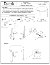
ADJUSTMENTS
Adjusting the Adjustable Leveler
Turn the Adjustable Leveler on the front and rear stabilizers as needed to level the bike.
Adjusting the Brake Knob
To increase the tension, turn the Brake Knob in a clockwise direction.
To decrease the tension, turn the Brake Knob in a counterclockwise direction.
ADJUSTMENTS
16
Adjustable Leveler

Round Knob
Lock Knob
Adjusting the Handlebar Height
Loosen the Lock Knob and then loosen the Round Knob by turning counterclockwise
direction until it can be pulled out. Pull out the Round Knob and then slide the
Handlebar Post up or down direction to the suitable position. Lock the Handlebar Post
in place by releasing the Round Knob and sliding the Handlebar Post up or down slightly
until the Round Knob "pops" down into the locked position. For added safety, tighten
both Lock Knob and Round Knob in a clockwise direction.
NOTE: When adjusting the height of handlebar post, the MAX line cannot higher
than the edge of plastic bushing.
Adjusting the Seat Height
Loosen the Round Knob by turning counterclockwise direction until it can be pulled out.
Pull out the Round Knob and then slide the Seat Post up or down direction to the suitable
position. Lock the Seat Post in place by releasing the Round Knob and sliding the Seat
Post up or down slightly until the Round Knob "pops" down into the locked position. For
added safety, tighten the Round Knob in a clockwise direction.
NOTE: When adjusting the height of seat post, the MAX line cannot higher than
the edge of plastic bushing.
ADJUSTMENTS
17
Round Knob

Adjusting the Seat Forward or Back
Loosen the Round Knob by turning it in a counterclockwise direction. Slide the Seat
Sliding Tube in a forward direction to the suitable position. Lock the Seat Sliding Tube
in place by turning it in a clockwise direction.
EMERGENCY STOP
To emergency stop, press firmly down onto the BRAKE KNOB. Continue holding the
BRAKE KNOB down until the flywheel comes to a complete stop.
Round Knob
EMERGENCY STOP
18

Start by carefully pushing down on the handlebar until the rear end of the bike lifts in
the air. Carefully push the bike to the desired location.
19
MOVING THE BIKE
Page is loading ...
Page is loading ...
Page is loading ...
Page is loading ...
/