Page is loading ...

SERVICE MANUAL
DATA
MODEM
PV-HKU6401
S/M Code No. 09-00B-350-8N2
YH3(S)

-2-
SPECIFICATIONS
• Design and specifications are subject to change without notice.

-3-
REF. NO PART NO. KANRI DESCRIPTION
NO.
ACCESSORIES LIST
1 8A-XMB-905-010 IB,YH PV-HKU6401

-4-
ELECTRICAL MAIN PARTS LIST
88
A
Resistor Code
Chip Resistor Part Coding
Figure
Value of resistor
Chip resistor
Wattage Type Tolerance
1/16W
1/10W
1/8W
1608
2125
3216
5%
5%
5%
CJ
CJ
CJ
Form
LW t
1.6 0.8 0.45
2 1.25 0.45
3.2
1.6
108
118
128
: A
: A
CHIP RESISTOR PART CODE
0.55
Resistor Code
Dimensions (mm)
Symbol
1/16W 1005 5% CJ
1.0 0.5 0.35 104
L
t
W
REF. NO PART NO. KANRI DESCRIPTION
NO.
IC
87-A20-975-040 C-IC,SN74LV74APW
87-A21-678-040 C-IC,USB6B1
87-A21-679-040 C-IC,BA033LBSG
87-A21-716-040 C-IC,M24C02WDW1T
87-A21-728-040 C-IC,SN74LVC07A
87-A21-773-040 C-IC,SN74LV165APW
87-A21-774-040 C-IC,SN74LV595APW
87-A21-775-040 C-IC,SN74LVC04APW
8A-XMB-600-010 C-IC,AN2136SC
MAIN C.B
D501 87-A40-841-040 C-LED,SML-310VT RED
D502 87-A40-842-040 C-LED,SML-310MTGREEN
X201 87-A70-271-080 C-VIB,XTAL 12.000MHZ FCX-03
CN401 8A-XMB-601-010 CABLE ASSY,DATA
CON101 8A-XMB-603-010 CABLE ASSY,USB
• Regarding connectors, they are not stocked as they are not the initial order items.
The connectors are available after they are supplied from connector manufacturers upon the order is received.

-5-
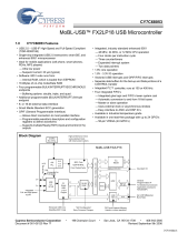
SCHEMATIC DIAGRAM - 1
MAIN C. B
USB CONNECTOR
1
2
3
4
5
ESD PROTECTION
IC202
M24C02WDW1T
NON-VOL
IC301
BA033LBSG
3.3V REG
C102
0.1
CPU
89
56
12
34
14
7
11 10
12 13
9
8
10
13 12
1
34
56
2
14
7
11
APW
A
A
A
A
APW
APW
A
A
APW
APW
APW
APW
APW
(CONNECTOR FOR PCT TERMINAL)

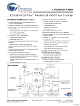
WIRING - 1
-6-
BLK
BLK
WHT
WHT
GRN
RED
BLK
CON101
USB
CONNECTOR
3 14
5 7 8
2325272931
33
11
9
753
1
34
36
38
40
42
22
20
18
16
14
44
1
3 5 7
31 5 7
1214 10 8
1214 10 8
12
1 2 3 5
4
1
134
875
3
4
5
1
3578
3
1
1
3
5
7
14
12
10
8
578
9 11 13 1516
9 11 13 1516
BLU
VLT
RED
YEL
ORG
BLK
GRN
CN104
(CONNECTOR FOR PCT TERMINAL)
D502
USB READY
D502
DATA
2
1
3
5
68
7
10
MAIN C. B
123456789101112131415
A
B
C
D
E
F
G
H
I
J
K
L
M
N
O
P
Q
R
S
T
U

-7-
Pin No. Pin Name I/O Description
IC DESCRIPTION -1/1 (AN2136SC) -1/2
1
2
3 ~ 6
7
8
9
10
11
12
13
14
15
16
17
18
19
20
21
22
23
GND
CLK24
GND
AGND
XIN
XOUT
AVCC
VCC
GND
RESET
PC0/RXD0
PC1/TXD0
____
PC2/INT0
____
PC3/INT1
PC4/T0
PC5/T1
___
PC6/WR
___
PC7/RD
VCC
GND
–
O
–
–
I
O
I
I
–
I
I/O
I/O
I/O
I/O
I/O
I/O
I/O
I/O
I
–
Ground
24 MHz clock, phase locked to the 12 MHz input clock.
Ground
Analog ground. Connect to ground with as short a path as possible.
Connect this signal to a 12 MHz series resonant, fundamental mode crystal and 22-33 pF
capacitor to GND.
Analog VCC. This signal provides power to the analog circuit.
3.3V power source
Ground
Active high reset.
Multiplexed pin whose function is selected by the “RXD0” bit of the PORTCCFG register. If
RXD0=0, the pin is the bi-directional I/O port bit PC0. If RXD0 = 1 the pin is the active-high
RXD0 from 8051 UART0, which provides data to the UART in all modes.
Multiplexed pin whose function is selected by the “TXD0” bit of the PORTCCFG register. If
TXD0=0, the pin is the bi-directional I/O port bit PC1. If TXD0 = 1 the pin is the active-high
TXD0 signal for 8051 UART0, which provides the output clcok in sync mode, and the output
data in async mode.
Multiplexed pin whose function is selected by the “INT0” bit of the PORTCCFG register. If
INT0=0, the pin is the bi-directional I/O port bit PC2. If INT0 = 1 the pin is the active-low 8051
INT0 interrupt input signal, which is either edge triggered (IT0=1) or level triggered (IT0=0).
Multiplexed pin whose function is selected by the “INT1” bit of the PORTCCFG register. If
INT1=0, the pin is the bi-directional I/O port bit PC3. If INT1 = 1 the pin is the active-low 8051
INT1 interrupt input signal, which is either edge triggered (IT1=1) or level triggered (IT1=0).
Multiplexed pin whose function is selected by the “T0” bit of the PORTCCFG register. If T0=0,
the pin is the bi-directional I/O port bit PC4. If T0 = 1 the pin is the active-high T0 signal for
8051 Timer 0, which provides the input to Timer 0 when C/T0 is 1. When C/T0 is 0, Timer0
does not use this bit.
Multiplexed pin whose function is selected by the “T1” bit of the PORTCCFG register. If T1=0,
the pin is the bi-directional I/O port bit PC5. If T1 = 1 the pin is the active-high T1 signal from
8051 Timer 1, which provides the input to Timer 1 when C/T1 is 1. When C/T0 is 0, Timer1
does not use this bit.
Multiplexed pin whose function is selected by the “WR” bit of the PORTCCFG register. If
WR=0, the pin is the bi-directional I/O port bit PC6. If WR = 1 the pin is the active-low write
signal for external memory.
Multiplexed pin whose function is selected by the “RD” bit of the PORTCCFG register. If
RD=0, the pin is the bi-directional I/O port bit PC7. If RD = 1 the pin is the active-low read
signal for external memory.
3.3V power source
Ground

-8-
Pin No. Pin Name I/O Description
24 ~ 31
32
33
34
35
36
37
38
39
40
41
42
43
44
D0 ~ D7
BKPT
VCC
GND
SDA
SCL
_________
WAKEUP
GND
____
PA4/FWR
____
PA5/FRD
USBD-
USBD+
________
DISCON
VCC
8051 data bus. This bi-directiona bus is high-impedance when inactive, input for bus reads, and
output for bus writes. The data bus is also used to transfer data directly to and from internal EZ-
____ ____
USB FIFOS under control of the FRD and FWR strobes. D0-D7 are active only for external bus
accesses, and are driven low in suspend.
Breakpoint. This pin goes active (high) when the 8051 address bus matches the BPADDRH/L
registers and breakpoints are enebled in the USBBAV register (BPEN=1). If the BPPULSE bit in
the USBBAV register is HI, this signal pulses high for eight 24 MHz clocks. If the BPPULSE bit
is LO, the signal remains high until the 8051 clears the BREAK bit (by writing 1 to it) in the
USBBAV register.
3.3V power source
Ground
I
2
C data. Connect to VCC with a 2.2 k resistor.
I
2
C clock. Connect to VCC with a 2.2 k resistor.
USBwakeup. If the 8051is unsuspend, a high to low edge on this pin starts up the oscillator and
interrupts the 8051to allow it to exit the suspend mode.
Ground
Multiplexed pin whose function is selected by the “FWR” (Fast Write) bit of the PORTACFG
register. If FWR=0, the pin is the bi-directional I/O port pin PA4. If FWR = 1 the pin is the write
strobe for an external FIFO.
Multiplexed pin whose function is selected by the “FRD” (Fast Read) bit of the PORTACFG
register. If FRD=0, the pin is the bi-directional I/O port pin PA5. If FRD = 1 the pin is the read
strobe for an external FIFO.
USB D - signal. Connect to the USB D - signal.
USB D+ signal. Connect to the USB D + signal.
Disconnect. This signal drvives low when the 8051 sets the DISCON bit HI (USBCS3). When
________
the DISCON bit is LO, the DISCON pin either drivers high or floats, depending on the state of
the DISCOE bit (USBCS2).
3.3V power source
I/O
O
–
–
O
O
I
–
I/O
I/O
I/O
I/O
O
I
IC DESCRIPTION -1/1 (AN2136SC) -2/2

-9-
MECHANICAL MAIN PARTS LIST 1/1
REF. NO PART NO. KANRI DESCRIPTION
NO.
1 8A-XMB-002-010 CABI,TOP
2 8A-XMB-003-010 WINDOW,LED
3 8A-XMB-001-010 CABI,BOT
4 87-B10-024-310 VT2+1.7-6 W/O

-10-
COLOR NAME TABLE
Basic color symbol Color Basic color symbol Color Basic color symbol Color
B Black C Cream D Orange
G Green H Gray L Blue
LT Transparent Blue N Gold P Pink
R Red S Silver ST Titan Silver
T Brown V Violet W White
WT Transparent White Y Yellow YT Transparent Yellow
LM Metallic Blue LL Light Blue GT Transparent Green
LD Dark Blue DT Transparent Orange GM Metallic Green
YM Metallic Yellow DM Metallic Orange PT Transparent Pink
LA Aqua Blue GL Light Green
COLOR NAME TABLE

2–11, IKENOHATA 1–CHOME, TAITO-KU, TOKYO 110-8710, JAPAN TEL:03 (3827) 3111
920074
Printed in Singapore
/