Page is loading ...

MELSEC iQ-R Laser Displacement Sensor
Control Module User's Manual (Application)
-R60MH112NA


1
SAFETY PRECAUTIONS
(Read these precautions before using this product.)
Before using this product, please read this manual and the relevant manuals carefully and pay full attention to safety to handle
the product correctly.
The precautions given in this manual are concerned with this product only. For the safety precautions of the programmable
controller system, refer to the MELSEC iQ-R Module Configuration Manual.
In this manual, the safety precautions are classified into two levels: " WARNING" and " CAUTION".
Under some circumstances, failure to observe the precautions given under " CAUTION" may lead to serious
consequences.
Observe the precautions of both levels because they are important for personal and system safety.
Make sure that the end users read this manual and then keep the manual in a safe place for future reference.
[Precautions for Using Laser Products]
WARNING
● The laser products use semiconductor laser light sources. When handling laser products, observe the
following because human access to laser radiation may result in injury.
(1) Do not disassemble the laser products. Doing so may result in exposure to laser radiation.
(2) Shut off the external power supply (all phases) to stop laser emission before replacing a failed
laser product or changing the layout.
● Observe the following handling precautions for the laser products in each class.
(1) Class 3R laser products
• Do not aim the laser beam at people.
• Do not directly look at or come in contact with the laser beam and its reflection from a specular
surface (such as a mirror). In addition, never look at the beam and its reflection through optical
instruments (such as a microscope and a telescope).
• Shorten the beam paths as much as possible to prevent diffusion of laser beams. Terminate the
laser beams at the end of their paths by diffusely reflecting materials of appropriate reflectivity
and thermal properties or by absorbers.
• Locate the beam path above or below the eye level. Wearing protective eyewear is
recommended when handling the laser products.
• Install the laser products carefully so that the laser beam is not unintentionally reflected from
specular surfaces.
(2) Class 2 laser products
• Do not aim the laser beam at people.
• Do not stare into the laser beam and its reflection from specular surfaces.
• To prevent exposure to laser radiation (specularly or diffusely reflected laser beams), install a
protective enclosure with an appropriate reflectance.
• Locate the beam path above or below the eye level.
(3) Class 1 laser products
• Do not stare into the laser beam and its reflection from specular surfaces.
WARNING
Indicates that incorrect handling may cause hazardous conditions, resulting in
death or severe injury.
CAUTION
Indicates that incorrect handling may cause hazardous conditions, resulting in
minor or moderate injury or property damage.

2
[Design Precautions]
WARNING
● Configure safety circuits external to the programmable controller to ensure that the entire system
operates safely even when a fault occurs in the external power supply or the programmable controller.
Failure to do so may result in an accident due to an incorrect output or malfunction.
(1) Emergency stop circuits, protection circuits, and protective interlock circuits for conflicting
operations (such as forward/reverse rotations or upper/lower limit positioning) must be configured
external to the programmable controller.
(2) When the programmable controller detects an abnormal condition, it stops the operation and all
outputs are:
• Turned off if the overcurrent or overvoltage protection of the power supply module is activated.
• Held or turned off according to the parameter setting if the self-diagnostic function of the CPU
module detects an error such as a watchdog timer error.
(3) All outputs may be turned on if an error occurs in a part, such as an I/O control part, where the
CPU module cannot detect any error. To ensure safety operation in such a case, provide a safety
mechanism or a fail-safe circuit external to the programmable controller. For a fail-safe circuit
example, refer to "General Safety Requirements" in the MELSEC iQ-R Module Configuration
Manual.
(4) Outputs may remain on or off due to a failure of a component such as a relay and transistor in an
output circuit. Configure an external circuit for monitoring output signals that could cause a
serious accident.
● In an output circuit, when a load current exceeding the rated current or an overcurrent caused by a
load short-circuit flows for a long time, it may cause smoke and fire. To prevent this, configure an
external safety circuit, such as a fuse.
● For the operating status of each station after a communication failure, refer to manuals for the network
used. For the manuals, please consult your local Mitsubishi representative. Incorrect output or
malfunction due to a communication failure may result in an accident.
● When connecting an external device with a CPU module or intelligent function module to modify data
of a running programmable controller, configure an interlock circuit in the program to ensure that the
entire system will always operate safely. For other forms of control (such as program modification,
parameter change, forced output, or operating status change) of a running programmable controller,
read the relevant manuals carefully and ensure that the operation is safe before proceeding. Improper
operation may damage machines or cause accidents.

3
[Design Precautions]
WARNING
● Especially, when a remote programmable controller is controlled by an external device, immediate
action cannot be taken if a problem occurs in the programmable controller due to a communication
failure. To prevent this, configure an interlock circuit in the program, and determine corrective actions
to be taken between the external device and CPU module in case of a communication failure.
● Do not write any data to the "system area" and "write-protect area" of the buffer memory in the
module. Also, do not use any "use prohibited" signals as an output signal from the CPU module to
each module. Doing so may cause malfunction of the programmable controller system. For the
"system area", "write-protect area", and the "use prohibited" signals, refer to the user's manual for the
module used. For areas used for safety communications, they are protected from being written by
users, and thus safety communications failure caused by data writing does not occur.
● If a communication cable is disconnected, the network may be unstable, resulting in a communication
failure of multiple stations. Configure an interlock circuit in the program to ensure that the entire
system will always operate safely even if communications fail. Failure to do so may result in an
accident due to an incorrect output or malfunction. When safety communications are used, an
interlock by the safety station interlock function protects the system from an incorrect output or
malfunction.
● Provide safety measures such as a dual safety mechanism when the module is used for applications
that have the possibility of causing physical injury or serious damage.

4
[Design Precautions]
CAUTION
● Do not install the control lines or communication cables together with the main circuit lines or power
cables. Doing so may result in malfunction due to electromagnetic interference. Keep a distance of
100mm or more between those cables.
● During control of an inductive load such as a lamp, heater, or solenoid valve, a large current
(approximately ten times greater than normal) may flow when the output is turned from off to on.
Therefore, use a module that has a sufficient current rating.
● After the CPU module is powered on or is reset, the time taken to enter the RUN status varies
depending on the system configuration, parameter settings, and/or program size. Design circuits so
that the entire system will always operate safely, regardless of the time.
● Do not power off the programmable controller or reset the CPU module while the settings are being
written. Doing so will make the data in the flash ROM and SD memory card undefined. The values
need to be set in the buffer memory and written to the flash ROM and SD memory card again. Doing
so also may cause malfunction or failure of the module.
● When changing the operating status of the CPU module from external devices (such as the remote
RUN/STOP functions), select "Do Not Open by Program" for "Opening Method" of "Module
Parameter". If "Open by Program" is selected, an execution of the remote STOP function causes the
communication line to close. Consequently, the CPU module cannot reopen the line, and external
devices cannot execute the remote RUN function.
● Do not use the laser displacement sensor outside of its specifications (such as ratings or
environments). Doing so may result in overheating or smoke.

5
[Design Precautions]
[Security Precautions]
[Installation Precautions]
[Installation Precautions]
CAUTION
● Do not disassemble or modify the modules. Doing so may cause failure, malfunction, injury, or a fire.
● Do not touch any terminal while power is on. Doing so will cause electric shock or malfunction.
WARNING
● To maintain the security (confidentiality, integrity, and availability) of the programmable controller and
the system against unauthorized access, denial-of-service (DoS) attacks, computer viruses, and other
cyberattacks from external devices via the network, take appropriate measures such as firewalls,
virtual private networks (VPNs), and antivirus solutions.
WARNING
● Shut off the external power supply (all phases) used in the system before mounting or removing the
module. Failure to do so may result in electric shock or cause the module to fail or malfunction.
CAUTION
● Use the programmable controller in an environment that meets the general specifications in the Safety
Guidelines included with the base unit. Failure to do so may result in electric shock, fire, malfunction,
or damage to or deterioration of the product.
● To mount a module, place the concave part(s) located at the bottom onto the guide(s) of the base unit,
and push in the module until the hook(s) located at the top snaps into place. Incorrect interconnection
may cause malfunction, failure, or drop of the module.
● To mount a module with no module fixing hook, place the concave part(s) located at the bottom onto
the guide(s) of the base unit, push in the module, and fix it with screw(s). Incorrect interconnection
may cause malfunction, failure, or drop of the module.
● When using an extension cable, connect it to the extension cable connector of the base unit securely.
Check the connection for looseness. Poor contact may cause malfunction.
● When using an SD memory card, fully insert it into the SD memory card slot. Check that it is inserted
completely. Poor contact may cause malfunction.
● Securely insert an extended SRAM cassette or a battery-less option cassette into the cassette
connector of the CPU module. After insertion, close the cassette cover and check that the cassette is
inserted completely. Poor contact may cause malfunction.
● Do not directly touch any conductive parts and electronic components of the module, SD memory
card, extended SRAM cassette, battery-less option cassette, or connector. Doing so can cause
malfunction or failure of the module.

6
[Wiring Precautions]
[Wiring Precautions]
WARNING
● Shut off the external power supply (all phases) used in the system before installation and wiring.
Failure to do so may result in electric shock or cause the module to fail or malfunction.
● After installation and wiring, attach a blank cover module (RG60) to each empty slot and an included
extension connector protective cover to the unused extension cable connector before powering on the
system for operation. Failure to do so may result in electric shock.
CAUTION
● Individually ground the FG and LG terminals of the programmable controller with a ground resistance
of 100 ohms or less. Failure to do so may result in electric shock or malfunction.
● Check the rated voltage and signal layout before wiring to the module, and connect the cables
correctly. Connecting a power supply with a different voltage rating or incorrect wiring may cause fire
or failure.
● Connectors for external devices must be crimped or pressed with the tool specified by the
manufacturer, or must be correctly soldered. Incomplete connections may cause short circuit, fire, or
malfunction.
● Securely connect the connector to the module. Poor contact may cause malfunction.
● Do not install the control lines or communication cables together with the main circuit lines or power
cables. Doing so may result in malfunction due to noise. Keep a distance of 100mm or more between
those cables. Keep a distance of 100mm or more between those cables.
● Place the cables in a duct or clamp them. If not, dangling cables may swing or inadvertently be pulled,
resulting in malfunction or damage to modules or cables.
In addition, the weight of the cables may put stress on modules in an environment of strong vibrations
and shocks.
Do not clamp the extension cables with the jacket stripped. Doing so may change the characteristics
of the cables, resulting in malfunction.
● Check the interface type and correctly connect the cable. Incorrect wiring (connecting the cable to an
incorrect interface) may cause failure of the module and external device.
● Tighten the connector screws within the specified torque range. Undertightening can cause drop of
the screw, short circuit, fire, or malfunction. Overtightening can damage the screw and/or module,
resulting in drop, short circuit, fire, or malfunction.
● When disconnecting the cable from the module, do not pull the cable by the cable part. For the cable
with connector, hold the connector part of the cable. Pulling the cable connected to the module may
result in malfunction or damage to the module or cable.
● Prevent foreign matter such as dust or wire chips from entering the module. Such foreign matter can
cause a fire, failure, or malfunction.
● A protective film is attached to the top of the module to prevent foreign matter, such as wire chips,
from entering the module during wiring. Do not remove the film during wiring. Remove it for heat
dissipation before system operation.

7
[Wiring Precautions]
[Startup and Maintenance Precautions]
CAUTION
● Programmable controllers must be installed in control panels. Connect the main power supply to the
power supply module in the control panel through a relay terminal block. Wiring and replacement of a
power supply module must be performed by qualified maintenance personnel with knowledge of
protection against electric shock. For wiring, refer to the MELSEC iQ-R Module Configuration Manual.
● For Ethernet cables to be used in the system, select the ones that meet the specifications in the user's
manual for the module used. If not, normal data transmission is not guaranteed.
● Do not apply the 24VDC power before connecting a sensor head. If the power is applied before wiring,
normal data transmission is not guaranteed.
WARNING
● Do not touch any terminal while power is on. Doing so will cause electric shock or malfunction.
● Correctly connect the battery connector. Do not charge, disassemble, heat, short-circuit, solder, or
throw the battery into the fire. Also, do not expose it to liquid or strong shock. Doing so will cause the
battery to produce heat, explode, ignite, or leak, resulting in injury and fire.
● Shut off the external power supply (all phases) used in the system before cleaning the module or
retightening the connector screws or module fixing screws. Failure to do so may result in electric
shock.

8
[Startup and Maintenance Precautions]
CAUTION
● When connecting an external device with a CPU module or intelligent function module to modify data
of a running programmable controller, configure an interlock circuit in the program to ensure that the
entire system will always operate safely. For other forms of control (such as program modification,
parameter change, forced output, or operating status change) of a running programmable controller,
read the relevant manuals carefully and ensure that the operation is safe before proceeding. Improper
operation may damage machines or cause accidents.
● Especially, when a remote programmable controller is controlled by an external device, immediate
action cannot be taken if a problem occurs in the programmable controller due to a communication
failure. To prevent this, configure an interlock circuit in the program, and determine corrective actions
to be taken between the external device and CPU module in case of a communication failure.
● Do not disassemble or modify the modules. Doing so may cause failure, malfunction, injury, or a fire.
● Use any radio communication device such as a cellular phone or PHS (Personal Handy-phone
System) more than 25cm away in all directions from the programmable controller. Failure to do so
may cause malfunction.
● Shut off the external power supply (all phases) used in the system before mounting or removing the
module. Failure to do so may cause the module to fail or malfunction.
● Tighten the screws within the specified torque range. Undertightening can cause drop of the
component or wire, short circuit, or malfunction. Overtightening can damage the screw and/or module,
resulting in drop, short circuit, or malfunction.
● After the first use of the product, do not perform each of the following operations more than 50 times
(IEC 61131-2/JIS B 3502 compliant).
Exceeding the limit may cause malfunction.
• Mounting/removing the module to/from the base unit
• Inserting/removing the extended SRAM cassette or battery-less option cassette to/from the
CPU module
• Mounting/removing the terminal block to/from the module
● After the first use of the product, do not insert/remove the SD memory card to/from the CPU module
more than 500 times. Exceeding the limit may cause malfunction.
● Do not touch the metal terminals on the back side of the SD memory card. Doing so may cause
malfunction or failure of the module.
● Do not touch the integrated circuits on the circuit board of an extended SRAM cassette or a battery-
less option cassette. Doing so may cause malfunction or failure of the module.
● Do not drop or apply shock to the battery to be installed in the module. Doing so may damage the
battery, causing the battery fluid to leak inside the battery. If the battery is dropped or any shock is
applied to it, dispose of it without using.
● Startup and maintenance of a control panel must be performed by qualified maintenance personnel
with knowledge of protection against electric shock. Lock the control panel so that only qualified
maintenance personnel can operate it.
● Before handling the module, touch a conducting object such as a grounded metal to discharge the
static electricity from the human body. Failure to do so may cause the module to fail or malfunction.

9
[Operating Precautions]
[Disposal Precautions]
[Transportation Precautions]
CAUTION
● When changing data and operating status, and modifying program of the running programmable
controller from an external device such as a personal computer connected to an intelligent function
module, read relevant manuals carefully and ensure the safety before operation. Incorrect change or
modification may cause system malfunction, damage to the machines, or accidents.
● Do not power off the programmable controller or reset the CPU module while the setting values in the
buffer memory are being written to the flash ROM in the module. Doing so will make the data in the
flash ROM and SD memory card undefined. The values need to be set in the buffer memory and
written to the flash ROM and SD memory card again. Doing so can cause malfunction or failure of the
module.
CAUTION
● When disposing of this product, treat it as industrial waste.
● When disposing of batteries, separate them from other wastes according to the local regulations. For
details on battery regulations in EU member states, refer to the MELSEC iQ-R Module Configuration
Manual.
CAUTION
● When transporting lithium batteries, follow the transportation regulations. For details on the regulated
models, refer to the MELSEC iQ-R Module Configuration Manual.
● The halogens (such as fluorine, chlorine, bromine, and iodine), which are contained in a fumigant
used for disinfection and pest control of wood packaging materials, may cause failure of the product.
Prevent the entry of fumigant residues into the product or consider other methods (such as heat
treatment) instead of fumigation. The disinfection and pest control measures must be applied to
unprocessed raw wood.

10
CONDITIONS OF USE FOR THE PRODUCT
INTRODUCTION
Thank you for purchasing the Mitsubishi Electric MELSEC iQ-R series programmable controllers.
This manual describes the functions, parameter settings, and troubleshooting of the relevant products listed below.
Before using this product, please read this manual and the relevant manuals carefully and develop familiarity with the
functions and performance of the MELSEC iQ-R series programmable controller to handle the product correctly.
When applying the program examples provided in this manual to an actual system, ensure the applicability and confirm that it
will not cause system control problems.
Please make sure that the end users read this manual.
Relevant product
R60MH112NA
(1) MELSEC programmable controller ("the PRODUCT") shall be used in conditions;
i) where any problem, fault or failure occurring in the PRODUCT, if any, shall not lead to any major or serious accident;
and
ii) where the backup and fail-safe function are systematically or automatically provided outside of the PRODUCT for the
case of any problem, fault or failure occurring in the PRODUCT.
(2) The PRODUCT has been designed and manufactured for the purpose of being used in general industries.
MITSUBISHI ELECTRIC SHALL HAVE NO RESPONSIBILITY OR LIABILITY (INCLUDING, BUT NOT LIMITED TO
ANY AND ALL RESPONSIBILITY OR LIABILITY BASED ON CONTRACT, WARRANTY, TORT, PRODUCT
LIABILITY) FOR ANY INJURY OR DEATH TO PERSONS OR LOSS OR DAMAGE TO PROPERTY CAUSED BY the
PRODUCT THAT ARE OPERATED OR USED IN APPLICATION NOT INTENDED OR EXCLUDED BY
INSTRUCTIONS, PRECAUTIONS, OR WARNING CONTAINED IN MITSUBISHI ELECTRIC USER'S, INSTRUCTION
AND/OR SAFETY MANUALS, TECHNICAL BULLETINS AND GUIDELINES FOR the PRODUCT.
("Prohibited Application")
Prohibited Applications include, but not limited to, the use of the PRODUCT in;
• Nuclear Power Plants and any other power plants operated by Power companies, and/or any other cases in which the
public could be affected if any problem or fault occurs in the PRODUCT.
• Railway companies or Public service purposes, and/or any other cases in which establishment of a special quality
assurance system is required by the Purchaser or End User.
• Aircraft or Aerospace, Medical applications, Train equipment, transport equipment such as Elevator and Escalator,
Incineration and Fuel devices, Vehicles, Manned transportation, Equipment for Recreation and Amusement, and
Safety devices, handling of Nuclear or Hazardous Materials or Chemicals, Mining and Drilling, and/or other
applications where there is a significant risk of injury to the public or property.
Notwithstanding the above restrictions, Mitsubishi Electric may in its sole discretion, authorize use of the PRODUCT in
one or more of the Prohibited Applications, provided that the usage of the PRODUCT is limited only for the specific
applications agreed to by Mitsubishi Electric and provided further that no special quality assurance or fail-safe,
redundant or other safety features which exceed the general specifications of the PRODUCTs are required. For details,
please contact the Mitsubishi Electric representative in your region.
(3) Mitsubishi Electric shall have no responsibility or liability for any problems involving programmable controller trouble and
system trouble caused by DoS attacks, unauthorized access, computer viruses, and other cyberattacks.

11
CONTENTS
CONTENTS
SAFETY PRECAUTIONS . . . . . . . . . . . . . . . . . . . . . . . . . . . . . . . . . . . . . . . . . . . . . . . . . . . . . . . . . . . . . . . . . . . .1
CONDITIONS OF USE FOR THE PRODUCT . . . . . . . . . . . . . . . . . . . . . . . . . . . . . . . . . . . . . . . . . . . . . . . . . . .10
INTRODUCTION. . . . . . . . . . . . . . . . . . . . . . . . . . . . . . . . . . . . . . . . . . . . . . . . . . . . . . . . . . . . . . . . . . . . . . . . . .10
RELEVANT MANUALS . . . . . . . . . . . . . . . . . . . . . . . . . . . . . . . . . . . . . . . . . . . . . . . . . . . . . . . . . . . . . . . . . . . . .13
TERMS . . . . . . . . . . . . . . . . . . . . . . . . . . . . . . . . . . . . . . . . . . . . . . . . . . . . . . . . . . . . . . . . . . . . . . . . . . . . . . . . .13
GENERIC TERMS AND ABBREVIATIONS. . . . . . . . . . . . . . . . . . . . . . . . . . . . . . . . . . . . . . . . . . . . . . . . . . . . . .14
CHAPTER 1 FUNCTIONS 15
1.1 Sensing Function . . . . . . . . . . . . . . . . . . . . . . . . . . . . . . . . . . . . . . . . . . . . . . . . . . . . . . . . . . . . . . . . . . . . . . . 15
1.2 Memory Operation Function. . . . . . . . . . . . . . . . . . . . . . . . . . . . . . . . . . . . . . . . . . . . . . . . . . . . . . . . . . . . . . . 24
1.3 Buffering Function . . . . . . . . . . . . . . . . . . . . . . . . . . . . . . . . . . . . . . . . . . . . . . . . . . . . . . . . . . . . . . . . . . . . . . 27
1.4 Intelligent Function . . . . . . . . . . . . . . . . . . . . . . . . . . . . . . . . . . . . . . . . . . . . . . . . . . . . . . . . . . . . . . . . . . . . . .41
External power supply interruption detection function. . . . . . . . . . . . . . . . . . . . . . . . . . . . . . . . . . . . . . . . . . . . . 41
Received light intensity waveform acquisition function . . . . . . . . . . . . . . . . . . . . . . . . . . . . . . . . . . . . . . . . . . . . 42
Logging function . . . . . . . . . . . . . . . . . . . . . . . . . . . . . . . . . . . . . . . . . . . . . . . . . . . . . . . . . . . . . . . . . . . . . . . . . 43
1.5 Recipe Selection Function . . . . . . . . . . . . . . . . . . . . . . . . . . . . . . . . . . . . . . . . . . . . . . . . . . . . . . . . . . . . . . . . 46
CHAPTER 2 PARAMETER SETTINGS 47
2.1 Parameter Setting Procedure. . . . . . . . . . . . . . . . . . . . . . . . . . . . . . . . . . . . . . . . . . . . . . . . . . . . . . . . . . . . . .47
2.2 Parameter Settings in the Engineering Tool . . . . . . . . . . . . . . . . . . . . . . . . . . . . . . . . . . . . . . . . . . . . . . . . . . 48
Refresh settings. . . . . . . . . . . . . . . . . . . . . . . . . . . . . . . . . . . . . . . . . . . . . . . . . . . . . . . . . . . . . . . . . . . . . . . . . . 48
Refresh processing time . . . . . . . . . . . . . . . . . . . . . . . . . . . . . . . . . . . . . . . . . . . . . . . . . . . . . . . . . . . . . . . . . . . 49
2.3 Parameter Settings in the Setting Tool . . . . . . . . . . . . . . . . . . . . . . . . . . . . . . . . . . . . . . . . . . . . . . . . . . . . . . 50
CHAPTER 3 PROGRAMMING 51
3.1 Control Module Program Example. . . . . . . . . . . . . . . . . . . . . . . . . . . . . . . . . . . . . . . . . . . . . . . . . . . . . . . . . . 51
System configuration example . . . . . . . . . . . . . . . . . . . . . . . . . . . . . . . . . . . . . . . . . . . . . . . . . . . . . . . . . . . . . . 51
Parameter settings . . . . . . . . . . . . . . . . . . . . . . . . . . . . . . . . . . . . . . . . . . . . . . . . . . . . . . . . . . . . . . . . . . . . . . . 51
Program example . . . . . . . . . . . . . . . . . . . . . . . . . . . . . . . . . . . . . . . . . . . . . . . . . . . . . . . . . . . . . . . . . . . . . . . . 53
3.2 Program Example of Collecting the Measurement Values Using the Logging Function . . . . . . . . . . . . . . 57
System configuration example . . . . . . . . . . . . . . . . . . . . . . . . . . . . . . . . . . . . . . . . . . . . . . . . . . . . . . . . . . . . . . 57
Parameter settings . . . . . . . . . . . . . . . . . . . . . . . . . . . . . . . . . . . . . . . . . . . . . . . . . . . . . . . . . . . . . . . . . . . . . . . 57
Program example . . . . . . . . . . . . . . . . . . . . . . . . . . . . . . . . . . . . . . . . . . . . . . . . . . . . . . . . . . . . . . . . . . . . . . . . 60
CHAPTER 4 TIMING CHARTS 71
4.1 Normal Measurement . . . . . . . . . . . . . . . . . . . . . . . . . . . . . . . . . . . . . . . . . . . . . . . . . . . . . . . . . . . . . . . . . . . . 71
4.2 Peak Measurement/Bottom Measurement . . . . . . . . . . . . . . . . . . . . . . . . . . . . . . . . . . . . . . . . . . . . . . . . . . . 72
4.3 Peak to Peak Measurement . . . . . . . . . . . . . . . . . . . . . . . . . . . . . . . . . . . . . . . . . . . . . . . . . . . . . . . . . . . . . . . 74
4.4 Laser Control . . . . . . . . . . . . . . . . . . . . . . . . . . . . . . . . . . . . . . . . . . . . . . . . . . . . . . . . . . . . . . . . . . . . . . . . . . . 75
CHAPTER 5 TROUBLESHOOTING 76
5.1 Checking with LEDs . . . . . . . . . . . . . . . . . . . . . . . . . . . . . . . . . . . . . . . . . . . . . . . . . . . . . . . . . . . . . . . . . . . . . 76
Control module . . . . . . . . . . . . . . . . . . . . . . . . . . . . . . . . . . . . . . . . . . . . . . . . . . . . . . . . . . . . . . . . . . . . . . . . . . 76
Sensor head . . . . . . . . . . . . . . . . . . . . . . . . . . . . . . . . . . . . . . . . . . . . . . . . . . . . . . . . . . . . . . . . . . . . . . . . . . . . 77
5.2 Checking the Module Status . . . . . . . . . . . . . . . . . . . . . . . . . . . . . . . . . . . . . . . . . . . . . . . . . . . . . . . . . . . . . . 78
5.3 Troubleshooting by Symptom . . . . . . . . . . . . . . . . . . . . . . . . . . . . . . . . . . . . . . . . . . . . . . . . . . . . . . . . . . . . . 80
5.4 Error Code List . . . . . . . . . . . . . . . . . . . . . . . . . . . . . . . . . . . . . . . . . . . . . . . . . . . . . . . . . . . . . . . . . . . . . . . . . 84

12
5.5 Alarm Code List. . . . . . . . . . . . . . . . . . . . . . . . . . . . . . . . . . . . . . . . . . . . . . . . . . . . . . . . . . . . . . . . . . . . . . . . . 86
5.6 Event List . . . . . . . . . . . . . . . . . . . . . . . . . . . . . . . . . . . . . . . . . . . . . . . . . . . . . . . . . . . . . . . . . . . . . . . . . . . . . . 87
APPENDICES 88
Appendix 1 Module Label . . . . . . . . . . . . . . . . . . . . . . . . . . . . . . . . . . . . . . . . . . . . . . . . . . . . . . . . . . . . . . . . . . . . . . 88
Appendix 2 I/O Signals . . . . . . . . . . . . . . . . . . . . . . . . . . . . . . . . . . . . . . . . . . . . . . . . . . . . . . . . . . . . . . . . . . . . . . . . 89
List of I/O signals. . . . . . . . . . . . . . . . . . . . . . . . . . . . . . . . . . . . . . . . . . . . . . . . . . . . . . . . . . . . . . . . . . . . . . . . . 89
Details of I/O signals . . . . . . . . . . . . . . . . . . . . . . . . . . . . . . . . . . . . . . . . . . . . . . . . . . . . . . . . . . . . . . . . . . . . . .90
Appendix 3 Buffer Memory . . . . . . . . . . . . . . . . . . . . . . . . . . . . . . . . . . . . . . . . . . . . . . . . . . . . . . . . . . . . . . . . . . . . 100
List of buffer memory addresses . . . . . . . . . . . . . . . . . . . . . . . . . . . . . . . . . . . . . . . . . . . . . . . . . . . . . . . . . . . . 100
Details of buffer memory addresses . . . . . . . . . . . . . . . . . . . . . . . . . . . . . . . . . . . . . . . . . . . . . . . . . . . . . . . . . 105
Appendix 4 Measurement Method by Measurement Object . . . . . . . . . . . . . . . . . . . . . . . . . . . . . . . . . . . . . . . . . 126
Appendix 5 Supplemental Remarks for Functions . . . . . . . . . . . . . . . . . . . . . . . . . . . . . . . . . . . . . . . . . . . . . . . . . 127
Alarm setting and outputs . . . . . . . . . . . . . . . . . . . . . . . . . . . . . . . . . . . . . . . . . . . . . . . . . . . . . . . . . . . . . . . . . 127
Conditions for unfixed output data. . . . . . . . . . . . . . . . . . . . . . . . . . . . . . . . . . . . . . . . . . . . . . . . . . . . . . . . . . . 128
Appendix 6 CSV File Format of the Continuous Logging Data . . . . . . . . . . . . . . . . . . . . . . . . . . . . . . . . . . . . . . . 130
Appendix 7 Using the Module in the Redundant System with Redundant Extension Base Unit . . . . . . . . . . . . 133
Restrictions on functions and specifications . . . . . . . . . . . . . . . . . . . . . . . . . . . . . . . . . . . . . . . . . . . . . . . . . . . 133
Appendix 8 Addition and Change of Functions . . . . . . . . . . . . . . . . . . . . . . . . . . . . . . . . . . . . . . . . . . . . . . . . . . . 134
INDEX 136
REVISIONS. . . . . . . . . . . . . . . . . . . . . . . . . . . . . . . . . . . . . . . . . . . . . . . . . . . . . . . . . . . . . . . . . . . . . . . . . . . . .138
WARRANTY . . . . . . . . . . . . . . . . . . . . . . . . . . . . . . . . . . . . . . . . . . . . . . . . . . . . . . . . . . . . . . . . . . . . . . . . . . . .139
TRADEMARKS . . . . . . . . . . . . . . . . . . . . . . . . . . . . . . . . . . . . . . . . . . . . . . . . . . . . . . . . . . . . . . . . . . . . . . . . . .140

13
RELEVANT MANUALS
e-Manual refers to the Mitsubishi Electric FA electronic book manuals that can be browsed using a dedicated
tool.
e-Manual has the following features:
• Required information can be cross-searched in multiple manuals.
• Other manuals can be accessed from the links in the manual.
• The hardware specifications of each part can be found from the product figures.
• Pages that users often browse can be bookmarked.
• Sample programs can be copied to an engineering tool.
TERMS
Unless otherwise specified, this manual uses the following terms.
Manual name [manual number] Description Available form
MELSEC iQ-R Laser Displacement Sensor Control
Module User's Manual (Application)
[SH-082019ENG] (this manual)
Functions, parameter settings, troubleshooting, I/O signals, and buffer
memory of the control module
Print book
e-Manual
PDF
MELSEC iQ-R Module Configuration Manual
[SH-081262ENG]
The combination of the MELSEC iQ-R series modules, common information
on the installation/wiring in the system, and specifications of the power supply
module, base unit, SD memory card, and battery
Print book
e-Manual
PDF
MELSEC iQ-R Laser Displacement Sensor Control
Module User's Manual (Startup)
[SH-082017ENG]
Specifications, procedures before operation, system configuration, wiring,
and communication examples of the control module
Print book
e-Manual
PDF
MELSEC iQ-R Laser Displacement Sensor Control
Module User's Manual (Sensor Head)
[SH-082023ENG]
Precautions for using the sensor head, installation methods, specifications,
and maintenance and inspection
Print book
e-Manual
PDF
MELSEC iQ-R Laser Displacement Sensor Control
Module Function Block Reference
[BCN-P5999-1039]
Specifications of the MELSEC iQ-R series laser displacement sensor control
module FBs
e-Manual
PDF
GX Works3 Operating Manual
[SH-081215ENG]
System configuration, parameter settings, and online operations of GX
Works3
e-Manual
PDF
Laser Displacement Sensor MH11 SettingTool
Version 2 Operating Manual
[SH-082021ENG]
Operation methods, functions, and error messages of the setting tool.
It also describes the use of the buffering function and the received light
intensity waveform display function, which are useful for an evaluation
analysis of the laser displacement sensor MH11 or for optimum settings.
e-Manual
PDF
Term Description
Buffer memory Memory in an intelligent function module to store data such as setting values and monitor values.
For CPU modules, it refers to memory to store data such as setting values and monitor values of the Ethernet function,
or data used for data communication of the multiple CPU system function.
Device A memory of a CPU module to store data.
Devices such as X, Y, M, D, and others are provided depending on the intended use.
Engineering tool A tool used for setting up programmable controllers, programming, debugging, and maintenance
Intelligent function module A module that has functions other than an input or output, such as an A/D converter module and D/A converter module
Module label A label that represents a memory area (I/O signal or buffer memory area) specific to each module with a given character
string.
For the module used, GX Works3 automatically generates this label, which can be used as a global label.
Redundant system with redundant
extension base unit
A redundant system that is configured using extension base unit(s)

14
GENERIC TERMS AND ABBREVIATIONS
Unless otherwise specified, this manual uses the following generic terms and abbreviations.
Generic term/abbreviation Description
Control module An abbreviation for the MELSEC iQ-R laser displacement sensor control module.
CPU module A generic term for the MELSEC iQ-R series CPU module.
I/O module A generic term for input module, output module, I/O combined module, and interrupt module.
Power supply module An abbreviation for the MELSEC iQ-R series power supply module.
Sensor head An abbreviation for the laser displacement sensor MH11 sensor head.
Setting tool An abbreviation for the laser displacement sensor MH11 SettingTool Version 2.

1 FUNCTIONS
1.1 Sensing Function
15
1
1 FUNCTIONS
1.1 Sensing Function
This function outputs the displacement amount as a measurement result using a laser beam.
This allows for change of the measurement conditions and adjustment and judgment of the measurement result.
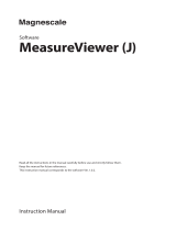
Measurement function
Up to two sensor heads can be connected to the control module. Individual measurement by each sensor head and
calculation of measurement values for two sensor heads can be performed. The following figure shows the operation flow of
each function.
Sampling
Filter
Offset
Filter
Offset
Calibration
Sampling
Calibration
OUT1 data OUT2 data
Output selection (calculation between two sensor heads)
Sensor head A data Sensor head B data
Alarm operation Alarm operation
Zero set Zero set
Analysis mode Analysis mode
Operation coefficient Operation coefficient
Judgment output Judgment output
OUT1 output
OUT2 output
Measurement value of sensor head A Measurement value of sensor head B

16
1 FUNCTIONS
1.1 Sensing Function
Item Description Reference
Sampling The sampling cycle of 10s to 2ms can be selected in eight levels. For details, refer to the sampling cycle in the
following manual.
Laser Displacement Sensor MH11
SettingTool Version 2 Operating Manual
Alarm operation An alarm occurs when the light intensity is saturated, insufficient light
intensity is detected, or a measurement object is not in the
measurement range.
For details, refer to the alarm delay times in
the following manual.
Laser Displacement Sensor MH11
SettingTool Version 2 Operating Manual
Calibration The gap between the actual distance and the measurement value
can be corrected.
Laser Displacement Sensor MH11
SettingTool Version 2 Operating Manual
Measurement value of sensor head A/
sensor head B
The measurement value per sensor head is fixed.
Output selection (calculation between
two sensor heads)
The measurement value of a given sensor head can be output to
OUT1 and OUT2.
Calculation between two sensor heads can be performed.
For details, refer to the output selection in
the following manual.
Laser Displacement Sensor MH11
SettingTool Version 2 Operating Manual
Filter The moving average, low pass filter, and high pass filter can be set for
the measurement value and calculation value.
For details, refer to the filter processing in
the following manual.
Laser Displacement Sensor MH11
SettingTool Version 2 Operating Manual
Zero set The measurement value when the zero set is turned on can be set to
the reference value of measurement (zero). The measurement value
set to the reference value of measurement is cleared when the zero
set is turned off.
Page 20 Zero set
Analysis mode The mode can be selected from four types including peak to peak
measurement.
Laser Displacement Sensor MH11
SettingTool Version 2 Operating Manual
Operation coefficient The operation coefficient can be set for the measurement value.
Offset A set value can be subtracted or added from/to the measurement
value.
Judgment output The output type is determined from HI, GO, or LO output according to
the last result of data processing.
Page 17 Upper/lower limit value of
judgment output

1 FUNCTIONS
1.1 Sensing Function
17
1
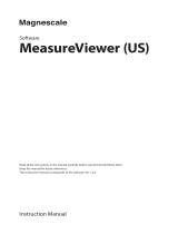
Upper/lower limit value of judgment output
The measurement value can be judged by setting the upper and lower limit values.
The output status changes in three types as follows: Measurement value > Upper limit value: HI output, Lower limit value
Measurement value Upper limit value: GO output, Measurement value < Lower limit value: LO output.
■Supplemental remarks
• The input range of both upper/lower limit values is -950.000000 to 950.000000mm.
• The initial upper limit value is the upper measurement limit (positive number). The initial lower limit value is the lower
measurement limit (negative number).
■Setting method
Use the setting tool.
1. Select the "OUT1" or "OUT2" tab in the main window.
2. Set "Up Lmt Val" and "Lo Lmt Val" under "Judgment Output" in the main window.
Precautions
• Set the upper limit value higher than the lower limit value. When the upper limit value is set to be equal to or lower than the
lower limit value, a setting error occurs and the parameter setting cannot be performed.
• The output type is determined based on the fixed value when an alarm occurs and the measurement value output at alarm
is set to "Fixed Value".
ON
OFF
ON
OFF
ON
OFF
HI output
GO output
LO output
Displacement
amount (+)
Display
Upper limit
value
Lower limit
value
Output status
Output status
Output status
Measurement
value
Measurement
value
<
Lower
limit value
Lower
limit value
Upper
limit value
≤≤
Measurement
value
Upper
limit value
>

18
1 FUNCTIONS
1.1 Sensing Function
Upper/lower limit hysteresis of judgment output
This function stabilizes the judgment output for chattering of the measurement value.
The relationship between the hysteresis value to set and the output turning on/off is shown below. The function acts on the
upper/lower limit values when output is in the ON state.
Ex.
For GO output
If the measurement value fluctuates around the upper/lower limit value of judgment output, output repeats the
on or off state. This may cause unstable judgment output. In this case, set the upper/lower limit hysteresis of
judgment output to prevent such chattering.
■Supplemental remarks
The input range of both upper/lower limit hysteresis values is 0.000000 to 950.000000mm.
The initial values of both upper/lower limit hysteresis are 0.1% of the measurement range.
■Setting method
Use the setting tool.
1. Select the "OUT1" or "OUT2" tab in the main window.
2. Set "Up Lmt Val" and "Lo Lmt Val" under "Judgment Output" in the main window.
Measurement value transition Description Judgment output
(1) Transitions within the range of the upper/lower limit value of judgment output. GO
(2) Transitions from within the range of the upper/lower limit value of judgment
output to outside the lower limit value of judgment output.
GOLO
(3) Transitions from outside the lower limit value of judgment output to within the
lower threshold value.
LOGO
(4) Transitions within the range of the upper/lower limit value of judgment output to
outside the upper limit value of judgment output.
GOHI
(5) Transitions from outside the upper limit value of judgment output to within the
upper limit threshold value.
HIGO
(5)(3)
(4)(2)
(1)
Judgment output
lower limit value
Judgment output
upper limit value
Lower limit
hysteresis of
judgment
output
Upper limit
hysteresis of
judgment
output
Displacement
amount (-)
Displacement
amount (+)
Measurement
center
Measurement value transition
: Judgment output GO
: Judgment output LO or HI
/