Page is loading ...

1
This universal microphone amplifier can work
directly with popular two- and three-pin electret
microphones.
Very good sound quality has been also achieved
due to the use of high performance components:
Elite series capacitors and low-noise operational
amplifier
NE5532. This gives the module good enough
parameters to make it ideal for use with good
quality dynamic microphones.
Characteristics
• non-linear distortion < 0.09% (at maximum gain)
• frequency response > 25 kHz
• adjustable gain from 0.9 to 100×
• stepped and smooth gain adjustment
• power supply circuit for electret microphone
• power supply: 7-24 VDC (non- or rechargeable
batteries)
• board size 30×45 mm
A schematic of the amplifier is shown in Figure 1. As
you can see, the circuit is powered by a single voltage.
An additional circuit R1, C2, R2 is provided to supply
electret microphones. The module includes two stages
with adjustable gain. The first stage gain (U1A) is
stepless adjustable with POT1 potentiometer in the
range 1...10x. The gain of the second stage can be
varied step by step via jumper JP2. If JP2 pins are not
shorted, the gain is greatest, determined by the ratio
R8/R5. When the jumper JP2 in parallel to R8 will
connect resistor R6 or R7, the gain will be smaller.
Parallel connection of R7 (9.1 kΩ) with resistor R8
(22 kΩ) gives a resistance of 6.4 kΩ, which is 3.2x
higher than the resistance of the resultant
combination of R6, R8 and 3.4x lower than the
resistance of R8. With the given component values, the
second stage gain will be: 10x (without jumper), 2.9x
(R7 connected), 0.91x (R6 connected).
In this way, total gain can be precisely adjusted in the
range 0.9...100x. Such a range is completely sufficient
for use with typical microphones, including dynamic
ones, but if you want to
increase maximum gain to 600x (55 dB), you can
reduce the value of R11, even to 360 Ω (which will
increase the first-stage gain even up to 28x) and also
reduce the value of R5, even down to 1 kΩ (by which
the gain of the second stage will increase up to 22x).
In the basic version (also included) you will get
the NE5532 operational amplifier - a circuit developed
specifically for use in audio equipment and frequently
used even today also in professional equipment. The
module deliberately used two active stages - each
Circuit description
Microphone Amplifier
AVT 2728
kits
ASSEMBLY DIFFICULTY
PDF
DOWNLOAD
ZOOM

Fig. 1. Schematic diagram
2
stage provides a large reserve of the gain and
guarantees wide bandwidth and excellent dynamic
parameters. Measurements have shown that even at
maximum gain (100x, i.e. 40 dB) the bandwidth
reaches above 25 kHz. Non-linear distortions are
negligible. At maximum gain in the output signal with
peak-to-peak value of 5V (resulting in 1.8 Vsk), non-
linear distortions were less than 0.09%. At maximum
gain in the output signal with peak-to-peak value of
5 V (resulting in 1.8 Vsk), non-linear distortions were
less than 0.09%. At maximum gain 20x (26 dB), the
distortion and noise (THD+N) of this simple circuit was
less than 0.03%. The module will also work very well
with popular operational amplifier TL072 and TL082.
Although these amplifiers have larger noise, but with
an electret microphone it is not relevant due to the
large signal obtained from such microphones. Current
consumption will then drop to about 3 mA (compared
to about 10 mA with NE5532), which is important for
battery power. Further reduction in current
consumption is possible with the TL062 circuit. Current
consumption will be reduced to around 0.5 mA and,
due to two stages of amplification, even at maximum
gain, the bandwidth will still be wider than 20 kHz.
Alkaline 9 V battery with capacity of 400...500 mAh will
last for many hours supply of such a very economical
amplifier. In light-duty applications where an electret
microphone is used, you can reliably use TL072, TL082
and TL062. Only for operation with a good quality
dynamic microphone, it is advisable to use the NE5532
chip, which will then ensure excellent performance and
will enable full use of advantages of this microphone.
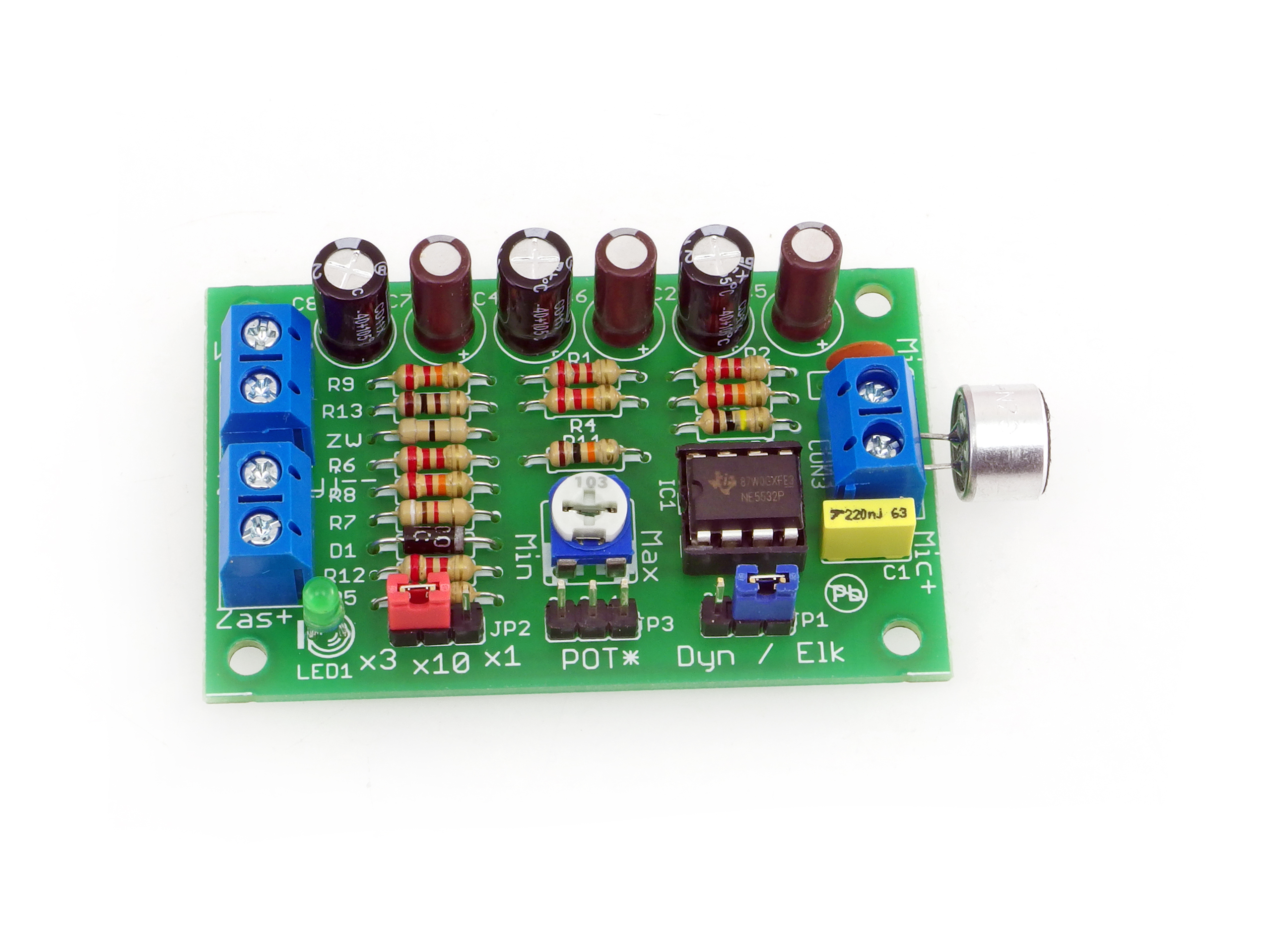
The amplifier is mounted on a printed circuit board,
shown in Figure 2. Its mounting is typical and should
not cause any problems. A socket under the IC will
make it perfectly easy to experiment and compare the
circuit parameters with different operational amplifiers.
In standard, a miniature mounting potentiometer will
be used as POT1 . Optional external potentiometer can
be connected to the JP3 connector marked POT*, then
you do not solder the miniature potentiometer. Due to
possible external interference, such leads should be as
short as possible. Such the potentiometer will be used
to smooth gain control and not as a typical volume
regulator (because you cannot reduce the gain in it to
zero).
The presented module has a high gain, so can easily
"pick up" a variety of interference, including through
the input circuitry, so it is recommended to connect
the microphone using a shielded cable. Figure 3 shows
examples of how to connect electret microphones.
Ensure power supply for the three-pin microphone
directly from the capacitor C2, leaving the JP1 jumper
in ELK position (pins 1-2 shorted). In the case when you
use a dynamic microphone, the jumper JP1 must be left
in the DYN position (pins 2-3 shorted) and although
the circuit does not have a symmetrical input, it is
strongly recommended to use a symmetrical cable,
connected as shown in Figure 4. The system can be
supplied with a single voltage of value in a wide range
from 7 V to 24 V. Current consumption is mainly
determined by the operational amplifier. It should be
remembered that the range of maximum output
voltages depend on the supply voltage. The higher the
supply voltage, the greater the reserve at possible
overdrive.
NE5532
NE5532
1N4007
POW+
OUT+
POW-
OUT-
MIC-
Mounting and start-up

3
Fig. 2. Arrangement of components on the PCB.
Fig. 4 Examples of dynamic microphone connections.
+
+
-
-
7...24 VDC
OUTPUT +
OUTPUT -
+
-
Microphone
type selection
jumper
Standard gain
adjustment
potentiometer
Gain adjustment jumper
Fig. 3 Examples of electret microphone connections.
MIC+ MIC+
MIC- MIC-
MIC+
MIC-
two-pin electret
three-pin electret
power
"hot”
ground ground
output
Shielded microphone cable
break

4
List of components
Resistors:
ZW: ...............................0 Ω (black)
R1,R2,R5,R6,R12:......2.2 kΩ (red-red-red)
R3:.................................100 kΩ (brown-black-yellow)
R4,R8,R9,R10:............2.2 kΩ (red-red-orange)
R7:.................................9.1 kΩ (white-brown-red)
R11: ..............................10 kΩ (brown-black-orange)
R13: .............................100 Ω (brown-black-brown)
POT1: ...........................miniature potentiometer 10 kΩ
Capacitors:
C1:.................................220 nF MKT
C2,C4,C8: ....................220 uF !
C3:.................................100 nF ceramic
C5, C6, C7:..................22 uF LOWESR (Elite Audio series) !
Semiconductors:
D1:...............................1N4007 !
LED1: ..........................LED !
U1:...............................NE5532 + socket !
Other:
JP1, JP2:.....................goldpin 1×3 + jumper
JP3:..............................goldpin 1×3
CON1-CON3:...........ARK2/500
Microphone
Start mounting from soldering the components onto the board in order of size from smallest to
largest. When mounting components marked with an exclamation mark, pay attention to their
polarity.
Wiring diagrams and symbols of the components on the PCB and photographs of the assembled kit
may be helpful. To access the high-resolution images as links, download the PDF.
!
C2
C4
C8
A
C
D1 LED1
1
U1 Microphone
A
C
AVT SPV reserves the right to make changes without prior notice.Installation and connection of the appliance not in accordance with the instructions, unauthorised modification of
components and any structural alterations may cause damage to the appliance and endanger persons using it. In such a case, the manufacturer and its authorised representatives shall
not be liable for any damage arising directly or indirectly from the use or malfunction of the product.
The self-assembly kits are intended for educational and demonstration purposes only. They are not intended for use in commercial applications. If they are used in such applications, the
purchaser assumes all responsibility for ensuring compliance with all regulations
This symbol means do not dispose of your
product with your other household waste.
Instead, you should protect human health
and the environment by handing over your
waste equipment to a designated collection
point for the recycling of waste electrical
and electronic equipment.
Leszczynowa 11 Street,
03-197 Warsaw, Poland
https://sklep.avt.pl/
AVT SPV Sp. z o.o.
kits
PDF
DOWNLOAD
/

