Fisher & Paykel CG604DLPX1 Gas on Steel Hob User guide

Category
Cookers
Type
User guide

This manual is also suitable for

Gas Cooktop
CG604DX & CG905DX
models
GB IE IN
INSTALLATION INSTRUCTIONS
590877A 06.15
www.fisherpaykel.com
1
IMPORTANT!
SAVE THESE INSTRUCTIONS
The models shown in this installation guide may not be available in all markets and are subject to change at any time. For current details about model and specification availability in your country, please go to our
website www.fisherpaykel.com or contact your local Fisher & Paykel dealer.
IMPORTANT SAFETY INSTRUCTIONS
Please make this information available
to the person installing the appliance
as it could reduce your installation
costs.
This appliance must be installed and
serviced only by a suitably qualified
and registered person, and in
accordance with the current editions of
the following standards and regulations
or other locally applicable regulations:
-Gas Safety (Installation and Use)
Regulations
-Building Regulations
-British Standards
-Regulations for Electrical Installation
Incorrect installation, for which the
manufacturer accepts no responsibility,
may cause personal injury or damage
and could invalidate any warranty or
liability claims.
This gas appliance is suitable for
connection only to the gas type for
which it was set at the factory, as
declared on the appliance data label. It
is not convertible for use on any other
gas type. If in doubt, refer to the local
gas network operator or gas supplier to
confirm gas type at installation site.
Do not modify this appliance.
IMPORTANT SAFETY INSTRUCTIONS
Particular attention shall be given to
the relevant requirements regarding
ventilation.
Read these instructions carefully before
installing this product.
WARNING!
Electrical Shock Hazard
Before carrying out any work
on the electrical section of the
appliance, it must be disconnected
from the mains electricity supply.
Connection to a good earth wiring
system is absolutely essential and
mandatory.
Alterations to the domestic wiring
system must only be made by a
qualified electrician.
Failure to follow this advice may
result in electrical shock or death.
WARNING!
Cut Hazard
Take care - panel edges are sharp.
Failure to use caution could result
in injury or cuts.
!
!
1 SAFETY AND WARNINGS
2
1 SAFETY AND WARNINGS
Do not use or store flammable
materials on or near this appliance.
Do not spray aerosols in the vicinity of
this appliance while it is in operation.
Packing elements (eg plastic bags,
polystyrene foam, staples, packing
straps etc) and tools should not be left
around during and after installation,
especially if they are within easy reach
of children, as these may cause serious
injuries.
You must remove the transit screws
before installing the cooktop. See step
8 of installation instructions.
Ventilation requirements
The appliance should be installed in
a room or space with an air supply in
accordance with BS 5440:2 2009.
For rooms with a volume of less than
5 m3, permanent ventilation through a
free area of at least 100 cm2 will be
required.
For rooms with a volume between 5
m3 and 10 m3, permanent ventilation
through a free area of at least 50 cm2
will be required, unless the room has
a door which opens directly to the
outside air, in which case no permanent
ventilation is required.
For rooms with a volume greater than
10 m3, no permanent ventilation is
required.
IMPORTANT!
Regardless of room size, all rooms
containing the appliance must have
direct access to the outside air via an
openable window or equivalent.
Where there are other fuel-burning
appliances in the same room, BS
5440-2: 2009 should be consulted to
determine the correct amount of free
area ventilation requirements.
The above requirements also allow for
use of a gas oven and grill, but you
need to consult a qualified engineer if
there are other gas-burning appliances
in the same room.
3
1 SAFETY AND WARNINGS
Before you install the appliance, please
make sure that
the local distribution conditions (nature
of gas and pressure) and the adjustment
of the appliance are compatible. For
adjustment conditions for this appliance
see ‘Gas rate summary’.
a suitable disconnection switch is
incorporated in the permanent wiring,
mounted and positioned to comply with
the local wiring rules and regulations.
A means of disconnection with at least
a 3 mm air gap contact separation in
all poles must be incorporated into the
fixed wiring in accordance with the
wiring rules, unless the local wiring rules
allow for alternative means.
the appliance is connected to a 220V
- 240V 50Hz (10 A) power supply only
and earthed via the power supply cable.
there is a power outlet within reach of
the power supply cable (900 mm from
the centre rear of the product). This
must be accessible after installation.
The power supply cable should not
touch any metal parts.
If the power supply cable is damaged,
it is replaced only by the special cable:
Part no. 534994 KIT SPARES TRMNL
BLK-FLEX 11, obtainable from authorised
Fisher & Paykel Service Agents.
the supply connection point (gas shut-
off valve) is accessible after installation.
the benchtop is made of a heat resistant
material.
the installation complies with all the
requirements of all current local codes
and regulations.
When you install the appliance
As servicing requires removing of the
cooktop from the countertop we do
not recommend flush mounting. To
the fullest extent permissible by law,
the owner carries all risk for flush
mounting of the cooktop. The owner
must ensure the cooktop has been cut
out from the benchtop before servicing
can be carried out. Fisher & Paykel will
not be liable for any costs associated
with removing or replacing a flush-
mounted and/or sealed-in product, nor
for repairing any damage that may be
incurred by doing this. Fisher & Paykel
does not exclude any statutory liability
it may have and which by law cannot be
excluded, because of the giving of this
notice.
4
2 PARTS SUPPLIED
Wok stand (1) Fibre
washers (1)
Elbow 1/2“ BSP
external thread (1)
LPG test
point adaptor (1)
Foam tape (1) Clamping
brackets (4)
and screws (4)
If installed with an approved flexible
hose, the hose should not come
in contact with the bottom of the
appliance or any sharp edges. Flexible
hose assemblies should be BS 699.1
certified.
Seal exposed bare edges of the cutout
with an oil-based paint or moisture-
proof polyurethane to prevent possible
moisture creeping between the cooktop
trim and the benchtop.
When you install the appliance
If, after following the instructions
given, correct performance cannot be
achieved, please contact your nearest
Fisher & Paykel Authorised Service
Centre, Customer Care, or contact us
through our website listed at the end of
this document.
1 SAFETY AND WARNINGS
5
3 GAS RATE SUMMARY
All appliances are factory set for either Natural Gas or LPG.
Check the ‘Gas type’ sticker on the base of the appliance.
GAS TYPE
CG905DX
AUX SEMI-RAPID RAPID WOK
Jet size
(mm)
Nominal
rating
(kW)
Nominal
rating
(kCal/h)
Jet size
(mm)
Nominal
rating
(kW)
Nominal
rating
(kCal/h)
Jet size
(mm)
Nominal
rating
(kW)
Nominal
rating
(kCal/h)
Jet size
(mm)
Nominal
rating
(kW)
Nominal
rating
(kCal/h)
NG (20 mbar)* 0.84 1.20 1018 1.14 2.40 2063 1.28 3.03 2604 1.04
1.04
0.70
4.53 3894
LPG (29 mbar)*
Nominal rating (g/h)
0.56 1.23
(90 g/h)
1074 0.75 2.31
(169 g/h)
2020 0.95 3.64
(262 g/h)
3129 0.69
0.69
0.51
4.45
(320 g/h)
3825
*Nominal pressure with at least one large burner on High.
GAS TYPE
CG604DX
AUX SEMI-RAPID MINI WOK
Jet size
(mm)
Nominal
rating
(kW)
Nominal
rating
(kCal/h)
Jet size
(mm)
Nominal
rating
(kW)
Nominal
rating
(kCal/h)
Jet size
(mm)
Nominal
rating
(kW)
Nominal
rating
(kCal/h)
NG (20 mbar)* 0.84 1.20 1031 1.14 2.40 1934 1.41 3.56 3060
LPG (29 mbar)*
Nominal rating (g/h)
0.56 1.23
(89 g/h)
1057 0.75 2.31
(166 g/h)
1985 0.95 3.53
(254 g/h)
3034
SEMI-RAPID SEMI-RAPID
MINI WOK RAPID
WOK
AUX AUX
CG604DX CG905DX
6
A
KD
B
E
C
G
F
J
H
I
4 PRODUCT & CABINETRY DIMENSIONS
Note: Gas inlet connection is located in the
rear right corner.
TOP
TOP
REAR
FRONT
SIDE
PRODUCT AND CABINETRY DIMENSIONS
CG604DX CG905DX
mm mm
AOverall height of product (excluding burners, dials and pan supports) 64 64
BOverall width of product 600 900
COverall depth of product 530 530
DHeight of chassis (below top of bench) 59 59
EWidth of chassis 555 856
FDepth of chassis 486 486
GOverall width of cutout 560 865
HOverall depth of cutout 490 490
ICorner radius of cutout max. 10 max. 10
JDistance from top of bench to centre of gas inlet on product 30 30
KDistance from edge of chassis to gas inlet on product 21 21
7
FRONT
ISO
5 CLEARANCE DIMENSIONS
A
I
B
C
E
H
D
F
G
A
I
B
C
E
J
H
D
F
G
CLEARANCE DIMENSIONS CG604DX CG905DX
mm mm
AMinimum clearance from left edge of cutout to nearest combustible surface 130 130
BMinimum clearance from right edge of cutout to nearest combustible surface 115 115
CMinimum clearance from rear edge of cutout to:
Nearest combustible surface
Nearest non-combustible surface
160
45
160
45
DMinimum height of non-combustible material when used on adjacent walls 150 150
EMinimum clearance from cooktop surface to:
Rangehood
Any other overhead exhaust fan
Downward facing combustible surface
Downwards-facing tiled or fire resistant surface
650
800
650
500
650
800
650
500
FMinimum clearance below top of benchtop to:
Combustible surface
Fisher & paykel oven or nearest non-combustible surface
70
65
70
65
GMinimum distance from right edge of cooktop to gas connection point on wall (if using a flexible hose) 250 250
HDistance from floor to gas connection point on wall (if using a flexible hose) min. 800 -
max. 850
min. 800 -
max. 850
IMaximum overall depth of overhead cabinetry 600 600
JMinimum cleance from the cooktop surface to overhead cabinetry 366 366
Note: Ensure there is an earthed power outlet within 900 mm of the centre rear of the product. The gas connector on the wall should be 800-850 mm (H) above the floor and to a distance of at least 250 mm (G) outside the
width of the product, on the right-hand side. It should be accessible with the product installed.
8
6 DISCARD PACKAGING 7 FIT THE ELBOW AND WASHER
8 APPLY ADHESIVE FOAM TAPE AROUND EDGE 9 LOWER GENTLY INTO THE CUTOUT
Nipple (½” NPT thread)
Foam Tape
Adhesive side
Ensure edge of tape
lines up with outer
edge of cooktop
Nipple (½NPT thread)
Foam Tape
Adhesive side
Ensure edge of tape
lines up with outer
edge of cooktop
Recycle responsibly
Model may vary from illustrations shown
GAS
ON
GAS
ON
PTFE
⁄ NPT
500 mm
50 mm
1
2
500 mm
25 mm
25 mm
500 mm
NG
NG LPG
LPG
20-50 mm
½ “ BSP ½ “ BSP
x 4
1
1
2
2
16-20mm 20-30mm
Fibre washer
Floating nut Elbow (½ BSP external thread)
LPG test point adaptor (if using LPG)
min
S
A
R
min
A
F
S
REAR CLAMPS FRONT CLAMPS
40 mm
40 mm
30 mm
30 mm
30 mm
30 mm
Foam Tape
Adhesive side
Ensure edge of tape
lines up with outer
edge of cooktop
Fibre washer
Floating nut Elbow (½ BSP external thread)
NG Models
ALL Models
Make sure the connection point will be accessible with the cooktop installed.
To enable the gas supply to be readily shut o by the customer, make sure the connection
is tted with an isolating valve close to the cooktop.
Make sure to t the supplied
washer and regulator.
Adjust to obtain a test point
pressure of 1 kPa with the two
semi-rapid burners operating at
highest setting.
Ensure the hose is long enough to allow for removal of cooktop for servicing.
Make sure the connector is located as shown in step 3 CLEARANCE DIMENSIONS.
The hose assembly must be AS/NZS 1869 Class B or D certied, with an Rp ½” (ISO 71) female thread connection.
The hose assembly must be as short as practicable and comply with relevant AS 5601/NZS 5261 requirements.
The hose must not be kinked, subjected to abrasion or permanently deformed.
The hose must not be near or in contact with any hot surfaces
(e.g. base of metal hotlplate, ue, or chassis of underbench oven etc.)
If connecting the gas with a exible hose:
LPG Models
check all connections
Make sure to t the supplied
washer and test point adaptor.
Make sure the supply pressure
is regulated to 2.75 kPa, with
the two semi-rapid burners
operating at highest setting.
Washer Washer
yellow tiplifting o
good ame
Arrow
x 4
x 4
30-40mm 40mm+
GAS
ON
GAS
ON
PTFE
⁄ NPT
500 mm
50 mm
1
2
500 mm
25 mm
25 mm
500 mm
NG
NG LPG
LPG
20-50 mm
½BSP ½BSP
x 4
1
1
2
2
16-20mm 20-30mm
Fibre washer
Floating nut Elbow (½ BSP external thread)
LPG test point adaptor (if using LPG)
min
S
A
R
min
A
F
S
REAR CLAMPS FRONT CLAMPS
40 mm
40 mm
30 mm
30 mm
30 mm
30 mm
Foam Tape
Adhesive side
Fibre washer
Floating nut Elbow (½ BSP external thread)
NG Models
ALL Models
Make sure the connection point will be accessible with the cooktop installed.
To enable the gas supply to be readily shut o by the customer, make sure the connection
is tted with an isolating valve close to the cooktop.
Make sure to t the supplied
washer and regulator.
Adjust to obtain a test point
pressure of 1 kPa with the two
semi-rapid burners operating at
highest setting.
Ensure the hose is long enough to allow for removal of cooktop for servicing.
Make sure the connector is located as shown in step 3 CLEARANCE DIMENSIONS.
The hose assembly must be AS/NZS 1869 Class B or D certied, with an Rp ½” (ISO 71) female thread connection.
The hose assembly must be as short as practicable and comply with relevant AS 5601/NZS 5261 requirements.
The hose must not be kinked, subjected to abrasion or permanently deformed.
The hose must not be near or in contact with any hot surfaces
(e.g. base of metal hotlplate, ue, or chassis of underbench oven etc.)
If connecting the gas with a exible hose:
LPG Models
check all connections
Make sure to t the supplied
washer and test point adaptor.
Make sure the supply pressure
is regulated to 2.75 kPa, with
the two semi-rapid burners
operating at highest setting.
Washer Washer
yellow tiplifting o
good ame
Arrow
x 4
x 4
30-40mm 40mm+
Floating nut Fibre washer Elbow (1/2” BSP external thread)
1 Turn the cooktop upside down and
place it on a soft surface.
2 Spread the seal around the edges,
with the adhesive side facing down
to form a continuous seal around
the cooktop.
3 Using a sharp cutter or trimmer
knife, trim the excess sealing
material around the edge of the
cooktop. Take care not to damage
the benchtop.
9
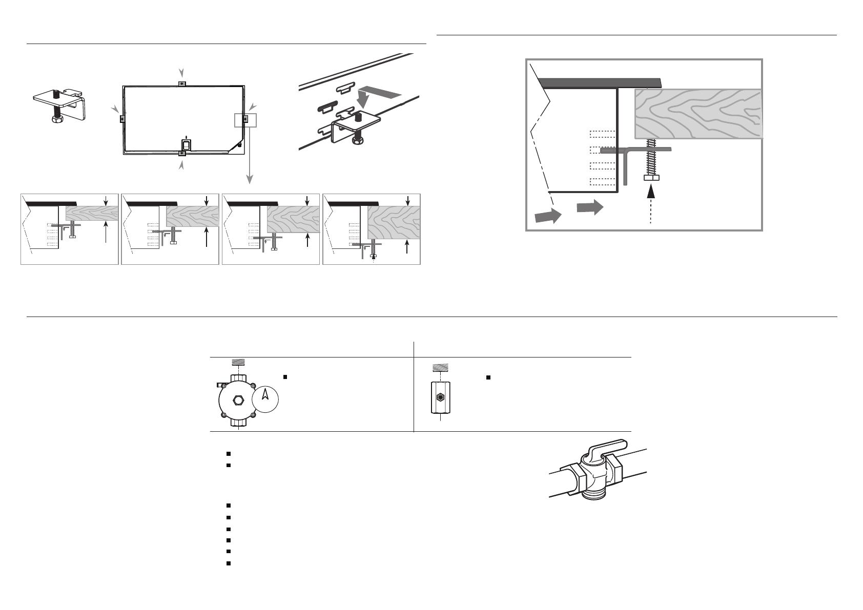
!0 FIT CLAMPING BRACKETS BASED ON THE
BENCHTOP THICKNESS !1 SECURE TO BENCHTOP
!2 CONNECT TO GAS SUPPLY
GAS
ON
GAS
ON
PTFE
⁄ NPT
500 mm
50 mm
1
2
500 mm
25 mm
25 mm
500 mm
NG
NG LPG
LPG
20-50 mm
½ “ BSP ½ “ BSP
x 4
1
1
2
2
16-20mm 20-30mm
Fibre washer
Floating nut Elbow (½ BSP external thread)
LPG test point adaptor (if using LPG)
min
S
A
R
min
A
F
S
REAR CLAMPS FRONT CLAMPS
40 mm
40 mm
30 mm
30 mm
30 mm
30 mm
Foam Tape
Adhesive side
Fibre washer
Floating nut Elbow (½ BSP external thread)
NG Models
ALL Models
Make sure the connection point will be accessible with the cooktop installed.
To enable the gas supply to be readily shut o by the customer, make sure the connection
is tted with an isolating valve close to the cooktop.
Make sure to t the supplied
washer and regulator.
Adjust to obtain a test point
pressure of 1 kPa with the two
semi-rapid burners operating at
highest setting.
Ensure the hose is long enough to allow for removal of cooktop for servicing.
Make sure the connector is located as shown in step 3 CLEARANCE DIMENSIONS.
The hose assembly must be AS/NZS 1869 Class B or D certied, with an Rp ½” (ISO 71) female thread connection.
The hose assembly must be as short as practicable and comply with relevant AS 5601/NZS 5261 requirements.
The hose must not be kinked, subjected to abrasion or permanently deformed.
The hose must not be near or in contact with any hot surfaces
(e.g. base of metal hotlplate, ue, or chassis of underbench oven etc.)
If connecting the gas with a exible hose:
LPG Models
check all connections
Make sure to t the supplied
washer and test point adaptor.
Make sure the supply pressure
is regulated to 2.75 kPa, with
the two semi-rapid burners
operating at highest setting.
Washer Washer
yellow tiplifting o
good ame
Arrow
x 4
x 4
30-40mm 40mm+
16-20mm 20-30mm
x 4
30-40mm 40mm+
view from below
GAS
ON
GAS
ON
PTFE
⁄ NPT
500 mm
50 mm
1
2
500 mm
25 mm
25 mm
500 mm
NG
NG LPG
LPG
20-50 mm
½ “ BSP ½ “ BSP
x 4
1
1
2
2
16-20mm 20-30mm
Fibre washer
Floating nut Elbow (½ BSP external thread)
LPG test point adaptor (if using LPG)
min
S
A
R
min
A
F
S
REAR CLAMPS FRONT CLAMPS
40 mm
40 mm
30 mm
30 mm
30 mm
30 mm
Foam Tape
Adhesive side
Ensure edge of tape
lines up with outer
edge of cooktop
Fibre washer
Floating nut Elbow (½ BSP external thread)
NG Models
ALL Models
Make sure the connection point will be accessible with the cooktop installed.
To enable the gas supply to be readily shut o by the customer, make sure the connection
is tted with an isolating valve close to the cooktop.
Make sure to t the supplied
washer and regulator.
Adjust to obtain a test point
pressure of 1 kPa with the two
semi-rapid burners operating at
highest setting.
Ensure the hose is long enough to allow for removal of cooktop for servicing.
Make sure the connector is located as shown in step 3 CLEARANCE DIMENSIONS.
The hose assembly must be AS/NZS 1869 Class B or D certied, with an Rp ½” (ISO 71) female thread connection.
The hose assembly must be as short as practicable and comply with relevant AS 5601/NZS 5261 requirements.
The hose must not be kinked, subjected to abrasion or permanently deformed.
The hose must not be near or in contact with any hot surfaces
(e.g. base of metal hotlplate, ue, or chassis of underbench oven etc.)
If connecting the gas with a exible hose:
LPG Models
check all connections
Make sure to t the supplied
washer and test point adaptor.
Make sure the supply pressure
is regulated to 2.75 kPa, with
the two semi-rapid burners
operating at highest setting.
Washer Washer
yellow tiplifting o
good ame
Arrow
x 4
x 4
30-40mm 40mm+
Repeat on all the other sides
GAS
ON
GAS
ON
1
2
Fibre washer
Floating nut Elbow (½ BSP external thread)
Foam Tape
Adhesive side
20 mm
50 mm
+50 mm
NG
ALL Models
Make sure the connection point will be accessible with the cooktop installed.
To enable the gas supply to be readily shut o by the customer, make sure
the connection is fitted with an isolating valve close to the cooktop.
Adjust to obtain a test point
pressure of 20 mbar with all
the burners operating at
highest setting.
Ensure the hose is long enough to allow for removal of cooktop for servicing.
Make sure the connector is located as shown in step 5 CLEARANCE DIMENSIONS.
Hose assembly must be AS/NZS 1869 Class B or D certified, with an Rp ½” (ISO 71) female thread connection.
Hose assembly must be as short as practicable and comply with relevant AS 5601/NZS 5261 requirements.
Hose must not be kinked, subjected to abrasion or permanently deformed.
Hose must not be near or in contact with any hot surfaces
(e.g. base of metal hotlplate, flue, or chassis of underbench oven etc.)
If connecting the gas with a flexible hose:
LPG
recessed to 50 mm
check all connections
Make sure the supply pressure
is regulated to 29 mbar, with
all the burners operating at
highest setting.
If converting to LPG, see 16 'Converting to a dierent gas type'
To check that the ignition system operates correctly, light each burner by itself, then all burners in combination.
Check for a well‐dened blue ame without any yellow tipping.
If any abnormality is evident, check that the components of the burner assembly are located properly
If proper operation cannot be obtained, contact your nearest F&P Authorised Service Centre.
The cooktop must not be used by the customer until proper operation has been achieved.
yellow tiplifting o
good ame
Arrow
10
!3 LEAK TESTING
GAS
ON
GAS
ON
1
2
Fibre washer
Floating nut Elbow (½ BSP external thread)
Foam Tape
Adhesive side
20 mm
50 mm
+50 mm
NG Models
ALL Models
Make sure the connection point will be accessible with the cooktop installed.
To enable the gas supply to be readily shut o by the customer, make sure the connection
is tted with an isolating valve close to the cooktop.
Make sure to t the supplied
regulator.
Adjust to obtain a test point
pressure of 1 kPa with all
burners operating at
highest setting.
Ensure the hose is long enough to allow for removal of cooktop for servicing.
Make sure the connector is located as shown in step 5 CLEARANCE DIMENSIONS.
The hose assembly must be AS/NZS 1869 Class B or D certied, with an Rp ½” (ISO 7‐1) female thread connection.
The hose assembly must be no longer than 1.2 m in length with minimum internal
diameter of 10 mm and comply with relevant AS 5601/NZS 5261 requirements.
The hose must not be kinked, subjected to abrasion or permanently deformed.
The hose must not be near or in contact with any hot surfaces
(e.g. base of metal hotlplate, ue, or chassis of underbench oven etc.)
If connecting the gas with a exible hose:
LPG Models
recessed to 50 mm
check all connections
Make sure to t the supplied
test point adaptor.
Make sure the supply pressure
is regulated to 2.75 kPa, with all
burners operating at highest
setting.
To check that the ignition system operates correctly, light each burner by itself, then all burners in combination.
Check for a well‐dened blue ame without any yellow tipping.
If any abnormality is evident, check that the components of the burner assembly are located properly
If proper operation cannot be obtained, contact your nearest F&P Authorised Service Centre.
The cooktop must not be used by the customer until proper operation has been achieved.
yellow tiplifting o
good ame
Arrow
Leak testing of the appliance shall be conducted according to the manufacturer’s instructions.
The appliance and its individual shut-off valve must be disconnected from the gas supply piping system during
any pressure testing of that system in excess of 3.5mbar.
Maximum inlet gas supply pressure 50 mbar.
After installing the gas supply and making all connections, check thoroughly for possible leaks:
1 Turn all control dials on unit to “OFF” position.
2 Open the valve on the gas supply.
3 Using a leak detection fluid, check each gas connection one at a time by spraying or brushing the solution over
the connection. The presence of bubbles will indicate a leak.
4 If necessary, tighten the fitting and recheck for leaks.
5 Turn on burner valve and light each burner.
6 Check for a clear blue flame without yellow tipping. If burners show any abnormalities, check that they are
located properly and in line with the injector.
11
INSTALLATION INSTRUCTIONS
!6 TEST OPERATION
!4 AFFIX DUPLICATE DATA LABEL SOMEWHERE
ACCESSIBLE & PLUG COOKTOP IN !5 FIT PAN SUPPORTS
Duplicate data label
Lifting off Yellow tip
Good flame
To check that the ignition system operates correctly, light each burner by itself, then all burners in combination.
Check for a well-defined blue flame without any yellow tipping.
If any abnormality is evident, check that the components of the burner assembly are located properly
If proper operation cannot be obtained, contact Customer Care or your nearest F&P Authorized Service Center.
The cooktop must not be used by the customer until proper operation has been achieved.
Note: pan supports may vary
Ensure the pan supports are located securely
and in the correct orientation (refer to User guide)
12
!7 FINAL CHECKLIST
TO BE COMPLETED BY THE INSTALLER
Have you installed the clamping brackets?
Have you verified that the type of model (factory-set for NG or LP) matches the type of gas at the site of installation?
Have you used the fibre washer supplied?
Have you sealed all connections with gas tape?
Have you leak-tested all connections?
Is the cooktop set to the correct working pressure?
Have you affixed the supplied duplicate data plate label on an adjacent
surface accessible to the customer?
Is the cooktop earthed?
Check that the power supply cord is NOT touching the cooktop.
OPERATION:
Do all burners ignite both individually and in combination?
Are the flames consistent and appropriately sized?
Have you demonstrated the basic operation to the customer?
Complete and keep for safe reference:
Model
Serial No.
Purchase Date
Purchaser
Dealer Address
Installer’s Name
Installer’s Signature
Installation Company
Installation Date
13
590877 A 11.15
www.fisherpaykel.com
Copyright © Fisher & Paykel Appliances 2015. All rights reserved.
The product specifications in this booklet apply to the specific products
and models described at the date of issue. Under our policy of continuous
product improvement, these specifications may change at any time. You
should therefore check with your Dealer to ensure this booklet correctly
describes the product currently available.
GB IE IN
  • Page 1 1
  • Page 2 2
  • Page 3 3
  • Page 4 4
  • Page 5 5
  • Page 6 6
  • Page 7 7
  • Page 8 8
  • Page 9 9
  • Page 10 10
  • Page 11 11
  • Page 12 12
  • Page 13 13
  • Page 14 14
  • Page 15 15
  • Page 16 16

Fisher & Paykel CG604DLPX1 Gas on Steel Hob User guide

Category
Cookers
Type
User guide
This manual is also suitable for

Ask a question and I''ll find the answer in the document

Finding information in a document is now easier with AI