Page is loading ...

INSTALLATION INSTRUCTIONS
LOK, LOR, LOS Series
FEATURES
• Universal input voltage range, AC single phase or DC input
• High efficiency
• Size (W/H/D): 38 x 90 x 114 mm
• Very high reliability, MTBF 1 600 000 h (GB, 40 °C)
INPUT DATA
• Operating input range: 85 – 264 VAC, 47 – 63 Hz
90 – 250 VDC
• Nominal input range: 100 – 240 VAC, 50 – 60 Hz
• Inrush current limitation by NTC (16 Ohm)
• Built-in input fuse in the input phase line (L ): 1.6 A, slow blow
OUTPUT DATA
FRONT-END
MODELS
V
o
[VDC]
I
o
[A]
P
o nom
[W]
LOK4001-2RLD 5.1 5.2 26
LOS4301-2 12 1.25 15
LOR4301-2 12 2.5 30
LOK4301-2R 12 4 48
LOS4601-2 24 0.65 15
LOR4601-2 24 1.25 30
LOK4601-2R 24 2 48
LOK4801-2R 48 1 48
BATTERY
CHARGERS
V
o
[VDC]
I
o
[A]
P
o nom
[W]
LOK4140-2RLD 13.6 3.6 49
LOK4240-2RLD 27.25 1.8 49
LOK4740-2RLD 54.5 0.9 49
• Linear output power derating down to 85% Po nom below 105 VAC
• Linear output power derating down to 45% Po nom at ambient
temperature above 50 °C up to 71 °C (LOK)
• Phase to phase connection at low mains (120 / 208 VAC) pro-
vides full output power (second fuse in the line to the N _
~ terminal
required = option F).
• Hold-up time 115 / 230 VAC at Po nom: 14 / 90 ms
• Output continuously no-load, overload and short-circuit proof
• Overload protection with self recovery (hiccup) or current limitation
(suffix L)
• Operation of several units in series possible
ELECTROMAGNETIC COMPATIBILITY
• Immunity according to IEC/EN 61000-4-2, -3, -4, -5, -6:
Electrostatic discharge (-4-2):
Electromagnetic field (-4-3):
Burst (-4-4):
Surges (-4-5):
Conducted immunity (-4-6):
level 2; 8 kV air (B)
level 2; 3 V/m (B)
level 3; 2 kVp (B)
level 3, line to PE: 2 kV (B)
level 2, line to line: 1 kV (B)
level 2; 3 VAC (A)
• Electromagnetic emissions, EN 55011, conducted (0.15 – 30 MHz):
Class B
ENVIRONMENTAL CONDITIONS
• Ambient operating temperature
T
a: -10 to 50 °C at free air
convection cooling
• Case temperature
T
c: -10 to 80 °C
• Storage temperature
T
s: -40 to 85 °C
• For use in environments pollution degree 2
• Damp heat steady state: 40 °C, 93%, 21 days
• Shock, bump and vibrations mounted on 35 mm DIN-rail:
- Shock: 15 gn, 11 ms, 18 bumps, 3 in each direction
- Bump: 10 gn, 11 ms, 6000 bumps, 1000 in each direction
- Vibration sinus: 10 – 60 Hz: 0.15 mm; 60 – 150 Hz: 2 gn
CONTROL FUNCTIONS
• LED Output OK
• Output voltage adjustment via R-pin: 90 – 110% Vo nom (suffix R)
• Output voltage OK signal (suffix D)
PROTECTION CIRCUITS
• Input surge and transient protection
OPTIONS
• F: (LOK only): Built-in second fuse in the input neutral line (N )
Caution: Double pole fusing!
• K: System connectors fitted with screw-terminals for pre-assembling
TERMINAL ALLOCATION
• The terminal allocation is defined in table 1 and 2
SAFETY AND INSTALLATION INSTRUCTIONS
• Class I equipment according to IEC/EN 62368-1
• Overvoltage category II
• 1.5 kVAC input/PE electric strength test voltage
• Safety approved to IEC/EN 62368-1, IEC 60950-1, UL/CSA 60950-1
• ES1 outputs according to IEC/EN 62368-1
• Degree of protection: IP 20
• Built-in device for vertical mounting on a DIN-rail
• Cage-clamp terminals (standard)
• Self-cooling; no forced cooling required
• Minimum space to next device:
– Top/bottom: 30 mm; left/right: 10 mm
– DIN-rail surface to converter front side: 110 mm
• Use proper tool (e.g. 3 mm screw driver) and adequate force for
dismounting the unit
WARNINGS
• Installation must strictly follow the national safety regulations.
• Switch off the system, before connecting the converter!
• A second fuse should be installed in the wiring to the input neutral
line N _
~(or use LOK models with option F), provided that:
– Local requirements demand an individual fuse in each source line.
– Phase and neutral lines of the mains are not defined.
• Only qualified personnel are allowed to work around or on the
equipment.
• Failure to properly install and maintain this equipment may result in
failure, severe personal injury, or substantial damage to property.
• Hazardous voltages are present, when connected to the mains.
• Do not open this apparatus!
• Safe operation of this equipment depends upon proper handling,
installation, and correct operation.
15 seconds
CAUTION – High voltage: Turn off the power supply
before disconnecting any terminal. Discharge the power
terminals or wait 15 seconds before servicing. Do not
turn on when any terminal is not connected.
ATTENTION – Haute tension : éteindre le l’alimentation avant de
déconnecter toute borne. Décharger les bornes d’alimentation ou
patienter 15 sec. avant toute réparation. Ne pas mettre l’alimentation
en marche lorsqu’aucune borne n’est connectée.
WEIGHT
• LOK: 0.35 kg, LOR: 0.27 kg, LOS: 0.23 kg
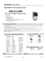
DIMENSIONS
• See fig. 1.
Figure 1.
113.6 (4.47")
90 (3.54") 38 (1.5")
108 (4.25")
T
c
T
c
LED
European
Projection
BWM20008-G_AG 31 Mar 2022
belfuse.com/power-solutions
UL/CSA 60950-1 1 LOK UL 508
1

INSTALLATION INSTRUCTIONS
LOK, LOR, LOS Series
CONNECTOR PIN ALLOCATION
13
2
L
N
Figure 2. Input Terminals
PIN NO. ELECTRICAL
DETERMINATION PIN DESIGNATION
1 Input phase line L
~
2 Protective earth PE
3 Input neutral line N
~
Table 1. Input
DC input connections:
• Unearthed battery or earthed negative pole:
Connect + to 1 (L )
Connect – to 3 (N )
• Earthed positive pole
Connect – to 1 (L )
Connect + to 3 (N )
46 8
57
Figure 3. Output Terminals
PIN NO. ELECTRICAL
DETERMINATION PIN DESIGNATION
4 D, Output positive D / +
5 Output positive +
6 Output negative -
7 Output negative -
8 R-input, not connected R / n.c.
Table 2. Output
10073
Figure 4. Snap-fit mounting to DIN-rail
10072
Figure 5. Dismounting from DIN-rail. Use proper tool
(min. 3 mm screw driver) and adequate force.
1
2
3
10074
Figure 6. Cage clamp terminals (standard).
Use 0.5 to 2.5 mm
2
(AWG 20 to 12) solid wires or stranded wires,
depending on local requirements.
OPTION K
System connectors fitted with screw-terminals allow for the use of
preassembled harnesses.
Option K is UL-approved for currents up to 10 A.
Section of solid wires: 1.5 mm2 (AWG 14),
Section of stranded wires: 1 mm2 (AWG 16)
IMPORTANT NOTE ON CE MARK
Bel Power Solutions power supplies are components only and
are intended for inclusion within other equipment by professional
installers. They are not intended for stand alone use.
The EMC behaviour is described in our data sheet. This data
provide the necessary basis for establishing the conformity
declaration by the OEM.
BWM20008-G_AG 31 Mar 2022
belfuse.com/power-solutions
UL/CSA 60950-1 1 LOK UL 508
1
Manufacturer
Bel Fuse Inc.
206 Van Vorst St.
Jersey City
NJ 07302, USA
/