

CE350 / CE370 User Manual
ii
EMC Information
FEDERAL COMMUNICATIONS COMMISSION INTERFERENCE
STATEMENT: This equipment has been tested and found to comply with the
limits for a Class A digital device, pursuant to Part 15 of the FCC Rules. These
limits are designed to provide reasonable protection against harmful
interference when the equipment is operated in a commercial environment.
This equipment generates, uses, and can radiate radio frequency energy and, if
not installed and used in accordance with the instruction manual, may cause
harmful interference to radio communications. Operation of this equipment in
a residential area is likely to cause harmful interference in which case the user
will be required to correct the interference at his own expense.
The device complies with Part 15 of the FCC Rules. Operation is subject to the
following two conditions: (1) this device may not cause harmful interference,
and (2) this device must accept any interference received, including
interference that may cause undesired operation.
FCC Caution: Any changes or modifications not expressly approved by the
party responsible for compliance could void the user's authority to operate this
equipment.
CE Warning: This is a class A product. In a domestic environment this
product may cause radio interference in which case the user may be required to
take adequate measures.
KCC Statement
유선 제품용 /A급 기기 (업무용 방송 통신 기기 )
이 기기는 업무용 (A 급)전자파적합기기로서 판매자 또는 사용자는 이
점을 주의하시기 바라며 ,가정 외의 지역에서 사용하는 것을 목적으로
합니다 .
RoHS
This product is RoHS compliant.

CE350 / CE370 User Manual
iii
SJ/T 11364-2006
The following contains information that relates to China.

CE350 / CE370 User Manual
iv
User Information
Online Registration
Be sure to register your product at our online support center:
Telephone Support
For telephone support, call one of the numbers below:
User Notice
All information, documentation, and specifications contained in this manual
are subject to change without prior notification by the manufacturer. The
manufacturer makes no representations or warranties, either expressed or
implied, with respect to the contents hereof and specifically disclaims any
warranties as to merchantability or fitness for any particular purpose. Any of
the manufacturer's software described in this manual is sold or licensed as is.
Should the programs prove defective following their purchase, the buyer (and
not the manufacturer, its distributor, or its dealer), assumes the entire cost of all
necessary servicing, repair and any incidental or consequential damages
resulting from any defect in the software.
The manufacturer of this system is not responsible for any radio and/or TV
interference caused by unauthorized modifications to this device. It is the
responsibility of the user to correct such interference.
The manufacturer is not responsible for any damage incurred in the operation
of this system if the correct operational voltage setting was not selected prior
to operation. PLEASE VERIFY THAT THE VOLTAGE SETTING IS
CORRECT BEFORE USE.
International http://support.aten.com
North America http://www.aten-usa.com/product_registration
International 886-2-8692-6959
China 86-10-5255-0110
Japan 81-3-5615-5811
Korea 82-2-467-6789
North America 1-888-999-ATEN ext 4988
United Kingdom 44-8-4481-58923

CE350 / CE370 User Manual
v
Package Contents
The CE350 / CE370 package consists of:
1 CE350L or CE370L PS/2 KVM Extender (Local Unit)
1 CE350R or CE370RQ PS/2 KVM Extender (Remote Unit)
1 Custom PS/2 KVM Cable Set (1.8 m)
2 Power Adapters
1 Mounting Kit
1 User Instructions*
Check to make sure that all the components are present and that nothing got
damaged in shipping. If you encounter a problem, contact your dealer.
Read this manual thoroughly and follow the installation and operation
procedures carefully to prevent any damage to the unit, and/or any of the
devices connected to it.
*Features may have been added to the CE350 / CE370 since this manual was
printed. Please visit our website to download the most up-to-date version of
the manual.
© Copyright 2015 ATEN® International Co., Ltd.
Manual Part No. PAPE-0328-AT1G
Manual Date: 2015-04-22
ATEN and the ATEN logo are registered trademarks of ATEN International Co., Ltd. All rights reserved.
All other brand names and trademarks are the registered property of their respective owners.

CE350 / CE370 User Manual
vi
Contents
EMC Information. . . . . . . . . . . . . . . . . . . . . . . . . . . . . . . . . . . . . . . . . . . . . ii
RoHS . . . . . . . . . . . . . . . . . . . . . . . . . . . . . . . . . . . . . . . . . . . . . . . . . . . . . ii
SJ/T 11364-2006 . . . . . . . . . . . . . . . . . . . . . . . . . . . . . . . . . . . . . . . . . . . .iii
User Information. . . . . . . . . . . . . . . . . . . . . . . . . . . . . . . . . . . . . . . . . . . . .iv
Online Registration . . . . . . . . . . . . . . . . . . . . . . . . . . . . . . . . . . . . . . . .iv
Telephone Support . . . . . . . . . . . . . . . . . . . . . . . . . . . . . . . . . . . . . . . .iv
User Notice . . . . . . . . . . . . . . . . . . . . . . . . . . . . . . . . . . . . . . . . . . . . . .iv
Package Contents . . . . . . . . . . . . . . . . . . . . . . . . . . . . . . . . . . . . . . . . . . . v
About this Manual. . . . . . . . . . . . . . . . . . . . . . . . . . . . . . . . . . . . . . . . . . .viii
Conventions . . . . . . . . . . . . . . . . . . . . . . . . . . . . . . . . . . . . . . . . . . . . . . . .ix
Product Information . . . . . . . . . . . . . . . . . . . . . . . . . . . . . . . . . . . . . . . . . .ix
Chapter 1.
Introduction
Overview. . . . . . . . . . . . . . . . . . . . . . . . . . . . . . . . . . . . . . . . . . . . . . . . . . .1
Features . . . . . . . . . . . . . . . . . . . . . . . . . . . . . . . . . . . . . . . . . . . . . . . . . . .3
Requirements . . . . . . . . . . . . . . . . . . . . . . . . . . . . . . . . . . . . . . . . . . . . . . . 4
Consoles. . . . . . . . . . . . . . . . . . . . . . . . . . . . . . . . . . . . . . . . . . . . . . . .4
Computers. . . . . . . . . . . . . . . . . . . . . . . . . . . . . . . . . . . . . . . . . . . . . . .4
Cables. . . . . . . . . . . . . . . . . . . . . . . . . . . . . . . . . . . . . . . . . . . . . . . . . .4
Operating Systems . . . . . . . . . . . . . . . . . . . . . . . . . . . . . . . . . . . . . . . . 5
Components . . . . . . . . . . . . . . . . . . . . . . . . . . . . . . . . . . . . . . . . . . . . . . . .6
CE350L / CE370L (Local Units) Front View . . . . . . . . . . . . . . . . . . . . . 6
CE350R (Remote Unit) Front View. . . . . . . . . . . . . . . . . . . . . . . . . . . .7
CE370RQ (Remote Unit) Front View . . . . . . . . . . . . . . . . . . . . . . . . . .8
Rear View . . . . . . . . . . . . . . . . . . . . . . . . . . . . . . . . . . . . . . . . . . . . . . . 9
Side View . . . . . . . . . . . . . . . . . . . . . . . . . . . . . . . . . . . . . . . . . . . . . . .9
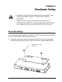
Chapter 2.
Hardware Setup
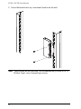
Rack Mounting . . . . . . . . . . . . . . . . . . . . . . . . . . . . . . . . . . . . . . . . . . . . .11
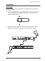
Installation. . . . . . . . . . . . . . . . . . . . . . . . . . . . . . . . . . . . . . . . . . . . . . . . .13
Grounding . . . . . . . . . . . . . . . . . . . . . . . . . . . . . . . . . . . . . . . . . . . . . .13
Setting Up . . . . . . . . . . . . . . . . . . . . . . . . . . . . . . . . . . . . . . . . . . . . . . 15
Installation Diagrams. . . . . . . . . . . . . . . . . . . . . . . . . . . . . . . . . . . . . . 16
Chapter 3.
Operation
Operating Modes . . . . . . . . . . . . . . . . . . . . . . . . . . . . . . . . . . . . . . . . . . . 19
Mode Selection. . . . . . . . . . . . . . . . . . . . . . . . . . . . . . . . . . . . . . . . . . . . .20
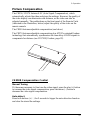
Picture Compensation . . . . . . . . . . . . . . . . . . . . . . . . . . . . . . . . . . . . . . .21
CE350R Compensation Control . . . . . . . . . . . . . . . . . . . . . . . . . . . . . 21
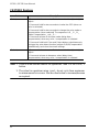
CE370RQ Deskew . . . . . . . . . . . . . . . . . . . . . . . . . . . . . . . . . . . . . . .22
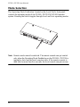
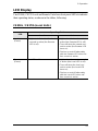
LED Display . . . . . . . . . . . . . . . . . . . . . . . . . . . . . . . . . . . . . . . . . . . . . . .23
CE350L / CE370L(Local Units). . . . . . . . . . . . . . . . . . . . . . . . . . . . . . 23

CE350 / CE370 User Manual
vii
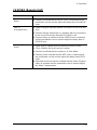
CE350R (Remote Unit) . . . . . . . . . . . . . . . . . . . . . . . . . . . . . . . . . . . .24
CE370RQ (Remote Unit). . . . . . . . . . . . . . . . . . . . . . . . . . . . . . . . . . .25
Appendix
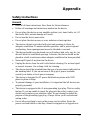
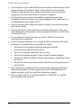
Safety Instructions. . . . . . . . . . . . . . . . . . . . . . . . . . . . . . . . . . . . . . . . . . .27
General . . . . . . . . . . . . . . . . . . . . . . . . . . . . . . . . . . . . . . . . . . . . . . . .27
Rack Mounting . . . . . . . . . . . . . . . . . . . . . . . . . . . . . . . . . . . . . . . . . .29
Technical Support. . . . . . . . . . . . . . . . . . . . . . . . . . . . . . . . . . . . . . . . . . .30
International. . . . . . . . . . . . . . . . . . . . . . . . . . . . . . . . . . . . . . . . . . . . .30
North America . . . . . . . . . . . . . . . . . . . . . . . . . . . . . . . . . . . . . . . . . . .30
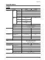
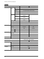
Specifications . . . . . . . . . . . . . . . . . . . . . . . . . . . . . . . . . . . . . . . . . . . . . .31
CE350 . . . . . . . . . . . . . . . . . . . . . . . . . . . . . . . . . . . . . . . . . . . . . . . . .31
CE370 . . . . . . . . . . . . . . . . . . . . . . . . . . . . . . . . . . . . . . . . . . . . . . . . .32
Troubleshooting . . . . . . . . . . . . . . . . . . . . . . . . . . . . . . . . . . . . . . . . . . . .33
About SPHD Connectors . . . . . . . . . . . . . . . . . . . . . . . . . . . . . . . . . . . . .34
Limited Warranty. . . . . . . . . . . . . . . . . . . . . . . . . . . . . . . . . . . . . . . . . . . .34

CE350 / CE370 User Manual
viii
About this Manual
This User Manual is provided to help you get the most from your system. It
covers all aspects of installation, configuration and operation. An overview of
the information found in the manual is provided below.
Chapter 1, Introduction, introduces you to the CE350 / CE370 system. Its
purpose, features and benefits are presented, and its front and back panel
components are described.
Chapter 2, Hardware Setup, describes the steps that are necessary to
quickly and safely set up your installation.
Chapter 3, Operation, explains the fundamental concepts involved in
operating the CE350 / CE370.
An Appendix, provides specifications and other technical information
regarding the CE350 / CE370.

CE350 / CE370 User Manual
ix
Conventions
This manual uses the following conventions:
Product Information
For information about all ATEN products and how they can help you connect
without limits, visit ATEN on the Web or contact an ATEN Authorized
Reseller. Visit ATEN on the Web for a list of locations and telephone numbers:
Monospaced Indicates text that you should key in.
[ ] Indicates keys you should press. For example, [Enter] means to
press the Enter key. If keys need to be chorded, they appear
together in the same bracket with a plus sign between them:
[Ctrl+Alt].
1. Numbered lists represent procedures with sequential steps.
♦Bullet lists provide information, but do not involve sequential steps.
→Indicates selecting the option (on a menu or dialog box, for
example), that comes next. For example, Start → Run means to
open the Start menu, and then select Run.
Indicates critical information.
International http://www.aten.com
North America http://www.aten-usa.com

CE350 / CE370 User Manual
x
This Page Intentionally Left Blank

1
Chapter 1
Introduction
Overview
The CE350 / CE370 is a PS/2 based KVM Extender with automatic signal
compensation and RS-232 serial functionality allow access to a computer
system from a remote PS/2 console (PS/2 keyboard, monitor, and PS/2 mouse).
Because it allows access to a computer system from a remote console, the
CE350 / CE370 is perfect for use in any type of installation where you need to
place the console where it is conveniently accessible, but you want the system
equipment to reside in a safe location – away from the dust and dirt of the
factory floor, or the harsh environmental influence of a construction site, for
example. This allows users to deploy system equipment over large distances.
To ensure the highest quality video, the CE350 features adjustable gain control,
while the CE370’s automatic delay line synchronizing function (ATEN patent)
corrects RGB color phase and timing errors that occur over long distance
transmissions. This also enables you to manually tune the R/G/B signal
settings, store the settings and retrieve them later using the memory button.
The CE350 / CE370 is also useful for control and security purposes, where you
can have the system unit in a secure area at the same time that you put the
console in the most convenient location for user access. This is ideal for
managing highly confidential data systems.
The CE350 / CE370 improves on previous designs by: 1) featuring Automatic
Signal Control (ASC); 2) the addition of an RS-232 port, on both the Local and
Remote Units – the RS-232 port on the Local Unit allows you to connect to a
serial terminal for configuration, while the RS-232 port on the Remote Unit
allows you to connect serial devices such as touchscreens and barcode
scanners; 3) the addition of a dedicated KVM port section on the Local Unit so
you can simply and easily include a KVM switch in your installation; 4) using
inexpensive Cat 5e cable instead of bulkier, more expensive, standard cables,
for a much neater, more convenient, more reliable data transfer connection; 5)
its ability to sense the distance to the system and automatically adjust the gain
accordingly; and 6) featuring a custom ASIC to ensure the utmost in reliability
and compatibility.
(Continues on next page.)

CE350 / CE370 User Manual
2
(Continued from previous page.)
Further CE350 / CE370 key features are built-in 8KV/15KV ESD protection
and 2KV surge protection, and color adjust picture compensation pushbuttons
on the Remote Unit to adjust the picture on the remote console. Remote video
is adjusted automatically and the settings are saved.
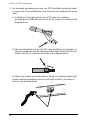
Setup is as easy as can be – simply connect the computer system box and local
console to the Local Unit (CE350L / CE370L); run the Cat 5e cable up to 300
meters to the Remote Unit (CE350R / CE370RQ); and plug the remote console
into the Remote Unit.

1. Introduction
3
Features
Local and Remote Units connect at distances up to 300 m using Cat 5e
cable
Deskew Function (CE370 only) – automatically synchronizes the time
delay of RGB signals to compensate for distance
On Screen Display (CE370 only) – conveniently adjust video quality with
the intuitive OSD menu system
Adjustable gain control – automatically and manually adjust signal
strength to compensate for distance
Dual console operation – control your system from both the local and
remote keyboard, monitor, and mouse consoles
Built-in ASIC for greater reliability and compatibility
Auto Signal Compensation (ASC) and storage of settings
RS-232 serial ports – connect to a serial terminal, or serial devices such as
touchscreens and barcode scanners (Baud Rate 115200 bps)
Audio Enabled – supports stereo speakers and microphone
Pushbutton operating mode selection (Local Unit only) – select between
Local and Auto operating modes, with the press of a single button
Built-in 8KV/15KV ESD protection (Contact voltage 8KV; Air voltage
15KV) and 2KV surge protection
High resolution video – up to 1920 x 1200@60Hz (150 m); 1280 x
1024@60Hz (300 m) (CE370)
Superior Audio – no loss in audio quality at 300 m
Supports Wide Screen formats
Supports VGA, SVGA, SXGA (1280 x 1024), UXGA (1600 x 1200),
WUXGA (1920 x 1200) and multisync monitors; local monitor supports
DDC; DDC2; DDC2B
Hot pluggable
Rack mountable
Easy to install – no software required – connecting cables to the devices is
all it takes

CE350 / CE370 User Manual
4
Requirements
Consoles
A VGA, SVGA, SXGA, UXGA, WUXGA, or multisync monitor capable
of the highest resolution you will be using on any computer in the
installation.
Note: If you connect a DDC type monitor to the Local Unit, the monitor
that connects to the Remote Unit must be able to support the highest
video resolution that the DDC monitor can provide
A PS/2 keyboard
A PS/2 mouse
Stereo microphone and stereo speakers (optional)
Computers
The following equipment must be installed on each computer that is to be
connected to the system:
A VGA, SVGA, SXGA, UXGA, WUXGA, or multisync card
A 6-pin Mini-DIN (PS/2) mouse port
A 6-pin Mini-DIN (PS/2) keyboard port
Microphone and speaker ports (optional)
Cables
For optimal signal integrity, and to simplify the layout, we strongly
recommend that you use the high quality custom KVM Cable that is
provided with this package.
Cat 5e cable is required to connect the Local and Remote CE350 / CE370
Units. Cable of a lower standard will result in degrading of the video
signal. We strongly recommend Cat 5e cable.
Maximum Cable Distances
Connection Distance
Computer to Local Unit (CE350L / CE370L) 10 m
Local Unit to Remote Unit (CE350R) 150 m
Local Unit to Remote Unit (CE370RQ) 300 m
Remote Unit (CE350R / CE370RQ) to monitor 20 m

1. Introduction
5
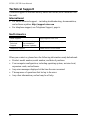
Operating Systems
Supported operating systems are shown in the table, below:
OS Version
Windows 2000, 2003, 2008, XP, Vista, 7
Linux RedHat 9.0 and higher
SuSE 10 / 11.1 and higher
Debian 3.1 / 4.0
Ubuntu 7.04 / 7.10
UNIX FreeBSD 5.5 / 6.1 / 6.2
Novell Netware 6.0 and higher

CE350 / CE370 User Manual
6
Components
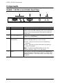
CE350L / CE370L (Local Units) Front View
No. Component Description
1 KVM Port Section If you are combining the CE350 / CE370 with a KVM
switch, the PS/2 KVM cable that links to the respective
ports on the Console section of the switch plugs into
these ports.
2 RS-232 Serial Port This RS-232 serial port is for connecting to a serial
terminal for configuration.
3 Operating Mode
Pushbutton This pushbutton toggles between the Operating
Modes available from the Local Console:
Local – only the Local Console can control the
system(s).
Auto – both the Local and Remote Consoles can
control the system.
Note: The default operating mode is Auto. See
Operating Modes, page 19, for full details.
4 LEDs The CE350L / CE370L has two LEDs to indicate the
operating status of the Local (CE350L / CE370L) and
Remote (CE350R / CE370RQ) Units. See page 23 for
full details.
1234

1. Introduction
7
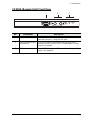
CE350R (Remote Unit) Front View
No. Component Description
1 RS-232 Serial Port RS-232 serial devices – such as touchscreens or
barcode scanners – plug into this port.
2 Picture Compensation
Pushbuttons These pushbuttons adjust the video quality of the
remote console. See CE350R Compensation Control,
page 21 for details.
3 LEDs The CE350R has three LEDs to indicate the operating
status. See page 24.
123

CE350 / CE370 User Manual
8
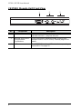
CE370RQ (Remote Unit) Front View
No. Component Description
1 RS-232 Serial Port RS-232 serial devices – such as touchscreens or
barcode scanners – plug into this port.
2 Deskew and Picture
Compensation
Pushbuttons
These pushbuttons adjust the video quality of the
remote console. See CE370RQ Deskew, page 22 for
details.
3 LEDs The CE370RQ has three LEDs to indicate operating
status/RGB. See page 25.
123

1. Introduction
9
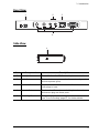
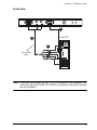
Rear View
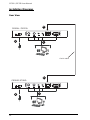
Side View
No. Component Description
1 Power Jack The cable from the DC Power adapter connects here.
2 Audio Ports These mini stereo ports are for the speakers (green)
and microphone (pink).
3 Remote I/O The Cat 5e cable that connects the Remote and Local
Units plugs in here.
4 Console Ports The Local and Remote console’s keyboard, monitor,
and mouse plug into these ports.
5 Grounding Terminal The grounding wire (used to ground the unit) attaches
here. See Grounding, page 13, for further details.
13
2
4
5

CE350 / CE370 User Manual
10
This Page Intentionally Left Blank
Page is loading ...
Page is loading ...
Page is loading ...
Page is loading ...
Page is loading ...
Page is loading ...
Page is loading ...
Page is loading ...
Page is loading ...
Page is loading ...
Page is loading ...
Page is loading ...
Page is loading ...
Page is loading ...
Page is loading ...
Page is loading ...
Page is loading ...
Page is loading ...
Page is loading ...
Page is loading ...
Page is loading ...
Page is loading ...
Page is loading ...
Page is loading ...
-
 1
1
-
 2
2
-
 3
3
-
 4
4
-
 5
5
-
 6
6
-
 7
7
-
 8
8
-
 9
9
-
 10
10
-
 11
11
-
 12
12
-
 13
13
-
 14
14
-
 15
15
-
 16
16
-
 17
17
-
 18
18
-
 19
19
-
 20
20
-
 21
21
-
 22
22
-
 23
23
-
 24
24
-
 25
25
-
 26
26
-
 27
27
-
 28
28
-
 29
29
-
 30
30
-
 31
31
-
 32
32
-
 33
33
-
 34
34
-
 35
35
-
 36
36
-
 37
37
-
 38
38
-
 39
39
-
 40
40
-
 41
41
-
 42
42
-
 43
43
-
 44
44


Ask a question and I''ll find the answer in the document
Finding information in a document is now easier with AI