Page is loading ...

CUSTOMER
SUPPORT
INFORMATION
Order toll-free in the U.S. 24 hours, 7 A.M. Monday to midnight Friday: 877-877-BBOX
FREE technical support, 24 hours a day, 7 days a week: Call 724-746-5500 or fax 724-746-0746
Mail order: Black Box Corporation, 1000 Park Drive, Lawrence, PA 15055-1018
Web site: www.blackbox.com • E-mail: [email protected]
FEBRUARY 2000
PCD50A
PCD50AE
PCD51A
PCD51AE
A/C-7P RO
A/C-7S RO
SW2
Host
Line
Sync
1 2 3 4 5 6 7 8
I
O
Printer
On
Line
Data
From
Host
Serial
Data
Out
Power
On
Off
A/C-7S RO
SW1
1 2 3 4 5 6 7 8
I
O
SW1
Host
Line
Sync
1 2 3 4 5 6 7 8
I
O
I
O
Printer
On
Line
Data
From
Host
Data
From
Parallel
Power
On
Off
A/C-7P RO

3
A/C-7P RO, A/C-7S RO
FEDERAL COMMUNICATIONS COMMISSION
AND
INDUSTRY CANADA
RADIO FREQUENCY INTERFERENCE STATEMENTS
This equipment generates, uses, and can radiate radio frequency energy
and if not installed and used properly, that is, in strict accordance with the
manufacturer’s instructions, may cause interference to radio communication.
It has been tested and found to comply with the limits for a Class A
computing device in accordance with the specifications in Subpart J of
Part 15 of FCC rules, which are designed to provide reasonable protection
against such interference when the equipment is operated in a commercial
environment. Operation of this equipment in a residential area is likely to
cause interference, in which case the user at his own expense will be required
to take whatever measures may be necessary to correct the interference.
Changes or modifications not expressly approved by the party responsible
for compliance could void the user’s authority to operate the equipment.
This digital apparatus does not exceed the Class A limits for radio noise emission from
digital apparatus set out in the Radio Interference Regulation of Industry Canada.
Le présent appareil numérique n’émet pas de bruits radioélectriques dépassant les limites
applicables aux appareils numériques de classe A prescrites dans le Règlement sur le
brouillage radioélectrique publié par Industrie Canada.

6
A/C-7P RO, A/C-7S RO
TRADEMARKS
Centronics
®
is a registered trademark of GENICOM Corporation.
Epson
®
is a registered trademark of Seiko Epson Corporation.
IBM
®
, Proprinter
®
, and IPDS
™
are registered trademarks or trademarks
of IBM Corporation.
Hewlett-Packard
®
, HP
®
, LaserJet
®
, and PCL
®
are registered trademarks
of Hewlett-Packard.
OKIDATA
®
is a registered trademark of Oki America, Inc.
Mannesmann Tally
®
is a registered trademark of Mannesmann Tally
Corporation.
All applied-for and registered trademarks are the property of their respective
owners.

7
A/C-7P RO, A/C-7S RO
Contents
Chapter Page
1. Specifications...................................................................................................9
2. Introduction ..................................................................................................10
2.1 Description of Front Panels .................................................................11
2.2 About this User’s Guide .......................................................................11
2.3 Unpacking.............................................................................................11
3. Installation.....................................................................................................13
Power On/Off Sequence ............................................................................15
4. Configuration................................................................................................20
4.1 A/C-7 RO Configuration .....................................................................20
4.2 Configuration Switch Settings .............................................................21
4.3 Setup Software (does not apply to versions after Feb. 1996).............26
4.4 Host/PC Download Command Overview...........................................27
4.5 Restoring Factory Defaults...................................................................57
5. Operation .....................................................................................................58
5.1 Printer Sharing .....................................................................................58
5.2 Parallel/Serial Port Initialization ........................................................59
5.3 Host Port Initialization.........................................................................59
5.4 Print Position and Page Length...........................................................59
5.5 Laser Printing .......................................................................................60
5.6 Computer Output Reduction (COR) .................................................61
5.7 Automatic Print Orientation (APO) ...................................................62
5.8 Generic Mode .......................................................................................64
6. Advanced Features ........................................................................................66
6.1 Command PassThru.............................................................................66
6.2 Custom User Strings.............................................................................67
6.3 SCS Mode Transparent Data ...............................................................67
6.4 Color Printing.......................................................................................68
6.5 Printing Bar Codes ...............................................................................68
6.6 I-O Graphics Language ........................................................................84
6.6.1 I-O Graphics Language Overview .............................................84
6.6.2 Helpful Hints..............................................................................88
6.6.3 Basic Description........................................................................90

6.7 I-O Graphic Language (IOGL) in Action.........................................101
6.7.1 General Steps............................................................................101
6.7.2 Tutorial .....................................................................................101
6.7.3 X- and Y-Axes............................................................................105
6.8 Linking Graphical Output to a Host Application ............................106
6.9 Printing Images from the Host..........................................................107
7. Troubleshooting .........................................................................................109
7.1 Interface Self-Test...............................................................................109
7.2 EBCDIC Hex Dump ...........................................................................110
7.3 ASCII Hex Dump ...............................................................................111
7.4 Problem Resolution Guide ................................................................112
Appendix A: Font (FGID) Reference for HP LaserJet Printers ..................117
Appendix B: Character Sets...........................................................................141
Appendix C: Serial Port Pinnings .................................................................144
Appendix D: Parallel Port Pinnings..............................................................146
Appendix E: Transferring Power to Pin 18 ..................................................148
8
A/C-7P RO, A/C-7S RO

9
A/C-7P RO, A/C-7S RO
1. Specifications
Emulation—IBM
®
3812, 4214,
4224, 3287, 3262, and 3268
printers (non-IPDS)
Systems Supported—ASCII
printer, IBM
®
30XX, 43XX,
937X host, or 3174, 3274, or
3276 controller
Indicators—(5) LEDs: Power,
Host line, Sync, Printer Online,
Data from Host, Data Out
Connectors—PCD50A, PCD50AE:
(1) BNC, (1) DB25 female,
(1) 36-pin Centronics
®
;
PCD51A, PCD51AE: (1) BNC,
(1) DB25 female, (1) DB25 male
Power—9 VAC wallmount
transformer
Size—6.5"H x 2.1"W x 5.1"D
(16.5 x 5.3 x 13 cm)
Weight—3 lb. (1.4 kg)

10
A/C-7P RO, A/C-7S RO
2. Introduction
operating in PCL
®
mode, the A/C-7
RO allows Computer Output
Reduction (COR) and Automatic
Page Orientation (APO). In
addition, paper can be pulled from
several sources and a multitude of
fonts (printer-resident or from
optional cartridges) are supported.
The A/C-7P RO comes with a
standard parallel sharing port that
allows automatic sharing of the
attached printer between the host
and a PC or LAN. The A/C-7S RO
comes with a standard serial sharing
port.
The A/C-7P RO and the AC-7S RO
are powerful, yet easy-to-operate
external printer interfaces. You can
easily set them up through on-board
configuration switches or Host/PC
download commands.
The A/C-7P RO and A/C-7S RO
attach virtually any ASCII printer to
an IBM 30XX, 43XX, 937X host, or
3174, 3274 or 3276 controller. They
offer reliable emulations of IBM
3812, 4214, 4224, 3287, 3262 and
3268 printers (all non-IPDS™).
When connected to a laser printer
SW1
I
O
I
O
OFF
ON
Power
A/C-7P RO
Printer
On
Line
Data
From
Host
Host
Line
Sync
Data
From
Parallel
1 2 3 4 5 6 7 8
SW1 SW2
I
O
I
O
OFF
ON
Power
A/C-7S RO
Printer
On
Line
Data
From
Host
Host
Line
Sync
Serial
Data
Out
1 2 3 4 5 6 7 8 1 2 3 4 5 6 7 8
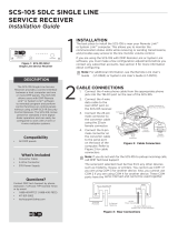
Figure 2-1. Front Panels of the A/C-7 RO.

11
A/C-7P RO, A/C-7S RO
2.1 Description of Front Panels
C
ONFIGURATION
S
WITCHES
The Configuration Switches are used
to set the output protocol and to
perform the available test and
diagnostic functions. While the A/C-
7P RO models come with only one
bank of switches, the A/C-7S RO
comes with two banks of eight
switches. The left bank is labeled
SW1; the right bank is labeled SW2.
LED
S
The green LED lights indicate the
following:
• Host Line Sync—Communication
lines between the host and the
interface are established.
• Printer Online—The printer is
ready to receive data.
• Data From Host—The A/C-7 RO is
currently processing data
received from the coax host.
• Data From Parallel/Serial—The
A/C-7 RO is currently receiving
data from an attached PC or
LAN. PC download commands
are processed, other data is
transmitted to the printer.
• Power—The A/C-7 RO is
powered on.
On/Off Switch—The On/Off switch
is used to power on or power off the
A/C-7 RO. Use this switch when
asked to cycle power.
2.2 About This User’s Guide
Since this user’s guide covers two
A/C-7 RO models, including A/C-7P
RO and A/C-7S RO.
2.3 Unpacking
Check the packaging for water or
physical damage, and notify the
carrier immediately if there is any
damage.
Keep the original packaging in
case you need to move or ship the
A/C-7 RO.

12
A/C-7P RO, A/C-7S RO
The package should include the
following:
• A/C-7P RO or A/C-7S RO
• Wallmount transformer (9V AC
output)
• Standard parallel cable (for
A/C-7P RO only)
• Standard serial cable (for
A/C-7S RO only)

13
A/C-7P RO, A/C-7S RO
3. Installation
4. If the sharing port of the A/C-7P
RO is used, attach the parallel
cable now. Note that a PC or
LAN connected to the A/C-7P
RO’s sharing port should always
be powered up when the A/C-7P
RO is operating.
5. Connect the wall mount
transformer from the outlet to
the A/C-7P RO’s “9V”
connector. Connect the power
cord(s) to the printer and PC (if
used).
6. Power on the A/C-7P RO, then
printer. The A/C-7P RO’s green
LED lights labeled “Power” and
“Printer On Line” should be lit.
7. Print an A/C-7P RO self-test.
Power off the A/C-7P RO. Set
configuration switch SW1:8 (far
right) to the “|” position. Power
on the A/C-7P RO. After the
self-test prints, set configuration
switch SW1:8 back to the “o”
position, then cycle the power
one more time.
8. Refer to the self-test printouts
to determine which
configuration parameters need
to be altered. Change these
parameters by using the
Host/PC download commands.
9. With the A/C-7P RO powered
off, attach the coax cable from
the host to the A/C-7P RO’s
BNC connector.
Before connecting the A/C-7 RO to
the printer, verify that the printer
functions properly by performing a
printer self-test. Consult the printer’s
user’s guide for instructions on how
to start and evaluate the self-test. If
the printer functions properly,
proceed with the installation of the
A/C-7 RO.
WARNING
Electrical current from power
lines and cables connecting
the A/C-7 RO, printer, and PC
can be hazardous. To
minimize the danger, follow
the instructions below.
NOTE
Do not connect the interface
to the coax cable until Step
9.
To install the A/C-7P RO:
1. Power off the printer and PC (if
used) and disconnect the power
cord(s).
2. Use the configuration switches
located on the A/C-7P RO’s
front panel to select the desired
output protocol. Refer to Table
4.1 for configuration switch
settings.
3. Connect the parallel cable from
the interface’s “Parallel Out”
connector to the printer’s
parallel port.

14
A/C-7P RO, A/C-7S RO
NOTE
Whenever the printer is
powered off, the A/C-7P RO
must also be powered off to
ensure they stay in sync with
each other.
To install the A/C-7S RO:
1. Power off the printer and PC (if
used) and disconnect the power
cord(s).
2. Use the configuration switches
on the A/C-7S RO’s front panel
to select the desired output
protocol and the serial output
parameters for the interface.
Refer to Tables 4.1 and 4.5 for
configuration switch settings.
3. Connect the serial cable from
the A/C-7S RO’s “Serial Out”
connector to the printer’s serial
port.
4. If the sharing port is used, attach
a second serial cable to the A/C-
7S RO’s “Serial In” port. Note
that a PC or LAN connected to
the A/C-7S’s sharing port should
always be powered on when the
A/C-7S RO is operating. In
addition, the PC/LAN and the
interface must be using the same
serial parameters. Refer to
Section 5.1, Printer Sharing, for
more information.
5. Connect the wall mount
transformer from the outlet to
the A/C-7S RO’s “9V”
connector. Connect the power
cord(s) to the printer and PC (if
used).
6. Power on the A/C-7S RO, then
the printer. The A/C-7S RO’s
green LED lights labeled
“Power” and “Printer On Line”
should be on. If the sharing port
is used and handshaking
requirements are met, the LED
labeled “PC/LAN Ready” should
also be on.
7. Print an A/C-7S RO self-test.
Power off the interface, then set
configuration switch SW1:8 (far
right on the first switch bank) to
the “|” position. (If you are
operating a label printer, put the
printer in ASCII hex dump
mode, then power on the A/C-
7S RO. If the label printer starts
printing, the A/C-7S RO has
passed the self-test. To obtain a
printout of the current settings,
connect the A/C-7S RO to a
laser or dot-matrix printer.)
Power on the A/C-7S RO. After
the self-test prints, set
configuration switch SW1:8 back
to the “o” position, then cycle
the power one more time.
8. Refer to the self-test printouts to
determine which configuration
parameters need to be altered.
Change these parameters by
using the Host/PC download
commands. Refer Chapter 4 for
further information.

15
A/C-7P RO, A/C-7S RO
9. With the A/C-7S RO powered
off, attach the coax cable from
the host to the A/C-7S RO’s
BNC connector.
NOTE
Whenever the printer is
powered off, the A/C-7S RO
must also be powered off to
ensure they stay in sync with
each other.
The self-test printouts in Figures 3-
1 and 3-2 show the default settings
for the different A/C-7 RO models.
The printout you obtain may differ
from the samples, since only the
configuration parameters associated
with the active output protocol (e.g.
HP PCL, IBM PPDS, etc.) are
printed. The second page of the self-
test printout is the same for both
A/C-7 RO models.
P
OWER
-O
N
/O
FF
S
EQUENCE
Follow the power-on and -off
sequences exactly, or the print
output may be garbled.
To power on:
1. Turn on the printer.
2. Turn on the A/C-7 RO.
To power off:
1. Turn off the A/C-7 RO.
2. Turn off the printer.

16
A/C-7P RO, A/C-7S RO
Self-Test Printout - A/C-7P RO
PARALLEL 3270 COAX INTERFACE
COPYRIGHT (c) 1994 SDE Corp
Rom Ok
Ram Ok
Software Version 1.00
ASCII Printer Protocol : Generic
#01 - Buffer Size (Characters) : 2 1920
#02 - Lines Density (LPI) : 6
#03 - Characters Density (CPI) : 10
#04 - Line Spacing : 1 Single (6 or 8 LPI)
#05 - Form Length (MPL) : 066
#06 - Maximum Print Position (MPP) : 080
#07 - Print Case : 1 Dual
#08 - LU1 Language : 01 English (US)
#12 - FF Before Local Screen Copy : 0 No
#13 - FF After Local Screen Copy: 0 No
#14 - LU3 Print Image (Non-SCS Mode): 0 LU3 and Local Copy
Null line suppress
#15 - CR at MPP + 1 : 0 Next line
#16 - NL at MPP +1 : 0 Current line + 2
#17 - Valid FF Followed by Data : 0 2nd PP
#18 - Valid FF at End of Buffer : 1 Line 1
#19 - FF Valid Location : 0 FF valid at 1st PP or MPP+1
#20 - Auto Function at End of Job : 0 NL
#21 - Print Quality (Fast Draft) : 0 DP=Fast Draft, Text= Draft
#25 - IBM Motion Command : 0 Use FF
#26 - Suppress Empty Forms : 0 No
#27 - Form Feed After Time Out : 0 No
#30 - Override of Formatting Cmds : 0 Disabled
#31 - Truncate/Wrap select : Wrap text beyond MPP
#34 - Interv Required (IR) Timeout : 120 times 5 seconds
#36 - Suppress IBM Control Codes : 0 No control codes suppressed
#37 - Vertical Channel Select (VCS) : 1 3268/4224
#39 - CPT End Delimiter (ASCII) : 2625 (&%)
#40 - CPT Start Delimiter (ASCII) : 2625 (&%)
#41 - Command ID Char (ASCII) : 5A (Z)
#42 - Start/Stop Buffer Hex Dump : 0 No Action
#45 - SCS TRN Translate : 1 3287 emulation, SCS code 35
#50 - Sharing Port Timeout : 08 Seconds
#51 - Host Port Timeout : 08 Seconds
#65 - Character Set Selection : 1 Roman 8
#56 - Parallel Port Init String :
SP:
#57 - Host Port Init String :
HP
Figure 3-1. Self-Test Printout for A/C-7P RO.

17
A/C-7P RO, A/C-7S RO
Self-Test Printout - A/C-7S RO
SERIAL 3270 COAX INTERFACE
COPYRIGHT (c) 1994 SDE Corp
Rom Ok
Ram Ok
Software Version 1.00
ASCII Printer Protocol : Generic
Serial Out Baud Rate : 9600 Baud
Serial Out Parity : None
Serial Out Word Length : 8 Bits
Serial Out Stop Bits : 1 Bit
#01 - Buffer Size (Characters) : 2 1920
#02 - Lines Density (LPI) : 6
#03 - Characters Density (CPI) : 10
#04 - Line Spacing : 1 Single (6 or 8 LPI)
#05 - Form Length (MPL) : 066
#06 - Maximum Print Position (MPP) : 080
#07 - Print Case : 1 Dual
#08 - LU1 Language : 01 English (US)
#12 - FF Before Local Screen Copy : 0 No
#13 - FF After Local Screen Copy: 0 No
#14 - LU3 Print Image (Non-SCS Mode) : 0 LU3 and Local Copy Null
line suppress
#15 - CR at MPP + 1 : 0 Next line
#16 - NL at MPP +1 : 0 Current line + 2
#17 - Valid FF Followed by Data : 0 2nd PP
#18 - Valid FF at End of Buffer : 1 Line 1
#19 - FF Valid Location : 0 FF valid at 1st PP or MPP+1
#20 - Auto Function at End of Job : 0 NL
#21 - Print Quality (Fast Draft) : 0 DP=Fast Draft, Text=Draft
#25 - IBM Motion Command : 0 Use FF
#26 - Suppress Empty Forms : 0 No
#27 - Form Feed After Time Out : 0 No
#30 - Override of Formatting Cmds : 0 Disabled
#31 - Truncate/Wrap select : Wrap text beyond MPP
#34 - Interv Required (IR) Timeout : 120 times 5 seconds
#36 - Suppress IBM Control Codes : 0 No control codes suppressed
#37 - Vertical Channel Select (VCS) : 1 3268/4224
#39 - CPT End Delimiter (ASCII) : 2625 (&%)
#40 - CPT Start Delimiter (ASCII) : 2625 (&%)
#41 - Command ID Char (ASCII) : 5A (Z)
#42 - Start/Stop Buffer Hex Dump : 0 No Action
#45 - SCS TRN Translate : 1 3287 emulation, SCS code35
#50 - Sharing Port Timeout : 08 Seconds
#51 - Host Port Timeout : 08 Seconds
Figure 3-2. Self-Test Printout for A/C-7S RO.

18
A/C-7P RO, A/C-7S RO
#65 - Character Set Selection : 1 Roman 8
#76 - Serial In Baud Rate : 2 9600 Baud
#77 - Serial In Word Length : 8 Bits
#78 - Serial In Stop Bits : 1 Bit
#79 - Serial In Parity : 0 None
#56 - Parallel Port Init String:
SP:
#57 - Host Port Init String:
HP:
Figure 3-2. Self-Test Printout for A/C-7S RO, Page 1 (continued).

19
A/C-7P RO, A/C-7S RO
Figure 3-3. Self-Test Printout, Page 2.
SCS (LU1) EBCDIC to ASCII Translate Table
40 50 60 70 80 90 A0 B0 C0 D0 E0 F0 456789ABCDEF
0 20 26 2D D6 D2 B3 F3 5E 7B 7D 5C 30 &–øØ°µ^{ } \ 0
1 20 C5 2F DC 61 6A 7E BB 41 4A 20 31 é / Éaj ~ £AJ 1
2 C0 C1 A2 A4 62 6B 73 BC 42 4B 53 32 âêÂÊbks¥BKS2
3 CC CD D8 A5 63 6C 74 F2 43 4C 54 33 äëÄËclt · CLT3
4 C8 C9 A1 A3 64 6D 75 BE 44 4D 55 34 àèÀÈdmuƒDMU4
5 C4 D5 E0 E5 65 6E 76 BD 45 4E 56 35 áíÁÍenv§ENV5
6 E2 D1 E1 A6 66 6F 77 F4 46 4F 57 36 ãîÃÎfow¶FOW6
7 D4 DD D0 A7 67 70 78 F7 47 50 58 37 åïÅÏgpx
1/4
GPX7
8 B5 D9 B4 E6 68 71 79 F8 48 51 59 38 çìÇÌhqy
1/2
HQY8
9 B7 DE B6 A9 69 72 7A F5 49 52 5A 39 ñßÑ`irz
3/4
IRZ9
A BF 21 7C 3A FB F9 B8 5B 2D 31 32 33 ¢ ! | : «ª ¡ [ –
123
B 2E 24 2C 23 FD FA B9 5D C2 C3 DF AE . $ ,#»º¿]ôûÔÛ
C 3C 2A 25 40 E4 D7 E3 B0 CE CF DA DB <*%@∂ æ D
–
öüÖÜ
D 28 29 5F 27 B2 20 B1 AB CA CB E8 AD ( ) _ ' y ,Y ¨òùÒÙ
E 2B 3B 3E 3D F0 D3 F1 27 C6 C7 E7 ED +;>= Æ ´óúÓÚ
F 7C 5E 3F 22 FE BA 20 5F EA EF E9 20 |^?"± _õÿÕ
´
´
EBCDIC
DSC (LU3) DBC to ASCII Translate Table
00 10 20 30 40 50 60 70 80 90 A0 B0 0123456789AB
0 00 20 30 26 C8 CC A1 D8 61 71 41 51 0&àäÀÄaqAQ
1 00 3D 31 2D C9 CD A3 A5 62 72 42 52 =1-èëÈËbrBR
2 00 27 32 2E D9 DD E6 A7 63 73 43 53 ' 2 . ìïÌÏcsCS
3 00 22 33 2C CA CE E8 DA 64 74 44 54 " 3 , òöÒÖdtDT
4 00 2F 34 3A CB CF AD DB 65 75 45 55 / 4 :ùüÙÜeuEU
5 00 5C 35 2B E2 C0 E1 A2 66 76 46 56 \5+ãâÃÂfvFV
6 00 7C 36 5E EA C1 E9 A4 67 77 47 57 |6^õêÕÊgwGW
7 007C37B0EFD159A668784858 |7
–
ÿîYÎhxHX
8 3E3F38B3C8C241DF69794959 >?8°àôAÔiyIY
9 3C 21 39 00 C9 C3 45 AE 6A 7A 4A 5A <!9 èûEÛjzJZ
A 5B 24 DE 5E C5 C4 45 E0 6B D7 4B D3 [$ß^éáEÁkæKÆ
B 5D BF BD 7E D9 C5 49 DC 6C D6 4C D2 ]¢§~ìéIÉløLØ
C 29 BB 23 AB CA D5 4F E5 6D D4 4D D0 )£#"òíOÍmåMÅ
D 28 BC 40 60 CB C6 55 E7 6E B5 4E B4 (¥@'ùóUÓnçNÇ
E 7D F2 25 A9 CF C7 59 ED 6F 3B 4F 3B }·%`üúYÚo;O;
F 7B BA 5F 00 B5 B7 43 B6 70 2A 50 2A { _ çñCÑp*P*
DBC

4. Configuration
20
A/C-7P RO, A/C-7S RO
4.1 A/C-7 RO Configuration
The A/C-7 RO can be configured
through its on-board configuration
switches or by sending download
commands from the host or from a
PC/LAN. To ensure proper
functioning of your A/C-7 RO, you
should review all available
parameters.

21
A/C-7P RO, A/C-7S RO
4.2 Configuration Switch Settings
Use the A/C-7 RO’s configuration
switches to select the output
protocol and to perform the
available test and diagnostic
functions. Use a pointed object, such
as a ball-point pen, to change the
switch settings.
When operating, the A/C-7 RO
will only recognize EBCDIC Hex
Dump and ASCII Dump settings. All
other settings are read only at power-
up. Whenever you change one of
these settings, remember to cycle the
power to activate them.
NOTE
If an invalid switch setting is
encountered at power-up, all
LED lights will blink and the
A/C-7 RO cannot operate.

22
A/C-7P RO, A/C-7S RO
Table 4-1. Configuration Switch Settings.
Output Protocol SW1:4 SW1:5 SW1:6 SW1:7
Hewlett-Packard
®
PCL o o | o
IBM Proprinter o | o |
IBM PPDS oooo
Epson ESC/P1 ooo|
Epson DFX+ o | | |
Epson LQ (24-pin) o | | o
Epson 9-pin (DFX) | o o o
Generic | o o |

23
A/C-7P RO, A/C-7S RO
Table 4-2. Tests/Diagnostic.
Tests/Diagnostic SW1:1 SW1:8
Restore Factory Defaults | o
Self-Test o |
EBCDIC Hex Dump o |
Table 4-3. Tests/Diagnostic.
Tests/Diagnostic SW1:4 SW1:5 SW1:6 SW1:7
ASCII Hex Dump ||||
Table 4-4. Operating Mode.
Operating Mode SW1:1 SW1:4 SW1:5 SW1:6 SW1:7 SW1:8
No Tests o Valid Output Protocol o
The first two test functions
(Restore Factory Defaults and Self-
Test) are performed only if the
configuration switches are set as
indicated when the A/C-7 RO is
powered on. In the case of the self-
test, the A/C-7 RO prints a self-test
at power-on and then needs to be
powered off. Refer to Chapter 7 for
more information.
/