Page is loading ...

332144C
EN
Instructions-Parts
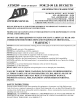
Reactor
®
E-10hp
For spraying or dispensing polyurea coatings and polyurethane foam. For professional
use only.
Not approved for use in explosive atmospheres or hazardous locations.
3000 psi (21 MPa, 207 bar) Maximum Working Pressure
Important Safety Instructions
Read all warnings and instructions in this
manual. Save these instructions.
ti21488a

2 332144C
Contents
Warnings . . . . . . . . . . . . . . . . . . . . . . . . . . . . . . . . . 3
Important Isocyanate (ISO) Information . . . . . . . . 6
Isocyanate Conditions . . . . . . . . . . . . . . . . . . . . 6
Material Self-ignition . . . . . . . . . . . . . . . . . . . . . . 6
Keep Components ISO and RES Separate . . . . 6
Moisture Sensitivity of Isocyanates . . . . . . . . . . . 6
Foam Resins with 245 fa Blowing Agents . . . . . . 6
Changing Materials . . . . . . . . . . . . . . . . . . . . . . . 7
Systems . . . . . . . . . . . . . . . . . . . . . . . . . . . . . . . . . . 8
Models . . . . . . . . . . . . . . . . . . . . . . . . . . . . . . . . . . . 8
Related Manuals . . . . . . . . . . . . . . . . . . . . . . . . . . . 9
Overview . . . . . . . . . . . . . . . . . . . . . . . . . . . . . . . . . 10
Component Identification . . . . . . . . . . . . . . . . . . . 11
Controls and Indicators . . . . . . . . . . . . . . . . . . . . 12
Heater Controls . . . . . . . . . . . . . . . . . . . . . . . . . 12
System Controls . . . . . . . . . . . . . . . . . . . . . . . . 12
Controls and Indicators . . . . . . . . . . . . . . . . . . . 13
Setup . . . . . . . . . . . . . . . . . . . . . . . . . . . . . . . . . . . . 15
Locate Reactor . . . . . . . . . . . . . . . . . . . . . . . . . 15
Electrical Requirements . . . . . . . . . . . . . . . . . . 15
Ground System . . . . . . . . . . . . . . . . . . . . . . . . . 16
Connect Fluid Hoses . . . . . . . . . . . . . . . . . . . . . 16
Connect Gun Air Hose . . . . . . . . . . . . . . . . . . . 16
Connect Main Air Supply . . . . . . . . . . . . . . . . . 16
Flush Before First Use . . . . . . . . . . . . . . . . . . . 16
Fill Wet-Cups . . . . . . . . . . . . . . . . . . . . . . . . . . 17
Fill Fluid Tanks . . . . . . . . . . . . . . . . . . . . . . . . . 17
Purge Air and Flush Fluid From Lines . . . . . . . 18
Startup . . . . . . . . . . . . . . . . . . . . . . . . . . . . . . . . . . 19
Heatup Guidelines . . . . . . . . . . . . . . . . . . . . . . 20
Heat Management Tips . . . . . . . . . . . . . . . . . . . 20
Spraying . . . . . . . . . . . . . . . . . . . . . . . . . . . . . . . . . 21
Pause . . . . . . . . . . . . . . . . . . . . . . . . . . . . . . . . . . . 22
Refill Tanks . . . . . . . . . . . . . . . . . . . . . . . . . . . . . . 22
Pressure Relief Procedure . . . . . . . . . . . . . . . . . . 23
Shutdown . . . . . . . . . . . . . . . . . . . . . . . . . . . . . . . . 23
Maintenance . . . . . . . . . . . . . . . . . . . . . . . . . . . . . . 24
Flushing . . . . . . . . . . . . . . . . . . . . . . . . . . . . . . . . . 25
Purge Hoses . . . . . . . . . . . . . . . . . . . . . . . . . . . 26
Troubleshooting . . . . . . . . . . . . . . . . . . . . . . . . . . . 27
Pump Control Status Codes . . . . . . . . . . . . . . . 27
DIP Switch Settings . . . . . . . . . . . . . . . . . . . . . . 29
Heat Control Diagnostic Codes . . . . . . . . . . . . . 31
Reactor Electronics . . . . . . . . . . . . . . . . . . . . . . 33
Heaters . . . . . . . . . . . . . . . . . . . . . . . . . . . . . . . 35
Proportioner . . . . . . . . . . . . . . . . . . . . . . . . . . . . 36
Repair . . . . . . . . . . . . . . . . . . . . . . . . . . . . . . . . . . . 39
Before Beginning Repair . . . . . . . . . . . . . . . . . . 39
Remove Supply Tank . . . . . . . . . . . . . . . . . . . . 39
Replace Recirc/Spray Valves . . . . . . . . . . . . . . 40
Displacement Pump . . . . . . . . . . . . . . . . . . . . . 41
Control Panel . . . . . . . . . . . . . . . . . . . . . . . . . . . 42
Motor Control . . . . . . . . . . . . . . . . . . . . . . . . . . . 44
Heater . . . . . . . . . . . . . . . . . . . . . . . . . . . . . . . . 48
Pressure Transducers . . . . . . . . . . . . . . . . . . . . 50
Drive Housing . . . . . . . . . . . . . . . . . . . . . . . . . . 51
Replace Cycle Counter Switch . . . . . . . . . . . . . 52
Electric Motor . . . . . . . . . . . . . . . . . . . . . . . . . . . 53
Motor Brushes . . . . . . . . . . . . . . . . . . . . . . . . . . 54
Fans . . . . . . . . . . . . . . . . . . . . . . . . . . . . . . . . . . 54
Tank Fluid Level Sensors . . . . . . . . . . . . . . . . . 55
Parts . . . . . . . . . . . . . . . . . . . . . . . . . . . . . . . . . . . . 57
System Packages . . . . . . . . . . . . . . . . . . . . . . . 57
E-10hp Proportioners . . . . . . . . . . . . . . . . . . . . 58
Suggested Replacement Parts . . . . . . . . . . . . . . . 74
Accessories . . . . . . . . . . . . . . . . . . . . . . . . . . . . . . 74
Dimensions . . . . . . . . . . . . . . . . . . . . . . . . . . . . . . . 74
Technical Data . . . . . . . . . . . . . . . . . . . . . . . . . . . . 75
Notes . . . . . . . . . . . . . . . . . . . . . . . . . . . . . . . . . . . . 77
Graco Standard Warranty . . . . . . . . . . . . . . . . . . . 78

Warnings
332144C 3
Warnings
The following warnings are for the setup, use, grounding, maintenance, and repair of this equipment. The exclama-
tion point symbol alerts you to a general warning and the hazard symbols refer to procedure-specific risks. When
these symbols appear in the body of this manual or on warning labels, refer back to these Warnings. Product-specific
hazard symbols and warnings not covered in this section may appear throughout the body of this manual where
applicable.
WARNING
ELECTRIC SHOCK HAZARD
This equipment must be grounded. Improper grounding, setup, or usage of the system can cause elec-
tric shock.
• Turn off and disconnect power cord before servicing equipment.
• Connect only to grounded electrical outlets.
• Use only 3-wire extension cords.
• Ensure ground prongs are intact on power and extension cords.
• Do not expose to rain. Store indoors.
TOXIC FLUID OR FUMES HAZARD
Toxic fluids or fumes can cause serious injury or death if splashed in the eyes or on skin, inhaled, or
swallowed.
• Read MSDSs to know the specific hazards of the fluids you are using.
• Store hazardous fluid in approved containers, and dispose of it according to applicable guidelines.
PERSONAL PROTECTIVE EQUIPMENT
Wear appropriate protective equipment when in the work area to help prevent serious injury, including
eye injury, hearing loss, inhalation of toxic fumes, and burns. This protective equipment includes but is
not limited to:
• Protective eyewear, and hearing protection.
• Respirators, protective clothing, and gloves as recommended by the fluid and solvent manufacturer.
SKIN INJECTION HAZARD
High-pressure fluid from gun, hose leaks, or ruptured components will pierce skin. This may look like just
a cut, but it is a serious injury that can result in amputation. Get immediate surgical treatment.
• Engage trigger lock when not spraying.
• Do not point gun at anyone or at any part of the body.
• Do not put your hand over the spray tip.
• Do not stop or deflect leaks with your hand, body, glove, or rag.
•Follow the Pressure Relief Procedure when you stop spraying and before cleaning, checking, or
servicing equipment.
• Tighten all fluid connections before operating the equipment.
• Check hoses and couplings daily. Replace worn or damaged parts immediately.

Warnings
4 332144C
FIRE AND EXPLOSION HAZARD
Flammable fumes, such as solvent and paint fumes, in work area can ignite or explode. To help prevent
fire and explosion:
• Use equipment only in well ventilated area.
• Eliminate all ignition sources; such as pilot lights, cigarettes, portable electric lamps, and plastic drop
cloths (potential static arc).
• Keep work area free of debris, including solvent, rags and gasoline.
• Do not plug or unplug power cords, or turn power or light switches on or off when flammable fumes
are present.
• Ground all equipment in the work area. See Grounding instructions.
• Use only grounded hoses.
• Hold gun firmly to side of grounded pail when triggering into pail. Do not use pail liners unless they
are antistatic or conductive.
• Stop operation immediately if static sparking occurs or you feel a shock. Do not use equipment
until you identify and correct the problem.
• Keep a working fire extinguisher in the work area.
THERMAL EXPANSION HAZARD
Fluids subjected to heat in confined spaces, including hoses, can create a rapid rise in pressure due to
the thermal expansion. Over-pressurization can result in equipment rupture and serious injury.
• Open a valve to relieve the fluid expansion during heating.
• Replace hoses proactively at regular intervals based on your operating conditions.
PRESSURIZED ALUMINUM PARTS HAZARD
Use of fluids that are incompatible with aluminum in pressurized equipment can cause serious chemical
reaction and equipment rupture. Failure to follow this warning can result in death, serious injury, or prop-
erty damage.
• Do not use 1,1,1-trichloroethane, methylene chloride, other halogenated hydrocarbon solvents or
fluids containing such solvents.
• Many other fluids may contain chemicals that can react with aluminum. Contact your material sup-
plier for compatibility.
WARNING

Warnings
332144C 5
EQUIPMENT MISUSE HAZARD
Misuse can cause death or serious injury.
• Do not operate the unit when fatigued or under the influence of drugs or alcohol.
• Do not exceed the maximum working pressure or temperature rating of the lowest rated system
component. See Technical Data in all equipment manuals.
• Use fluids and solvents that are compatible with equipment wetted parts. See Technical Data in all
equipment manuals. Read fluid and solvent manufacturer’s warnings. For complete information
about your material, request MSDS from distributor or retailer.
• Do not leave the work area while equipment is energized or under pressure.
• Turn off all equipment and follow the Pressure Relief Procedure when equipment is not in use.
• Check equipment daily. Repair or replace worn or damaged parts immediately with genuine manu-
facturer’s replacement parts only.
• Do not alter or modify equipment. Alterations or modifications may void agency approvals and create
safety hazards.
• Make sure all equipment is rated and approved for the environment in which you are using it.
• Use equipment only for its intended purpose. Call your distributor for information.
• Route hoses and cables away from traffic areas, sharp edges, moving parts, and hot surfaces.
• Do not kink or over bend hoses or use hoses to pull equipment.
• Keep children and animals away from work area.
• Comply with all applicable safety regulations.
MOVING PARTS HAZARD
Moving parts can pinch, cut or amputate fingers and other body parts.
• Keep clear of moving parts.
• Do not operate equipment with protective guards or covers removed.
• Pressurized equipment can start without warning. Before checking, moving, or servicing equipment,
follow the Pressure Relief Procedure and disconnect all power sources.
BURN HAZARD
Equipment surfaces and fluid that’s heated can become very hot during operation. To avoid severe
burns:
• Do not touch hot fluid or equipment.
WARNING

Important Isocyanate (ISO) Information
6 332144C
Important Isocyanate (ISO) Information
Isocyanates (ISO) are catalysts used in two component materials.
Isocyanate Conditions
Material Self-ignition
Keep Components ISO and RES
Separate
Moisture Sensitivity of
Isocyanates
Exposure to moisture (such as humidity) will cause ISO
to partially cure; forming small, hard, abrasive crystals,
which become suspended in the fluid. Eventually a film
will form on the surface and the ISO will begin to gel,
increasing in viscosity.
NOTE: The amount of film formation and rate of crystal-
lization varies depending on the blend of ISO, the
humidity, and the temperature.
Foam Resins with 245 fa
Blowing Agents
Some foam blowing agents will froth at temperatures
above 90°F (33°C) when not under pressure, especially
if agitated. To reduce frothing, minimize preheating in a
circulation system.
Spraying or dispensing materials containing isocya-
nates creates potentially harmful mists, vapors, and
atomized particulates.
Read material manufacturer’s warnings and material
MSDS to know specific hazards and precautions
related to isocyanates.
Prevent inhalation of isocyanate mists, vapors, and
atomized particulates by providing sufficient ventila-
tion in the work area. If sufficient ventilation is not
available, a supplied-air respirator is required for
everyone in the work area.
To prevent contact with isocyanates, appropriate per-
sonal protective equipment, including chemically
impermeable gloves, boots, aprons, and goggles, is
also required for everyone in the work area.
Some materials may become self-igniting if applied
too thick. Read material manufacturer’s warnings and
material MSDS.
Cross-contamination can result in cured material in
fluid lines which could cause serious injury or damage
equipment. To prevent cross-contamination:
• Never interchange ISO and RES wetted parts.
• Never use solvent on one side if it has been con-
taminated from the other side.
NOTICE
Partially cured ISO will reduce performance and the
life of all wetted parts.
• Always use a sealed container with a desiccant
dryer in the vent, or a nitrogen atmosphere. Never
store ISO in an open container.
• Keep the ISO pump wet cup or reservoir (if
installed) filled with appropriate lubricant. The
lubricant creates a barrier between the ISO and
the atmosphere.
• Use only moisture-proof hoses compatible with
ISO.
• Never use reclaimed solvents, which may contain
moisture. Always keep solvent containers closed
when not in use.
• Always lubricate threaded parts with an appropri-
ate lubricant when reassembling.

Important Isocyanate (ISO) Information
332144C 7
Changing Materials
NOTICE
Changing the material types used in your equipment
requires special attention to avoid equipment damage
and downtime.
• When changing materials, flush the equipment
multiple times to ensure it is thoroughly clean.
• Always clean the fluid inlet strainers after flushing.
• Check with your material manufacturer for chemi-
cal compatibility.
• When changing between epoxies and urethanes
or polyureas, disassemble and clean all fluid com-
ponents and change hoses. Epoxies often have
amines on the RES (hardener) side. Polyureas
often have amines on the RES (resin) side

Systems
8 332144C
Systems
Models
The model no., series letter, and serial no. are located on the back of the cart. For faster assistance, please have that
information ready before calling Customer Service.
* See page 15 for detailed electrical requirements.
Part
Maximum
Working
Pressure,
psi
(MPa, bar)
Volts
Proportioner
Model
Unheated
Hose
35 ft (10.6 m)
Cord
Adapter
Gun
Model Part
APT100
3000
(21, 207)
120 V 24T100 25R000 ---
Fusion
®
Air Purge
249810
P2T100
3000
(21, 207)
120 V 24T100 25R000 ---
PROBLER
®
P2
GCP2RA
APT900
3000
(21, 207)
230 V 24R900 25R000
North
America
Fusion
®
Air Purge
249810
APT901
3000
(21, 207)
230 V 24R900 25R000 Europe
Fusion
®
Air Purge
249810
APT902
3000
(21, 207)
230 V 24R900 25R000
Australia/
Asia
Fusion
®
Air Purge
249810
P2T900
3000
(21, 207)
230 V 24R900 25R000
North
America
PROBLER
®
P2
GCP2RA
P2T901
3000
(21, 207)
230 V 24R900 25R000 Europe
PROBLER
®
P2
GCP2RA
P2T902
3000
(21, 207)
230 V 24R900 25R000
Australia/
Asia
PROBLER
®
P2
GCP2RA
24T900
3000
(21, 207)
230 V 24R900 ---
North
America
--- ---
24T901
3000
(21, 207)
230 V 24R900 --- Europe --- ---
24T902
3000
(21, 207)
230 V 24R900 ---
Australia/
Asia
--- ---
Bare
Proportioner
Part, Series Volts
* Electrical
Connection
Maximum
Working
Pressure,
psi (MPa, bar) Approvals
24T100, A 120 V 20 A cord
(motor)
20 A cord
(heaters)
3000
(21, 207)
24R900, A 230 V 15 A cord
(motor)
15 A cord
(heaters)
3000
(21, 207)
9902471
Conforms to ANSI/UL
Std. 499 Certified to
CAN/CSA Std.
C22.2 No. 88

Related Manuals
332144C 9
Related Manuals
The following manuals are for Reactor E-10hp components and accessories. Some are supplied with your package,
depending on its configuration. Manuals are also available at www.graco.com.
Displacement Pump
Part No. Description
311076 Instruction-Parts Manual (English)
Fusion Air Purge Spray Gun
Part No. Description
309550 Instruction-Parts Manual (English)
Probler P2 Spray Gun
Part No. Description
313213 Instruction-Parts Manual (English)
Probler P2 Recirculation Kit
Part No. Description
406842 Instruction-Parts Manual (English)
Lift Ring Kit
Part No. Description
332977 Instruction-Parts Manual (English)

Overview
10 332144C
Overview
The Reactor E-10hp is a portable, electric-powered, 1:1
mix ratio proportioner for use with:
•Polyurea
• Polyurea hybrid coatings
• Polyurethane foam
Material may be applied with impingement mix spray
guns.
The Reactor E-10hp is gravity-fed from 6 gal. (22.7 liter)
supply tanks mounted on the unit.
Severe duty, positive displacement reciprocating piston
pumps meter fluid flow to the gun for mixing and apply-
ing. When set to recirculation mode, Reactor E-10hp will
circulate fluids back to the supply tanks.
The Reactor E-10hp uses primary heating rods and
boost heating rods, for each fluid, and an insulated hose
bundle with circulation return hoses. This allows the
hoses and gun to be preheated to the desired tempera-
ture before spraying. The boost heating rods are used
during circulation mode to reduce heatup time. Digital
displays show the temperatures of the two fluids.
Electronic controls monitor fluid pressures, drive the
motor, and alerts the operator if errors occur. See
Motor/Pump Status Codes, page 14, for further infor-
mation.
The Reactor E-10hp has two recirculation speeds, slow
and fast, and an adjustable pressure output.
Slow Recirculation
• Slow circulation results in a higher temperature
transfer in the heater, so hoses and gun heat up
quicker.
• Good for touchup or low flow spraying, up to moder-
ate temperature.
• Not used to circulate full tanks up to temperature.
• Use with 245 fa blowing agent foams, to minimize
heat returned to tank and reduce frothing.
Fast Recirculation
• Use to support higher flow rates or higher tempera-
tures by preheating the tanks.
• Agitates fluid within tanks, to avoid heating only the
fluid at the top of the tank.
• Use for flushing.
Pressure Adjust
Automatically maintains selected pressure output for
dispensing or spraying.

Component Identification
332144C 11
Component Identification
Key for F
IG
. 1
A Supply Tank (ISO)
B Supply Tank (RES)
CPump (ISO)
DPump (RES)
E Heater (under shroud)
F Fluid Pressure Gauges
G Recirc/Spray and Overpressure Relief Valves
H Tank Level Sensors (bottom of tanks)
J Control Panel; see F
IG
. 2, page 12
K Electric Motor and Drive Housings
L Insulated Hose Bundle (includes circulation return
hoses)
M Fusion Air Purge Spray Gun
N Desiccant Dryer
P Recirculation Tubes
Q Air Line Inlet (quick-disconnect fitting)
R Outlet Hose Connections
S Return Hose Connections
T Fluid Temperature Sensors (located on heater
assembly, under shroud)
U Hose Rack and Control Shield
V Fluid Inlet Ball Valves (each side)
W Fluid Inlet Strainers (each side)
X Power Cords (not shown)
Y Fluid Temperature Gauges (each side)
Z Air Filter/Moisture Separator
F
IG
. 1: Component Identification
A
B
C
D
F
G
J
P
U
V
Q
M
L
E
Z
P
S
W
K
R
R
S
G
H
Y
N
ti21488a

Controls and Indicators
12 332144C
Controls and Indicators
See Controls and Indicators identification table, page
13.
Heater Controls
System Controls
NOTICE
To prevent damage to soft key buttons, do not press
the buttons with sharp objects such as pens, plastic
cards, or fingernails.
F
IG
. 2. Heater Controls and Indicators
°
F
°
C
AE
AR
AF
AK
AJ
AA
AB
AC
AD
AM
AN
AS
AO
AP
AG
AH
AL
F
IG
. 3. System Controls and Indicators
-
-
STATUS
1
2
3
4
5
6
7
8
9
10
0
+
-
I I
+
-
AV
AT
AY
AU
AXAW

Controls and Indicators
332144C 13
Controls and Indicators
Key Name Description
Heater Controls
AA ISO Setpoint Increase Increases the temperature setpoint by one degree in the units selected
within the setpoint limits. Press target key prior to adjusting.
AB ISO Setpoint Decrease Decreases the temperature setpoint by one degree in the units
selected within the setpoint limits. Press target key prior to adjusting.
AC RES Setpoint Increase Increases the temperature setpoint by one degree in the units selected
within the setpoint limits. Press target key prior to adjusting.
AD RES Setpoint Decrease Decreases the temperature setpoint by one degree in the units
selected within the setpoint limits. Press target key prior to adjusting.
AE ISO Heater On/Off Key Turns heater on or off for ISO zone. Also clears heater zone diagnostic
codes, see page 31.
AF RES Heater On/Off Key Turns heater on or off for RES zone. Also clears heater zone diagnostic
codes, see page 31.
AG Actual Temperature Key Press to display actual temperature. Press and hold to display electrical
current.
AH Target Temperature Key Press to display target temperature. Press and hold to display heater
control circuit board temperature.
AJ Temperature Scale Key °F Press to change temperature scale to degrees Fahrenheit.
AK Temperature Scale Key °C Press to change temperature scale to degrees Celsius.
AL Temperature Display Show actual temperature or target temperature of heater zones,
depending on selected mode. Defaults to actual at startup. Range is
32-170°F (0-77°C) for ISO and RES.
Heater Indicators
AM ISO Heater Activity
LEDs flash when heater zones are on. The duration
of each flash shows the extent that the heater is
turned on.
AN RES Heater Activity
LEDs flash when heater zones are on. The duration
of each flash shows the extent that the heater is
turned on.
AO Actual Temperatures Active Actual temperatures are displayed.
AP Target Temperatures Active Target temperatures are displayed.
AR Fahrenheit Units Active Indicates that temperatures are displayed in °F.
AS Celsius Units Active Indicates that temperatures are displayed in °C.
System Controls
AT Heater Power Enables heater control. The switch includes a 20 A circuit breaker.
AU Motor Power Enables motor. The switch includes a 20 A circuit breaker.
AV Motor Pump Control Function Knob Selects operation mode / pressure setpoint. See Motor/Pump Control
Function Knob, page 14.
System Indicators
AW Boost Heat Indicator Indicates boost heat is active.
AX Tank Level Indicator See Tank Level Sensor LED, page 14.
AY System Status Indicator Flashes an error code if alarm or deviation is active. See Motor/Pump
Status Codes, page 14.

Controls and Indicators
14 332144C
Motor/Pump Control Function Knob
Use knob (AV) to select desired function
.
Motor/Pump Status Codes
If error occurs, status indicator (AY) will blink 1 to 19
times to indicate status code, pause, then repeat, or will
blink other active error codes. See T
ABLE
1 for a brief
description of status codes.
NOTE: The default is to shut down if a status code indi-
cation occurs.
Heater Control Diagnostic Codes
Heater control diagnostic codes appear on the tempera-
ture display. These alarms turn off heat.
Tank Level Sensor LED
The tank level sensor LED (AX) is triggered when chem-
ical is not present in either tank.
Icon Setting Function
Stop/Park
Stops motor and automati-
cally parks pumps.
Slow Recirc Slow recirculation speed.
Fast Recirc Fast recirculation speed.
Pressure
Adjust
Adjusts fluid pressure to
gun in spray mode.
Table 1: Motor/Pump Status Codes
No. Name
1 Pressure imbalance between ISO and RES sides
2 Pressure deviation from setpoint
3 Pressure transducer ISO failure
4 Pressure transducer RES failure
5 Excessive current draw
6 High motor temperature
7 No cycle counter switch input
8 High cycle rate deviation (more than 1.0 GPM)
High cycle rate shutdown (more than 1.1 GPM)
9 Low tank level
10 Not used
11 Locked motor rotor
12 Motor controller bus overvoltage
13 Motor controller bus undervoltage
14 Motor controller high temperature
15-19 Motor controller fault
Table 2: Heater Control Diagnostic Codes
Code Name Alarm Zone
01 High fluid temperature Individual
02 High zone current Individual
03 No zone current with heater on Individual
04 Thermocouple not connected Individual
05 High controller temperature Individual
06 No communications with zone
pod
Individual
09 Display is missing Individual
99 No communication with heater
control module
Individual
Table 3: Tank Level Indicator (AX)
Chemical Status
> 1 gallon Off
< 1 gallon Flashing

Setup
332144C 15
Setup
Locate Reactor
1. Locate Reactor on a level surface.
2. Do not expose Reactor to rain.
Electrical Requirements
1. Connect Reactor to the correct power source for
your model. See
Table 4
. Power cords must be con-
nected to two separate, dedicated circuits. See F
IG
.
4.
2. Some models include cord adapters for use outside
North America. Connect the appropriate adapter to
the unit’s power cord before connecting to your
power source.
NOTE: Cords must be 3-conductor grounded, rated for your environment.
Improper wiring may cause electric shock or other
serious injury if work is not performed properly. All
electrical wiring must be done by a qualified
electrician and comply with all local codes and
regulations.
To avoid electric shock, always unplug both cords
before servicing Reactor and wait one minute.
F
IG
. 4: Use Two Separate Circuits
1
1
Heater Power
Motor Power
2
Ensure no other high amp loads are connected while running
Reactor.
To verify separate circuits, plug in Reactor or a worklight and
cycle breakers on and off.
1
2
TI7061a
Table 4: Electrical Requirements
Model
Required Power
Source
Power Cord
Connectors Supplied Local Adapters
230 V, 1 phase, 50/60
Hz, two 15 ft (4.5 m)
power cords
Two separate, dedi-
cated circuits rated at
minimum of 15 A
each
120V, 50/60 Hz, two
15 ft (4.5 m) power
cords
Two separate dedi-
cated circuits rated at
minimum of 20 A
each
Table 5: Extension Cord Requirements
Model
Required Wire Size
Up to 50 ft (15 m) Up to 100 ft (30 m)
All models AWG 12 AWG 10
Two IEC 3-20 C20
Plugs
NEMA 6-15P
Euro CEE74
YP-39 AS3112
(North America)
(Europe)
(Australia/Asia)
Two NEMA
5-20P Plugs

Setup
16 332144C
Ground System
Reactor:
grounded through power cord.
Generator (if used):
follow your local code. Start and
stop generator with power cord(s) disconnected.
Spray gun:
grounded through the supplied fluid hoses,
connected to a properly grounded Reactor. Do not oper-
ate without at least one grounded fluid hose.
Object being sprayed:
follow your local code.
Solvent pails used when flushing:
follow your local
code. Use only metal pails, which are conductive,
placed on a grounded surface. Do not place pail on a
nonconductive surface, such as paper, plastic, or card-
board, which interrupts grounding continuity.
To maintain grounding continuity when flushing or
relieving pressure:
hold a metal part of spray gun
firmly to the side of a grounded
metal
pail, then trigger
gun.
Connect Fluid Hoses
1. Connect fluid supply hoses to outlet hose connec-
tions (R, F
IG
. 5). Red hoses for ISO, blue for RES.
Fittings are sized to prevent connection errors. Con-
nect other end of hoses to ISO and RES inputs of
gun.
NOTE: Probler guns use recirc accessory kit 24E727.
2. Connect recirculation hoses from gun recirculation
ports to connections (S).
Connect Gun Air Hose
1. Connect gun air hose to the gun air input and to the
air filter outlet (Z). If you are using more than one
hose bundle, join the air hoses with the nipple pro-
vided with the hose bundle.
2. On units with Fusion guns, connect the supplied ball
valve and quick-disconnect coupler to the gun air
hose, then connect the coupler to the gun air fitting.
Connect Main Air Supply
Connect the main air supply to the quick disconnect fit-
ting (Q) on the unit. Air supply hose must be at least
5/16 in. (8 mm) ID up to 50 ft (15 m) or 3/8 in. (10 mm)
ID up to 100 ft (30 m).
NOTE: Air Filter/Moisture Separator (Z) is equipped with
an automatic moisture drain.
Flush Before First Use
The Reactor is tested with a plasticizer oil at the factory.
Flush out the oil with a compatible solvent before spray-
ing. See Flushing, page 25.
The equipment must be grounded to reduce the risk
of static sparking and electric shock. Electric or static
sparking can cause fumes to ignite or explode.
Improper grounding can cause electric shock.
Grounding provides an escape wire for the electric
current.
F
IG
. 5
(RES)
(ISO)
Air
S
R
R
S

Setup
332144C 17
Fill Wet-Cups
Keep the felt washers in the pump wet-cups saturated
with Graco ISO pump oil, Part No. 217374. The lubricant
creates a barrier between the ISO and the atmosphere.
Fill wet-cups through slots in plate, or loosen screws
and swing plate aside.
Fill Fluid Tanks
NOTE: Using a drill and mixing blade, mix filled or sepa-
rated materials in the pail before adding to the tanks.
Material left in the tanks overnight may need to be
remixed in the tanks.
1. Lift hose rack. Remove tank cover and pour ISO
into tank (red side, with desiccant filter in cover).
Replace cover .
NOTE: Desiccant filter is blue when fresh, and turns
pink when saturated. Be sure shipping plugs are
removed from openings on desiccant filter.
2. Remove tank cover and pour resin into RES tank
(blue side). Replace cover .
Pump rod and connecting rod move during operation.
Moving parts can cause serious injury such as
pinching or amputation. Keep hands and fingers
away from wet-cup during operation. Shut off Motor
Power before filling wet-cup.
NOTICE
To prevent cross-contamination of fluids and equip-
ment parts, never interchange (isocyanate) and
(resin) parts or containers.
Have at least two 5 gal. (19 liter) pails to transfer fluid
from drums to supply tanks. Label one pail “ISO” and
the other “RES”, using the red and blue labels pro-
vided. Always double-check which material you have
before pouring it in the supply tanks. Pouring is easier
if pails are not filled to the top.
Open only one supply tank at a time, to avoid splash-
ing material from one tank into the other when filling.
1
Add thin coating of grease lubricant to tank o-ring
if lid is difficult to assemble to tank.
1
ISO
RES
1

Setup
18 332144C
Purge Air and Flush Fluid From
Lines
1. Remove both recirculation tubes (P) from the tanks
and secure each one in a dedicated waste con-
tainer.
2. Set function knob to Stop/Park .
3. Plug in power cords(s). See Table 2, page 15.
4. Open both pump fluid inlet valves (V, shown in open
position).
5. Turn on Motor Power. System status indicator (AY)
should turn on.
6. Set Recirc/Spray valves to Recirc.
7. Set function knob to Slow Recirc or Fast Recirc
.
8. When clean fluids exit both recirculation tubes (P),
set function knob to Stop/Park .
9. Replace recirculation tubes in supply tanks.
To avoid fire and explosion:
• Flush equipment only in a well-ventilated area.
• Ensure main power is off and heater is cool before
flushing.
• Do not turn on heater until fluid lines are clear of
solvent.
P
STATUS
1
2
3
4
5
6
7
8
9
10
0
+
-
V
ti21917a
ti21495a
-
STATUS
1
2
3
4
5
6
7
8
9
10
0
+
-
-
STATUS
1
2
3
4
5
6
7
8
9
10
0
+
-
OR
ti21489a
1
2
3
4
5
6
7
8
9
10
0
+
-
ti21490a

Startup
332144C 19
Startup
1. Perform Setup, page 15.
2. Set function knob to Slow Recirc or Fast Recirc
. See Heatup Guidelines, page 20, then con-
tinue with steps 3-6.
3. Turn on Heater Power.
4. Set temperatures:
a. Press or to change temperature
scale.
b. Press to display target temperatures.
c. To set heat zone target temperature,
press or until display shows
desired temperature. Repeat for zone.
d. Press to display actual temperatures.
5. Circulate through heater until temperature readouts
display desired temperature. See Table 6.
6. Adjust heat controls as necessary for a stable spray
temperature.
NOTE: Heatup times are based on 70°F (21°C) starting
material temperature and 70°F (21°C) ambient tempera-
ture.
NOTE: Different fluids will absorb heat at different rates.
When refilling a warm machine, heatup times will be
less.
Heated fluid can cause equipment surfaces to
become very hot. To avoid severe burns:
• Do not operate Reactor without all covers and
shrouds in place.
• Do not touch hot fluid or equipment.
• Allow equipment to cool completely before
touching it.
1
2
3
4
5
6
7
8
9
10
0
+
-
1
2
3
4
5
6
7
8
9
10
0
+
-
OR
ti21489a
°
F
°
C
Table 6: Approximate heatup time for starting a cold
machine with 5 gallons (19 liters) per side
Fluid Spray Target
Temperature
120 V 230 V
35 ft (10.7 m) Hose
(1 bundle)
125°F (52°C) 15 minutes 10 minutes
170°F (77°C) 40 minutes 20 minutes

Startup
20 332144C
Heatup Guidelines
The fluids must be circulated from the pumps through
the heater, hoses, and back to the tanks to ensure warm
fluids are supplied to the gun.
Slow Recirculation
• Slow Recirc results in a higher temperature transfer
in the heater, so hoses and gun heat up quicker.
• Good for touchup or low flow spraying, up to moder-
ate temperature.
Fast Recirculation
Fast Recirc keeps heaters on full-time to bring fluid
tanks up to temperature. The higher your flow rate, the
more heat needed in the tanks before spraying.
•
For 230 V systems:
Use Fast Recirc until pump inlet
fluid temperature gauges (Y) are within 45°F (25°C)
of target outlet temperature.
•
For 120 V systems:
Use Fast Recirc until pump inlet
fluid temperature gauges (Y) are within 30°F (17°C)
of target temperature.
•
Volume in tanks:
Use only what you need. For
example, 2.5 gal. (10 l) in each tank will heat up
almost twice as fast as 5 gal. (20 l).
• Mixes fluid within tanks, to avoid heating only the
fluid at the top of the tank.
• Use for flushing.
Heat Management Tips
• Heaters perform better with lower flow rates or
smaller mix modules.
• Triggering the gun for short periods helps maintain
efficient heat transfer, keeping material at the
desired temperature. Triggering the gun for a long
period may not allow enough heating time, depend-
ing on material temperature in tanks.
• If temperature displays fall below acceptable limits,
set function knob to Slow Recirculation and cir-
culate again to bring temperatures back up.
• Each 35 ft (10.7 m) hose bundle adds about 5 min-
utes to heatup time, with most materials. Maximum
recommended hose length is 105 ft (32 m).
• For a quicker start, do initial heatup circulation with
the tanks 1/4 to 1/3 filled, then add more material.
/