Page is loading ...

Instructions - Parts List
For spraying or dispensing 1:1 mix ratio materials, including epoxies,
polyurethane foam, polyurea coatings, and joint fill materials.
For professional use only.
Not approved for use in European explosive atmosphere locations.
See page 4 for a list of models and maximum working pressures.
Important Safety Instructions
Read all warnings and instructions in
this manual. Save these instructions.
WLD
WLD
Nonheated Package, MD2 Cold Spray Gun
Heated
Package, with
Fusion
™
Gun
311075U
EN

2 311075U
Contents
Related Manuals . . . . . . . . . . . . . . . . . . . . . . . . . . . 3
Systems . . . . . . . . . . . . . . . . . . . . . . . . . . . . . . . . . . 3
Models . . . . . . . . . . . . . . . . . . . . . . . . . . . . . . . . . . . 4
Warnings . . . . . . . . . . . . . . . . . . . . . . . . . . . . . . . . . 5
Overview . . . . . . . . . . . . . . . . . . . . . . . . . . . . . . . . . . 8
Isocyanate Hazard . . . . . . . . . . . . . . . . . . . . . . . . . . 9
Foam Self-ignition . . . . . . . . . . . . . . . . . . . . . . . . . . 9
Moisture Sensitivity of Isocyanates . . . . . . . . . . . . 9
Keep Components A and B Separate . . . . . . . . . 10
Changing Materials . . . . . . . . . . . . . . . . . . . . . . . . 10
Component Identification . . . . . . . . . . . . . . . . . . . 11
Controls and Indicators . . . . . . . . . . . . . . . . . . . . 13
Motor/Pump Control Function Knob . . . . . . . . . 13
STATUS Indicator . . . . . . . . . . . . . . . . . . . . . . . 13
Motor Power Switch/Circuit Breaker . . . . . . . . . 14
Heater Power Switch/Circuit Breaker . . . . . . . . 14
Heater Temperature Controls . . . . . . . . . . . . . . 14
Fluid Temperature Sensors and Displays . . . . . 14
Setup . . . . . . . . . . . . . . . . . . . . . . . . . . . . . . . . . . . . 15
Startup of Heated Units . . . . . . . . . . . . . . . . . . . . . 22
Heatup Guidelines . . . . . . . . . . . . . . . . . . . . . . 23
Heat Management Tips . . . . . . . . . . . . . . . . . . . 23
Heating Foam Resins with 245 fa Blowing Agents
24
Spraying/Dispensing . . . . . . . . . . . . . . . . . . . . . . . 25
Pause (Heated Units) . . . . . . . . . . . . . . . . . . . . . . . 26
Refilling Tanks . . . . . . . . . . . . . . . . . . . . . . . . . . . . 26
Pressure Relief Procedure . . . . . . . . . . . . . . . . . . 27
Shutdown . . . . . . . . . . . . . . . . . . . . . . . . . . . . . . . . 27
Maintenance . . . . . . . . . . . . . . . . . . . . . . . . . . . . . . 28
Flushing . . . . . . . . . . . . . . . . . . . . . . . . . . . . . . . . . 29
Troubleshooting . . . . . . . . . . . . . . . . . . . . . . . . . . 31
Status Codes . . . . . . . . . . . . . . . . . . . . . . . . . . 31
Troubleshooting Chart . . . . . . . . . . . . . . . . . . . 34
Repair . . . . . . . . . . . . . . . . . . . . . . . . . . . . . . . . . . . 39
Before Beginning Repair . . . . . . . . . . . . . . . . . . 39
Removing Supply Tanks . . . . . . . . . . . . . . . . . . 39
Recirc/Spray Valves . . . . . . . . . . . . . . . . . . . . . 40
Displacement Pump . . . . . . . . . . . . . . . . . . . . . 41
Control Module . . . . . . . . . . . . . . . . . . . . . . . . . 43
Fluid Heaters (if supplied) . . . . . . . . . . . . . . . . . 48
Pressure Transducers . . . . . . . . . . . . . . . . . . . . 48
Drive Housing . . . . . . . . . . . . . . . . . . . . . . . . . . 49
Cycle Counter Switch Replacement . . . . . . . . . 50
Electric Motor . . . . . . . . . . . . . . . . . . . . . . . . . . 51
Motor Brushes . . . . . . . . . . . . . . . . . . . . . . . . . . 52
Fan . . . . . . . . . . . . . . . . . . . . . . . . . . . . . . . . . . 52
Parts . . . . . . . . . . . . . . . . . . . . . . . . . . . . . . . . . . . . 54
Suggested Spare Replacement Parts . . . . . . . . . 68
Accessories . . . . . . . . . . . . . . . . . . . . . . . . . . . . . . 68
Dimensions . . . . . . . . . . . . . . . . . . . . . . . . . . . . . . . 69
Technical Data . . . . . . . . . . . . . . . . . . . . . . . . . . . . 70
Graco Standard Warranty . . . . . . . . . . . . . . . . . . . 72
Graco Information . . . . . . . . . . . . . . . . . . . . . . . . . 72

Related Manuals
311075U 3
Related Manuals
The following manuals are for Reactor E-10 components and accessories. Some are supplied with your package,
depending on its configuration. Manuals are also available at www.graco.com.
68
Systems
Displacement Pump
Part No. Description
311076 Instruction-Parts Manual (English)
Fluid Heater
Part No. Description
311210 Instruction-Parts Manual (English)
Fusion Air Purge Spray Gun
Part No. Description
309550 Instruction-Parts Manual (English)
Fusion Mechanical Purge Spray Gun
Part No. Description
309856 Instruction-Parts Manual (English)
Fusion CS Spray Gun
Part No. Description
312666 Instruction-Parts Manual (English)
MD2 Dispense Valve
Part No. Description
312185 Instruction-Parts Manual (English)
3A2910 MD2 Cold Spray and Joint Fill Kits
(English)
2K Manual Dispense Valve
Part No. Description
332198 Instruction-Parts Manual (English)
Part
Maximum
Working
Pressure,
psi
(MPa, bar)
Proportioner
(see page 4)
Unheated
Hose
35 ft (10.6 m)
Gun
Model Part
AP9570 2000
(14, 140)
249570 249499 Fusion Air Purge 249810
AP9571 2000
(14, 140)
249571 249499 Fusion Air Purge 249810
AP9572 2000
(14, 140)
249572 249499 Fusion Air Purge 249810
CS9570 2000
(14, 140)
249570 249499 Fusion CS CS22WD
CS9571 2000
(14, 140)
249571 249499 Fusion CS CS22WD
CS9572 2000
(14, 140)
249572 249499 Fusion CS CS22WD
249806 2000
(14, 140)
249576 249633 MD2 Gun 255325
249808 2000
(14, 140)
249577 249633 MD2 Gun 255325
24R984 2000
(14, 140)
249576 24R823 2K Manual 24R021
24R985 2000
(14, 140)
249577 24R823 2K Manual 24R021

Models
4 311075U
Models
The model no., series letter, and serial no. are located on the back of the Reactor E-10. For faster
assistance, please have that information ready before calling Customer Service.
* See page 16 for detailed electrical requirements.
Bare
Proportioner
Part, Series Volts
* Electrical
Connection Application
Maximum
Working
Pressure,
psi
(MPa, bar) Approvals
249570, A 120 V 15 A cord
(motor)
15 A cord
(heaters)
• Polyurethane Foam
• Hot Polyureas
2000
(14, 140)
249571, A 240 V 10 A cord
(motor)
10 A cord
(heaters)
• Polyurethane Foam
• Hot Polyureas
2000
(14, 140)
249572, A 240 V 20 A cord
(motor and
heaters)
• Polyurethane Foam
• Hot Polyureas
2000
(14, 140)
249576, A 120 V 15 A cord
(motor only)
• Self-leveling Joint Fillers
• Cold Polyureas
2000
(14, 140)
249577, A 240 V 10 A cord
(motor only)
• Self-leveling Joint Fillers
• Cold Polyureas
2000
(14, 140)
9902471
Conforms to ANSI/UL
Std. 499 Certified to
CAN/CSA Std.
C22.2 No. 88
Conforms to ANSI/UL
Std. 73 Certified to
CAN/CSA Std.
C22.2 No. 68
9902471

Warnings
311075U 5
Warnings
The following general warnings are for the setup, use, grounding, maintenance, and repair of this
equipment. Additional, more specific warnings may be found throughout the body of this manual
where applicable. Symbols appearing in the body of the manual refer to these general warnings.
When these symbols appear throughout the manual, refer back to these pages for a description
of the specific hazard.
WARNING
ELECTRIC SHOCK HAZARD
Improper grounding, setup, or usage of the system can cause electric shock.
• Turn off and disconnect power cord before servicing equipment.
• Use only grounded electrical outlets.
• Use only 3-wire extension cords.
• Ensure ground prongs are intact on sprayer and extension cords.
• Do not expose to rain. Store indoors.
TOXIC FLUID OR FUMES HAZARD
Toxic fluids or fumes can cause serious injury or death if splashed in the eyes or
on skin, inhaled, or swallowed.
• Read MSDSs to know the specific hazards of the fluids you are using.
• Store hazardous fluid in approved containers, and dispose of it according to
applicable guidelines.
• Always wear chemically impermeable gloves when spraying, dispensing, or
cleaning equipment.
PERSONAL PROTECTIVE EQUIPMENT
You must wear appropriate protective equipment when operating, servicing, or
when in the operating area of the equipment to help protect you from serious injury,
including eye injury, inhalation of toxic fumes, burns, and hearing loss. This equip-
ment includes but is not limited to:
• Protective eyewear
• Clothing and respirator as recommended by the fluid and solvent manufacturer
•Gloves
• Hearing protection

Warnings
6 311075U
SKIN INJECTION HAZARD
High-pressure fluid from gun, hose leaks, or ruptured components will pierce skin.
This may look like just a cut, but it is a serious injury that can result in amputation.
Get immediate surgical treatment.
• Engage trigger lock when not spraying.
• Do not point gun at anyone or at any part of the body.
• Do not put your hand over the spray tip.
• Do not stop or deflect leaks with your hand, body, glove, or rag.
• Follow the Pressure Relief Procedure when you stop spraying and before
cleaning, checking, or servicing equipment.
• Tighten all fluid connections before operating the equipment.
• Check hoses and couplings daily. Replace worn or damaged parts immediately.
FIRE AND EXPLOSION HAZARD
Flammable fumes, such as solvent and paint fumes, in work area can ignite or
explode. To help prevent fire and explosion:
• Use equipment only in well ventilated area.
• Eliminate all ignition sources; such as pilot lights, cigarettes, portable electric
lamps, and plastic drop cloths (potential static arc).
• Keep work area free of debris, including solvent, rags and gasoline.
• Do not plug or unplug power cords, or turn power or light switches on or off when
flammable fumes are present.
• Ground all equipment in work area. See Grounding instructions.
• Use only grounded hoses.
• Hold gun firmly to side of grounded pail when triggering into pail.
• If there is static sparking or you feel a shock, stop operation immediately. Do
not use equipment until you identify and correct the problem.
• Keep a fire extinguisher in the work area.
THERMAL EXPANSION HAZARD
Fluids subjected to heat in confined spaces, including hoses, can create a rapid
rise in pressure due to the thermal expansion. Over-pressurization can result in
equipment rupture and serious injury.
• Open a valve to relieve the fluid expansion during heating.
• Replace hoses proactively at regular intervals based on your operating condi-
tions.
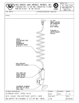
PRESSURIZED ALUMINUM PARTS HAZARD
Do not use 1,1,1-trichloroethane, methylene chloride, other halogenated hydrocar-
bon solvents or fluids containing such solvents in pressurized aluminum equipment.
Such use can cause serious chemical reaction and equipment rupture, and result in
death, serious injury, and property damage.
WARNING

Warnings
311075U 7
EQUIPMENT MISUSE HAZARD
Misuse can cause death or serious injury.
• This equipment is for professional use only.
• Do not leave the work area while equipment is energized or under pressure.
Turn off all equipment and follow the Pressure Relief Procedure in this manual
when equipment is not in use.
• Do not exceed the maximum working pressure or temperature rating of the low-
est rated system component. See Technical Data in all equipment manuals.
• Use fluids and solvents that are compatible with equipment wetted parts. See
Technical Data in all equipment manuals. Read fluid and solvent manufac-
turer’s warnings. For complete information about your material, request MSDS
from distributor or retailer.
• Check equipment daily. Repair or replace worn or damaged parts immediately
with genuine Graco replacement parts only.
• Do not alter or modify equipment.
• Use equipment only for its intended purpose. Call your Graco distributor for infor-
mation.
• Route hoses and cables away from traffic areas, sharp edges, moving parts, and
hot surfaces.
• Do not kink or over bend hoses or use hoses to pull equipment.
• Keep children and animals away from work area.
• Do not operate the unit when fatigued or under the influence of drugs or alcohol.
• Comply with all applicable safety regulations.
MOVING PARTS HAZARD
Moving parts can pinch or amputate fingers and other body parts.
• Keep clear of moving parts.
• Do not operate equipment with protective guards or covers removed.
• Pressurized equipment can start without warning. Before checking, moving, or
servicing equipment, follow the Pressure Relief Procedure in this manual. Dis-
connect power or air supply.
BURN HAZARD
Equipment surfaces and fluid that’s heated can become very hot during operation.
To avoid severe burns, do not touch hot fluid or equipment. Wait until equip-
ment/fluid has cooled completely.
WARNING

Overview
8 311075U
Overview
The Reactor E-10 is a portable, electric-pow-
ered, 1:1 mix ratio proportioner, for use with a
wide variety of coatings, foams, sealants, and
adhesives. Materials must be self-leveling and
pourable, and may be applied with impinge-
ment mix spray guns, disposable mixer guns,
or flush-type mix manifolds.
Reactor E-10 is gravity-fed from 7 gal. (26.5
liter) supply tanks mounted on the unit. The
tanks are translucent to allow monitoring of
fluid level.
Severe duty, positive displacement reciprocat-
ing piston pumps meter fluid flow to the gun for
mixing and applying. When set to recirculation
mode, Reactor E-10 will circulate fluids back to
the supply tanks.
Heated models include separate thermostati-
cally controlled heaters for each fluid, and an
insulated hose bundle with circulation return
hoses. This allows the hoses and gun to be
preheated to the desired temperature before
spraying. Digital displays show the tempera-
tures of the two fluids.
An electronic processor controls the motor,
monitors fluid pressures, and alerts the opera-
tor if errors occur. See STATUS Indicator,
page 13, for further information.
Reactor E-10 has two recirculation speeds,
slow and fast, and an adjustable pressure out-
put.
Slow Recirculation
• Slow circulation results in a higher tem-
perature transfer in the heater, so hoses
and gun heat up quicker.
• Good for touchup or low flow spraying, up
to moderate temperature.
• Not used to circulate full tanks up to tem-
perature.
• Use with 245 fa blowing agent foams, to
minimize heat returned to tank and reduce
frothing.
Fast Recirculation
• Use to support higher flow rates or higher
temperatures by preheating the tanks.
• Agitates fluid within tanks, to avoid heating
only the fluid at the top of the tank.
• Use for flushing.
Pressure Adjust
Automatically maintains selected pressure out-
put for dispensing or spraying.

Isocyanate Hazard
311075U 9
Isocyanate Hazard
Foam Self-ignition
Moisture Sensitivity of
Isocyanates
Isocyanates (ISO) are catalysts used in two
component foam and polyurea coatings. ISO
will react with moisture (such as humidity) to
form small, hard, abrasive crystals, which
become suspended in the fluid. Eventually a
film will form on the surface and the ISO will
begin to gel, increasing in viscosity. If used,
this partially cured ISO will reduce perfor-
mance and the life of all wetted parts.
To prevent exposing ISO to moisture:
• Always use a sealed container with a des-
iccant dryer in the vent, or a nitrogen atmo-
sphere. Never store ISO in an open
container.
• Keep the felt washers in the pump
wet-cups saturated with Graco ISO pump
oil, Part No. 217374. The lubricant creates
a barrier between the ISO and the atmo-
sphere.
• Use moisture-proof hoses specifically
designed for ISO, such as those supplied
with your system (see page 63).
• Never use reclaimed solvents, which may
contain moisture. Always keep solvent con-
tainers closed when not in use.
• Never use solvent on one side if it has
been contaminated from the other side.
• Always park pumps when you shutdown,
see page 27.
• Always lubricate threaded parts with Part
No. 217374 ISO pump oil or grease when
reassembling.
Spraying materials containing isocyanates
creates potentially harmful mists, vapors, and
atomized particulates.
Read material manufacturer’s warnings and
material MSDS to know specific hazards and
precautions related to isocyanates.
Prevent inhalation of isocyanate mists,
vapors, and atomized particulates by provid-
ing sufficient ventilation in the work area. If
sufficient ventilation is not available, a sup-
plied-air respirator is required for everyone in
the work area.
To prevent contact with isocyanates, appro-
priate personal protective equipment, includ-
ing chemically impermeable gloves, boots,
aprons, and goggles, is also required for
everyone in the work area.
Some materials may become self-igniting if
applied too thickly. Read material manufac-
turer’s warnings and material MSDS.
The amount of film formation and rate of
crystallization varies depending on the
blend of ISO, the humidity, and the tem-
perature.

Keep Components A and B Separate
10 311075U
Keep Components A
and B Separate
Changing Materials
• When changing materials, flush the equip-
ment multiple times to ensure it is thor-
oughly clean.
• Always clean the fluid inlet strainers after
flushing, see page 28.
• Check with your material manufacturer for
chemical compatibility.
• Most materials use ISO on the A side, but
some use ISO on the B side.
• Epoxies often have amines on the B (hard-
ener) side. Polyureas often have amines on
the B (resin) side.
NOTICE
To prevent cross-contamination of the equip-
ment’s wetted parts, never interchange com-
ponent A (isocyanate) and component B
(resin) parts.

Component Identification
311075U 11
Component Identification
Key for FIG. 1
A Supply Tank A
B Supply Tank B
C Pump A
D Pump B
E Heater A
F Heater B
G Fluid Pressure Gauges
H Recirc/Spray and Overpressure Relief Valves
J Control Panel; see F
IG. 3, page 13
K Electric Motor and Drive Housings
L Insulated Hose Bundle
(includes circulation return hoses)
M Fusion Air Purge Spray Gun
N Desiccant Dryer (mounts on supply tank A)
P Recirculation Tubes
Q Air Line Inlet (quick-disconnect fitting)
R Outlet Hose Connections
S Return Hose Connections
T Fluid Temperature Sensors
U Hose Rack and Control Shield
V Fluid Inlet Ball Valves (1 on each side)
W Fluid Inlet Strainers (1 on each side)
X Power Cord
Y Air Filter/Moisture Separator
F
IG
. 1: Component Identification, Heated Packages (Part No. AP9572 Shown)
WLD
A
N
B
C
D
E
F
G
H
J
K
L
M
P
P
R
S
T
T
U
V
W
X
Q
Y

Component Identification
12 311075U
Key for F
IG
. 2
A Supply Tank A
B Supply Tank B
C Pump A
D Pump B
G Fluid Pressure Gauges
H Recirc/Spray and Overpressure Relief Valves
J Control Panel; see F
IG. 3, page 13
K Electric Motor and Drive Housings
L Hose Bundle
M MD2 Cold Spray Gun (with disposable static
mixer) or 2K Manual Gun
N Desiccant Dryer (mounts on supply tank A)
P Recirculation Tubes
Q Air Line Inlet (quick-disconnect fitting)
R Outlet Hose Connections
U Hose Rack and Control Shield
V Fluid Inlet Ball Valves (1 on each side)
W Fluid Inlet Strainers (1 on each side)
X Power Cord
Z Air Filter/Moisture Separator
F
IG
. 2: Component Identification, Nonheated Packages (Part No. 249808 Shown)
WLD
A
N
B
C
D
G
H
J
K
L
M
P
P
R
U
V
W
X
Q
Z

Controls and Indicators
311075U 13
Controls and Indicators
Motor/Pump Control
Function Knob
Use knob (CF) to select desired function.
STATUS Indicator
• Indicator (ST) steady on: Motor Power
switch is turned on and control board is
working.
• Indicator (ST) blinking: If error occurs, STA-
TUS indicator will blink 1 to 7 times to indi-
cate status code, pause, then repeat. See
T
ABLE
1 for a brief description of status
codes. For more detailed information and
corrective action, see page 31.
F
IG
. 3. Controls and Indicators (heated unit shown)
MP
CF
ST
HP
TD TD
TI7016a
Icon Setting Function
Stop/Park Stops motor and auto-
matically parks pumps.
Slow
Recirc
Slow recirculation
speed.
Fast Recirc Fast recirculation
speed.
Pressure
Adjust
Adjusts fluid pressure
to gun in spray mode.
Table 1
: Status Codes
(see also the label on back of the control
enclosure)
Code
No. Code Name
1 Pressure imbalance between A and B
sides
2 Unable to maintain pressure setpoint
3 Pressure transducer A failure
4 Pressure transducer B failure
5 Excessive current draw
6 High motor temperature
7 No cycle counter switch input
The default is to shut down if a status
code indication occurs. Codes 1 and 2
may be set to disable automatic shut-
down if desired; see page 32. The other
codes are not settable.

Controls and Indicators
14 311075U
Motor Power Switch/Circuit
Breaker
Switch (MP) turns power on to control board
and function knob. The switch includes a 20 A
circuit breaker.
Heater Power Switch/Circuit
Breaker
See F
IG
. 3. Switch (HP) turns power on to
heater thermostats. The switch includes a 20 A
circuit breaker. Present on heated units only.
Heater Temperature
Controls
See F
IG
. 4. Control knobs (HC) set tempera-
ture of component A and B heaters. Indicator
lights (HL) turn on when thermostats are heat-
ing, and off when heater reaches setpoint.
Present on heated units only.
Fluid Temperature Sensors
and Displays
See F
IG
. 3. Fluid temperature sensors (T)
monitor actual temperature of component A
and B fluid going to spray gun. Temperatures
are then displayed (TD). Present on heated
units only.
Unit is shipped set to °F. To change to °C, see
page 43.
F
IG
. 4. Heater Temperature Controls
HC
HC
HL
HL
TI6984b
E
F
T
T

Setup
311075U 15
Setup
Connect Reactor E-10 to the correct power
source for your model. See T
ABLE
2. Models
with two power cords must be connected to
two separate, dedicated circuits. See F
IG
. 5.
Some models include cord adapters (55, 56)
for use outside North America. Connect the
appropriate adapter to the unit’s power cord
before connecting to your power source.
The equipment must be grounded. Grounding
reduces the risk of static and electric shock by
providing an escape wire for the electrical cur-
rent due to static build up or in the event of a
short circuit.
1.
Locate Reactor E-10
a.
Locate Reactor E-10 on a level
surface.
b.
Do not expose Reactor E-10 to
rain.
2.
Electrical requirements
Improper wiring may cause electric shock or
other serious injury if work is not performed
properly. Have a qualified electrician perform
any electrical work. Be sure your installation
complies with all National, State and Local
safety and fire codes.
3.
Ground system
a.
Reactor E-10: grounded through
power cord.
b.
Generator (if used): follow your
local code. Start and stop gener-
ator with power cord(s) discon-
nected.
c.
Spray gun: grounded through the
supplied fluid hoses, connected
to a properly grounded Reactor
E-10. Do not operate without at
least one grounded fluid hose.
d.
Object being sprayed: follow your
local code.
e.
Solvent pails used when flushing:
follow your local code. Use only
metal pails, which are conduc-
tive, placed on a grounded sur-
face. Do not place pail on a
nonconductive surface, such as
paper, plastic, or cardboard,
which interrupts grounding conti-
nuity.
f.
To maintain grounding continuity
when flushing or relieving pres-
sure, hold a metal part of spray
gun firmly to the side of a
grounded metal pail, then trigger
gun.

Setup
16 311075U
Table 2: Electrical Requirements
Model Required Power Source Power Cord Connector
120 V, 1 phase, 50/60 Hz, two
15 ft (4.5 m) power cords,
Heated
Two separate, dedicated cir-
cuits rated at minimum of 15
A each
240 V, 1 phase, 50/60 Hz, two
15 ft (4.5 m) power cords,
Heated
Two separate, dedicated cir-
cuits rated at minimum of 10
A each
240 V, 1 phase, 50/60 Hz, one
15 ft (4.5 m) power cord,
Heated
Single dedicated circuit rated
at minimum of 16 A
120 V, 1 phase, 50/60 Hz, one
15 ft (4.5 m) power cord, Non-
heated
Single dedicated circuit rated
at minimum of 15 A
240 V, 1 phase, 50/60 Hz, one
15 ft (4.5 m) power cord, Non-
heated
Single dedicated circuit rated
at minimum of 8 A
Two NEMA 5-15T
Two IEC 320, with
two local adapters:
Euro CEE74 Adapter
Australia/China Adapter
One NEMA 6-20P
One NEMA 5-15T
One NEMA 6-20P
Table 3: Extension Cord Requirements
Model
Required Wire Size
Up to 50 ft (15 m) Up to 100 ft (30 m)
Nonheated and two cord heated
models
AWG 14 AWG 12
Single cord heated model AWG 12 AWG 10
Cords must be 3-conductor grounded, rated for your
environment.

Setup
311075U 17
F
IG
. 5. Use Two Separate Circuits for Two Cord Models
1
Ensure no other high amp loads are connected
while running Reactor E-10.
To verify separate circuits, plug in Reactor E-10
or a worklight and cycle breakers on and off.
1
2
To avoid electric shock, always unplug both cords
before servicing Reactor E-10.
1
Heater Power
Motor Power
TI7061a
2
4.
Connect fluid hoses
Connect fluid supply hoses to outlet
hose connections (R, F
IG
. 6). Red hoses
for component A (ISO), blue for compo-
nent B (RES). Fittings are sized to pre-
vent connection errors. Connect other
end of hoses to A and B inputs of gun.
Heated units only: connect recirculation
hoses from gun recirculation ports to
connections (S).
5.
Connect gun air hose
For air operated guns only: Connect gun
air hose to the gun air input and to the
air filter outlet (Z). If you are using more
than one hose bundle, join the air hoses
with the nipple (305) provided with the
hose bundle.
On heated units with Fusion guns, con-
nect the supplied ball valve and
quick-disconnect coupler to the gun air
hose, then connect the coupler to the
gun air fitting.
6.
Connect main air supply
Connect the main air supply to the quick
disconnect fitting (Q) on the unit. Air
supply hose must be at least 5/16 in. (8
mm) ID up to 50 ft (15 m) or 3/8 in. (10
mm) ID up to 100 ft (30 m).
Air Filter/Moisture Separator (Z) is
equipped with an automatic moisture
drain.
7.
Flush before first use
The Reactor E-10 is tested with a plasti-
cizer oil at the factory. Flush out the oil
with a compatible solvent before spray-
ing. See page 29.

Setup
18 311075U
F
IG
. 6. Hose Connections
WLD
WLD
Heated Units
Nonheated Units
R
S
R
Q
Z
Z
Q
AIR
AIR
B (RES)
A (ISO)
A (ISO)
B (RES)

Setup
311075U 19
8.
Fill wet-cups
Keep the felt washers in the pump
wet-cups saturated with Graco ISO
pump oil, Part No. 217374. The lubri-
cant creates a barrier between the ISO
and the atmosphere.
Fill wet-cups through slots
in plate, or loosen screws
and swing plate aside.
TI6985a
Pump rod and connecting rod move during
operation. Moving parts can cause serious
injury such as pinching or amputation. Keep
hands and fingers away from wet-cup during
operation. Shut off Motor Power
before filling wet-cup.
9.
Fill fluid tanks
NOTICE
To prevent cross-contamination of fluids and
equipment parts, never interchange compo-
nent A (isocyanate) and component B (resin)
parts or containers.
Have at least two 5 gal. (19 liter) pails to
transfer fluid from drums to supply tanks.
Label one pail “A” and the other “B”, using
the red and blue labels provided. Always
doublecheck which material you have before
pouring it in the supply tanks. Pouring is eas-
ier if pails are not filled to the top.
Open only one supply tank at a time, to avoid
splashing material from one tank into the
other when filling.
Using a drill and mixing blade, mix filled or
separated materials in the pail before add-
ing to the tanks. Material left in the tanks
overnight may need to be remixed in the
tanks.

Setup
20 311075U
a.
Lift hose rack. Remove tank A
cover and pour ISO into tank A
(red side, with desiccant filter in
cover). Replace cover .
Desiccant filter is blue when fresh, and
turns pink when saturated. Be sure
shipping plugs are removed from open-
ings on desiccant filter.
b.
Remove tank B cover and pour
resin into tank B (blue side).
Replace cover .
.
Add thin coating of grease lubricant to tank o-ring if lid is difficult
to assemble to tank.
1
TI7017a
1
TI7018a
1
10.
Purge air and flush fluid from
lines
a.
Remove both recirculation tubes
(P) from the tanks and secure
each one in a dedicated waste
container.
b.
Set function knob to Stop/Park
.
c.
Plug in power cord(s). See T
ABLE
2, page 16.
d.
Open both pump fluid inlet valves
(V, shown in open position).
TI7022a
P
V
TI7019a
/