Hitachi CP-DX250 guide User manual
- Category
- Data projectors
- Type
- User manual
This manual is also suitable for

SPECIFICATIONS AND PARTS ARE SUBJECT TO CHANGE FOR IMPROVEMENT.
Multimedia DLP Projector
December 2012
YK
No.0682E
CP-DX250/CP-DX300
(DL1-X25/DL1-X30)
SERVICE MANUAL
Be sure to read this manual before servicing. To assure safety from fire, electric shock, injury, harmful
radiation and materials, various measures are provided in this Hitachi Multimedia DLP Projector.
Be sure to read cautionary items described in the manual to maintain safety before servicing.
Caution
1. When replace the lamp, to avoid burns to your fingers. The lamp becomes too hot.
2. Never touch the lamp bulb with a finger or anything else. Never drop it or give it a shock. They may
cause bursting of the bulb.
3. This projector is provided with a high voltage circuit for the lamp. Do not touch the electric parts of
power unit (circuit) and power unit (ballast), after turn on the projector.
4. Do not touch the exhaust fan, during operation.
5. Use the cables which are included with the projector or speci fied.
Service Warning
Warning
The technical information and parts shown in this
manual are not to be used for: the development,
design, production, storage or use of nuclear, chemical,
biological or missile weapons or other weapons of
mass destruction; or military purposes; or purposes that
endanger global safety and peace. Moreover, do not
sell, give, or export these items, or grant permission for
use to parties with such objectives. Forward all inquiries
to Hitachi Consumer Electronics Co., Ltd.
1. Features ------------------------------------------------------ 2
2. Specifications ----------------------------------------------- 3
3. Names of each part ----------------------------------------10
4. Adjustment ---------------------------------------------------13
5. Troubleshooting ------------------------------------------ 25
6. Service points --------------------------------------------- 35
7. Wiring diagram -------------------------------------------- 40
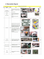
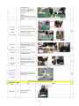
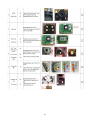
8. Disassembly diagram ----------------------------------- 55
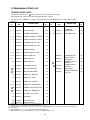
9. Replacement parts list ---------------------------------- 58
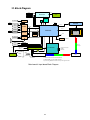
10. Block diagram --------------------------------------------- 59
11. - 60
RS-232------------------
-----------------------------------
Contents
6. The pictures and illustrations in this manual are for illustrative purposes.
They may differ slightly from the projector you work on.

1
Content Index
1. Features ................................................................................................................... 2
2. Specifications .......................................................................................................... 3
2.1 Specification Overview ..................................................................................... 3
2.2 Electrical Specification...................................................................................... 4
3. Names of Each Part ............................................................................................... 10
3.1 Projector Exterior View ................................................................................... 10
3.2 Control Panel ................................................................................................... 11
3.3 Remote Control .............................................................................................. 12
4. Adjustment ............................................................................................................. 13
4.1 Repair Flow .................................................................................................... 14
4.2 Basic Operating For Switching Modes ........................................................... 15
4.3 Service Tool .................................................................................................... 17
4.4 Adjustment and Alignment .............................................................................. 22
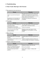
5. Troubleshooting .................................................................................................... 25
5.1 Basic Trouble Shooting for End Customer ...................................................... 25
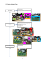
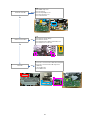
5.2 System Analysis Flow ..................................................................................... 26
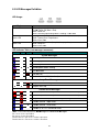
5.3 LED Messages Definition ............................................................................... 28
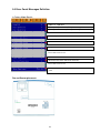
5.4 Error Count Messages Definition .................................................................... 29
5.5 Power Supply Trouble Shooting Guide ........................................................... 30
5.6 Optical Trouble Shooting Guide ...................................................................... 33
6. Service Points ........................................................................................................ 35
6.1 Maintenance ................................................................................................... 35
6.2 Replacing The Lamp ...................................................................................... 36
6.3 Resetting the Lamp Timer .............................................................................. 38
6.4 Screw / Torque List ......................................................................................... 39
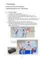
7. Wiring Diagram ...................................................................................................... 40
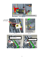
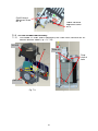
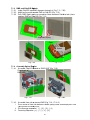
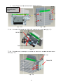
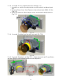
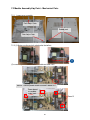
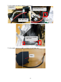
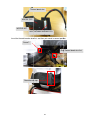
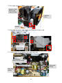
7.1 Module Assembly Key Point – Optical Engine ................................................ 40
7.2 Module Assembly Key Point – Mechanical Parts ............................................ 46
8. Disassembly Diagram ........................................................................................... 55
9. Replacement Parts List ......................................................................................... 58
10. Block Diagram ..................................................................................................... 59
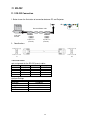
11. RS-232 ................................................................................................................... 60
11.1 RS-232 Connection ...................................................................................... 60
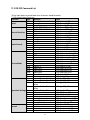
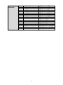
11.2 RS-232 Command List ................................................................................. 61
Appendix – Abbreviations & Acronyms................................................................... 63
Update History
Revision
Chapter Changes Date
Rev. 001
Initial version 2012/12/07

2
1. Features
The projector integrates high-performance optical engine projection and a user-friendly
design to deliver high reliability and ease of use.
The projector offers the following features.
• Presentation timer for better control of time during presentations
• Supports 3D display
• Color Management allowing color adjustments to your liking
• Less than 0.5W power consumption when standby mode is saving
• Wall Color correction allowing projection on surfaces of several predefined colors
• Quick auto search speeding up the signal detecting process
• Multiple sets of preset modes providing choices for different projection purposes
• One-key auto-adjustment to display the best picture quality
• Digital keystone correction to correct distorted images
• Adjustable color management control for data/video display
• High brightness projection lamp
• Ability to display 1.07 billion colors
• Multi-language On-Screen Display (OSD) menus
• Switchable normal and economic modes to reduce the power consumption
• Component HDTV compatibility (YPbPr)
• The apparent brightness of the projected image will vary depending on the ambient
lighting conditions, selected input signal contrast/brightness settings, and is
directly proportional to projection distance.
• The lamp brightness will decline over time and may vary within the lamp
manufacturer’s specifications. This is normal and expected behavior.

3
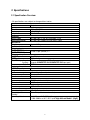
2. Specifications
2.1 Specification Overview
• All specifications are subject to change without notice.
General
Product name Projector
Optical
Resolution
1024 x 768 XGA
Display system
1-CHIP DMD
Lamp
196 W UHP
Electrical
Power supply
AC 100-120V: 2.9 A, AC 220-240V: 1.4 A
Power consumption
AC 100-120V: 250W, AC 220-240V: 235W
Mechanical
Weight
Approx. 2.2 kg
Input terminal
Computer input
COMPUTER IN1
port
D-Sub 15-pin (female) x 2
COMPUTER IN2
port
Video signal input
S
-
VIDEO
port
Mini DIN 4-pin x 1
VIDEO
port
RCA x 1
SD/HDTV signal input
Analog –
D-Sub <–> Component RCA x 3
(through COMPUTER IN1/COMPUTER IN2 input port)
Digital –
HDMI
x 1
Audio signal input
AUDIO IN
port
Stereo mini x 1
Output
terminal
MONITOR OUT
port
D-Sub 15-pin (female) x 1
AUDIO OUT
port
Stereo mini x 1
Speaker
2 watt x 1
Control terminal
CONTROL
port
RS-232 serial control 9 pin x 1
IR receiver
x 1 (Front)
Service terminal
SERVICE
port
USB mini B x 1
Environmental
Requirements
Operating temperature
0°C–40°C at sea level
Operating relative
humidity
10%–90% (without condensation)
Operating altitude
• 0–1499 m at 0°C–35°C (with
High Altitude Mode 2 (Normal)
)
• 1500–3000 m at 0°C–30°C (with High Altitude Mode 1 (High))

4
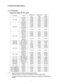
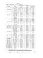
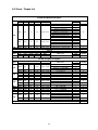
2.2 Electrical Specification
2.2.1 Timing Table

5

6

7
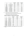
2.2.2 Characteristics of inputs/outputs
Signal Parameter Min Type Max
RDATA
GDATA
BDATA
Impedance 75 Ohm
Amplitude 0.7 Volts peak-to-peak
Black pedestal 0 Volts
Pixel Clock 165 M Hz
GDATA_SOG Impedance 75 Ohm
Amplitude 1 Volts peak-to-peak
Video amplitude 0.7 Volts peak-to-peak
Sync amplitude 0.3 Volts peak-to-peak
Black pedestal 0 Volts
Pixel Clock 165 M Hz
HDATA Impedance 1 K ohm
Amplitude, low level 0 0.8 Volt
Amplitude, high level 2.5 5 Volt
Frequency 31 99 K Hz
VDATA Impedance 1 K ohm
Amplitude, low level 0 0.8 volt
Amplitude, high level 2.5 5 Volt
Frequency 48 120 Hz
SDADATA Amplitude, low level 0 0.8 volt
Amplitude, high level 3 5 Volt
SCLDATA Amplitude, low level 0 0.8 volt
Amplitude, high level 3 5 Volt
RXD Amplitude -25 25 Volt
TXD Amplitude -13.2
13.2 Volt
CVBS
Luminance
Amplitude, total (video+
sync)
1 Volts peak to peak
Amplitude, video 0.7 Volts peak to peak
Amplitude, sync 0.3 Volts peak to peak
Impedance 75 ohm
CVBS Chroma
Amplitude 700 m Volts peak to peak
Impedance 75 ohm
Audio Impedance (audio in) 10 Kohm
Amplitude (audio in) 0 500 mVolt rms
Bandwidth 300Hz
16kHz
S/N Ratio 40 dB
Total Harmonic Distortion 10 %

8
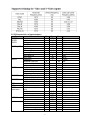
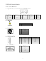
2.2.3 Electrical Interface Character
2.2.3.1 Interface Definition:
::
:
15 pin definition of the mini D-sub female for DDC2B protocol
Pin
Definition Pin
Definition Pin
Definition Pin
Definition
Pin
Definition
1 Red (Pr) 2 Green (Y) 3 Blue (Pb) 4 NC 5 NC
6 Red return
7 Green return
8 Blue return
9 DDCP 5V
10
GND
11
GND 12
SDA 13
H-sync 14
V-sync 15
SCL
Video Input
S-Video input
Pin
Definition
1 GND
2 GND
3 Luminance
4 Chroma
RS232 Control Port
Mini USB TYPE B
Pin
Definition
1 Composite video input
Pin
Definition Pin
Definition
1 NC 2 RX
3 TX 4 NC
5 GND 6 NC
7 RTSZ 8 CTSZ
9 NC
Pin
Definition
1 Vbus
2 D-
3 D+
4 ID
5 GND

9
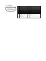
HDMI Input
Pin
Pin definition Pin
Pin definition
1 TMDS Data2+ 11
TMDS Clock Shield
2 TMDS Data2 Shield
12
TMDS Clock–
3 TMDS Data2– 13
CEC
4 TMDS Data1+ 14
Reserved (N.C. on device)
5 TMDS Data1 Shield
15
SCL
6 TMDS Data1– 16
SDA
7 TMDS Data0+ 17
DDC/CEC Ground
8 TMDS Data0 Shield
18
+5V Power
9 TMDS Data0– 19
Hot Plug Detect
10
TMDS Clock+

10
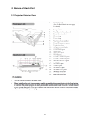
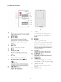
3. Names of Each Part
3.1 Projector Exterior View
(See Control Panel on next page
for detail)

11
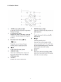
3.2 Control Panel

12
3.3 Remote Control

13
4. Adjustment
4.1 Repair Flow
4.2 Basic Operating For Switching Modes
4.3 Service Tool
4.4 Adjustment and Alignment
4.4.1 Color Wheel Delay Alignment
4.4.2 PC Alignment Procedure
4.4.3 Overfill (Blue-Edge) adjustment

14
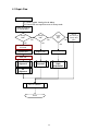
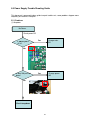
4.1 Repair Flow
Check connectivity
or change parts
(1) Follow Trouble shooting flow to debug
(2) Check LED message/Error count in factory mode
Function Abnormal
Change
M/B?
Yes
Replace M/B
No
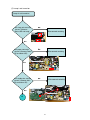
CW delay
Alignment
PC
Alignment
Change
CW?
CW delay
Alignment
No
Yes
Replace CW
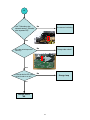
Burn-In (10mins)
Finish
Check
connectivity or
change other
parts
Change
Light
Pipe?
Overfill (Blue
Edge)
Adjustmen
t
Yes
No
Use
Service
Tool
to
Write
S/N
Use
Service
Tool
to
R
e
ad
S/N
Replace Light Pipe

15
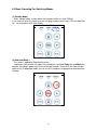
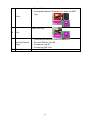
4.2 Basic Operating For Switching Modes
(1) Standby Mode:
::
:
When standby mode, system power consumption will be less than 0.5Watt.
If user wants to enter this mode, user can just plug in power cord. Power LED will show Red
for 1 sec then power LED show Purple.
Standby Mode
(2) Download Mode:
::
:
This mode is applied for Download firmware.
If operators want to enter this mode, they should press and hold Power key and Mode key
together, then plug in power cord. Release the two keypads. Power LED will show red light
continuously. In download mode, you can use DLP composer lite program to download new
firmware.
Download Mode

16
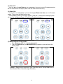
(3) Power On:
::
:
User can press Keypad Power to turn on projector. User can also use IR remote control to
do this action. When turning on, power LED will show blue continuously.
(4) Power Off:
::
:
If user wants turn off projector, user can click keypad Power two times, or use IR remote
control. Then system will cool itself via fans.
During cooling, Power LED will flash Purple (1 time per 1 second). After cooling, System
will return to standby and Power LED will show Purple continuously.
Power On
Power Off
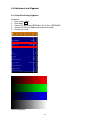
(5) Method to Enter Factory mode:
::
:
1. Press Menu key, OSD will show the menu image.
2. Then click SOURCE key and MODE/ENTER key together, system will enter the
Factory mode.
<Notice: > Repair center could check Error Count Message in Factory Mode Block 4.
(See Section5--Error Count Messages Definition)

17
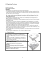
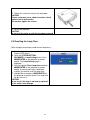
4.3 Service Tool
When to use service tool:
– Before FW re-downloading or replacing a new Main board, need to read data from
Main board by service tool.
– After FW downloading or a replacing a new Main board, need to write data into Main
Board by service tool.
Service Tool Required:
::
:
– PC
– RS-232 cross cable (Cable spec refer to Section 12. RS-232)
Service Tool install procedure (for the first use)
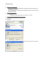
(1) Installation:
1. Double click the Setup file for installing program.
2. Click “OK.”
3. Change an installation directory or agree default directory and then click the icon button.

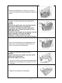
18
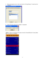
4. Enter a new group name or select one from the “Existing Groups” list and then click
“Continue.”
5. Click “OK” and a successful installation is completed.
<Notice: > Before using Service tool, please check the Control Method in Factory Mode
Block 1 must be set as “RS232.”

19
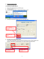
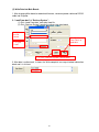
How to Use Service Tool
(1) Read Data From Main Board:
1. Connect PC with projector by a RS232 cable.
2. Turn on projector.
3. From Windows Start Menu -> Select “Service Tool” -> “Tool.”
4. Change to connected COM port and Click “Port Open” icon.
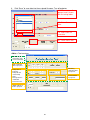
5. Read data from original Main board:
Click “Read system Data”, and it will read the Adjustment data & Serial Number from
projector, and show the “Read complete” message in below information block.
5-1. Click this icon to
read all data
5-2. Show “Read
Complete!”
4-1. Change to
connected COM Port
number
4-2. Click “Port
Open”
Page is loading ...
Page is loading ...
Page is loading ...
Page is loading ...
Page is loading ...
Page is loading ...
Page is loading ...
Page is loading ...
Page is loading ...
Page is loading ...
Page is loading ...
Page is loading ...
Page is loading ...
Page is loading ...
Page is loading ...
Page is loading ...
Page is loading ...
Page is loading ...
Page is loading ...
Page is loading ...
Page is loading ...
Page is loading ...
Page is loading ...
Page is loading ...
Page is loading ...
Page is loading ...
Page is loading ...
Page is loading ...
Page is loading ...
Page is loading ...
Page is loading ...
Page is loading ...
Page is loading ...
Page is loading ...
Page is loading ...
Page is loading ...
Page is loading ...
Page is loading ...
Page is loading ...
Page is loading ...
Page is loading ...
Page is loading ...
Page is loading ...
Page is loading ...
Page is loading ...
-
 1
1
-
 2
2
-
 3
3
-
 4
4
-
 5
5
-
 6
6
-
 7
7
-
 8
8
-
 9
9
-
 10
10
-
 11
11
-
 12
12
-
 13
13
-
 14
14
-
 15
15
-
 16
16
-
 17
17
-
 18
18
-
 19
19
-
 20
20
-
 21
21
-
 22
22
-
 23
23
-
 24
24
-
 25
25
-
 26
26
-
 27
27
-
 28
28
-
 29
29
-
 30
30
-
 31
31
-
 32
32
-
 33
33
-
 34
34
-
 35
35
-
 36
36
-
 37
37
-
 38
38
-
 39
39
-
 40
40
-
 41
41
-
 42
42
-
 43
43
-
 44
44
-
 45
45
-
 46
46
-
 47
47
-
 48
48
-
 49
49
-
 50
50
-
 51
51
-
 52
52
-
 53
53
-
 54
54
-
 55
55
-
 56
56
-
 57
57
-
 58
58
-
 59
59
-
 60
60
-
 61
61
-
 62
62
-
 63
63
-
 64
64
-
 65
65


Hitachi CP-DX250 guide User manual
- Category
- Data projectors
- Type
- User manual
- This manual is also suitable for
Ask a question and I''ll find the answer in the document
Finding information in a document is now easier with AI
Related papers
Other documents
-
ViewSonic PS501X-S Operating instructions
-
ViewSonic PS750W-S Operating instructions
-
ViewSonic PA503S Operating instructions
-
BenQ MX662 User manual
-
West Elm Solid Oak Oval Coffee Table Assembly Instructions
-
Acer VZ.J9000.001 Datasheet
-
BenQ SP920 User manual
-
Cineversum ial-DLP User manual
-
Duracell DL1/3N User manual
-
Barco RLM R6+ Performer User manual