Gigabyte GA-945PL-S3 User manual
- Category
- Motherboards
- Type
- User manual

GA-945PL-S3
Intel
®
Core
TM
2 Extreme / Core
TM
2 Duo
Intel
®
Pentium
®
D / Pentium
®
4 LGA775 Processor Motherboard
User's Manual
Rev. 1001
12ME-945PLS3-1001R
* The WEEE marking on the product indicates this product must not be disposed of with user's other household waste
and must be handed over to a designated collection point for the recycling of waste electrical and electronic equipment!!
* The WEEE marking applies only in European Union's member states.

Motherboard
GA-945PL-S3
Jul. 07, 2006
Jul. 07, 2006
Motherboard
GA-945PL-S3

Copyright
© 2006 GIGA-BYTE TECHNOLOGY CO., LTD. All rights reserved.
The trademarks mentioned in the manual are legally registered to their respective companies.
Notice
The written content provided with this product is the property of Gigabyte.
No part of this manual may be reproduced, copied, translated, or transmitted in any form or by any
means without Gigabyte's prior written permission. Specifications and features are subject to
change without prior notice.
Product Manual Classification
In order to assist in the use of this product, Gigabyte has categorized the user manual in the
following:
For quick installation, please refer to the "Hardware Installation Guide" included with the
product.
For detailed product information and specifications, please carefully read the
"Product User Manual".
For detailed information related to Gigabyte's unique features, please go to the
"Technology Guide" section on Gigabyte's website to read or download the information
you need.
For more product details, please visit Gigabyte's website at www.gigabyte.com.tw

- 4 -
Table of Contents
Item Checklist ................................................................................................................. 6
Optional Accessories ...................................................................................................... 6
GA-945PL-S3 Motherboard Layout ............................................................................... 7
Block Diagram ................................................................................................................ 8
Chapter 1 Hardware Installation .................................................................................... 9
1-1 Considerations Prior to Installation .................................................................... 9
1-2 Feature Summary .......................................................................................... 10
1-3 Installation of the CPU and CPU Cooler ....................................................... 12
1-3-1 Installation of the CPU ......................................................................................... 12
1-3-2 Installation of the CPU Cooler ............................................................................ 13
1-4 Installation of Memory .................................................................................... 14
1-5 Installation of Expansion Cards ...................................................................... 16
1-6 I/O Back Panel Introduction ........................................................................... 17
1-7 Connectors Introduction .................................................................................. 18
Chapter 2 BIOS Setup ................................................................................................ 29
The Main Menu (For example: BIOS Ver. : E6) ....................................................... 30
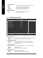
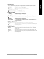
2-1 Standard CMOS Features ............................................................................. 32
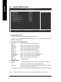
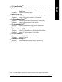
2-2 Advanced BIOS Features .............................................................................. 34
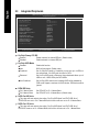
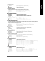
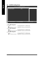
2-3 Integrated Peripherals ..................................................................................... 36
2-4 Power Management Setup ............................................................................. 38
2-5 PnP/PCI Configurations................................................................................. 40
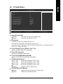
2-6 PC Health Status ........................................................................................... 41
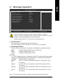
2-7 MB Intelligent Tweaker(M.I.T.) ....................................................................... 43
2-8 Load Fail-Safe Defaults ................................................................................... 46
2-9 Load Optimized Defaults ................................................................................. 46
2-10 Set Supervisor/User Password ..................................................................... 47
2-11 Save & Exit Setup ......................................................................................... 48
2-12 Exit Without Saving ....................................................................................... 48

- 5 -
Chapter 3 Install Drivers ............................................................................................. 49
3-1 Install Chipset Drivers .................................................................................... 49
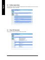
3-2 Software Applications ..................................................................................... 50
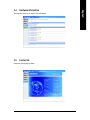
3-3 Driver CD Information .................................................................................... 50
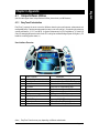
3-4 Hardware Information ..................................................................................... 51
3-5 Contact Us ..................................................................................................... 51
Chapter 4 Appendix ................................................................................................... 53
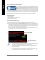
4-1 Unique Software Utilities ................................................................................ 53
4-1-1 EasyTune 5 Introduction ..................................................................................... 53
4-1-2 Xpress Recovery2 Introduction ......................................................................... 54
4-1-3 Flash BIOS Method Introduction ........................................................................ 56
4-1-4 2- / 4- / 6- / 8- Channel Audio Introduction ...................................................... 65
4-2 Troubleshooting ............................................................................................... 71

- 6 -
Item Checklist
IDE Cable x 1, FDD Cable x 1
SATA 3Gb/s Cable x 2
I/O Shield
* The items listed above are for reference only, and are subject to change without notice.
Optional Accessories
2 Ports USB2.0 Cable (Part Number: 12CR1-1UB030-51/R)
5.1/7.1 Surround Cable (Part Number: 12CF1-1AU004-01R )

- 7 -
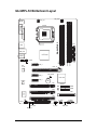
GA-945PL-S3 Motherboard Layout
KB_MS
COMA
LPT
CPU_FAN
ATX_12V
LGA775
IT8718
GA-945PL-S3
ATX
Intel
®
945PL
USB_LAN
USB
SPDIF_IO
FDD
PWR_LED
PCI3
F_USB2
F_PANEL
F_USB1
CODEC
HDA_SUR
CD_IN
SATAII0
IDE1
BIOS
SYS _FAN
Intel
®
ICH7
PCI2
PCIE_16
BAT
F_AUDIO
DDRII1
PCIE_3
CLR_CMOS
AUDIO
DDRII2
RTL
8111B
SATAII3
SATAII2
SATAII1
DDRII3
DDRII4
PCIE_1
PCIE_2
CI
PCI1

- 8 -
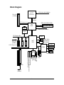
Block Diagram
LGA775
Processor
CPUCLK+/-(200/133MHz)
PCI Express x16
Host
Interface
Intel
®
945PL
MCHCLK(200/133MHz)
DDRII 400/533MHz DIMM
Dual Channel Memory
COM Port
Floppy
PS/2 KB/Mouse
4 SATA 3Gb/s
ATA33/66/100
IDE1 Channel
BIOS
8 USB
Ports
PCI CLK
(33MHz)
3 PCI
PCI Bus
LPT Port
PCIe CLK
(100MHz)
RJ45
RTL
8111B
Line-Out
MIC
CODEC
Line-In
SPDIF In
SPDIF Out
Center/Subwoofer Speaker Out
Side Speaker Out
Surround Speaker Out
PCI Express Bus
IT8718
Intel
®
ICH7
x1
3 PCI Express x1
PCIe CLK
(100MHz)
x1
x1
x1

Hardware Installation- 9 -
English
1-1 Considerations Prior to Installation
Preparing Your Computer
The motherboard contains numerous delicate electronic circuits and components which can
become damaged as a result of electrostatic discharge (ESD). Thus, prior to installation, please
follow the instructions below:
1. Please turn off the computer and unplug its power cord.
2. When handling the motherboard, avoid touching any metal leads or connectors.
3. It is best to wear an electrostatic discharge (ESD) cuff when handling electronic components
(CPU, RAM).
4. Prior to installing the electronic components, please have these items on top of an antistatic
pad or within a electrostatic shielding container.
5. Please verify that the power supply is switched off before unplugging the power supply connector
from the motherboard.
Installation Notices
1. Prior to installation, please do not remove the stickers on the motherboard. These stickers
are required for warranty validation.
2. Prior to the installation of the motherboard or any hardware, please first carefully read the
information in the provided manual.
3. Before using the product, please verify that all cables and power connectors are connected.
4. To prevent damage to the motherboard, please do not allow screws to come in contact with
the motherboard circuit or its components.
5. Please make sure there are no leftover screws or metal components placed on the motherboard
or within the computer casing.
6. Please do not place the computer system on an uneven surface.
7. Turning on the computer power during the installation process can lead to damage to system
components as well as physical harm to the user.
8. If you are uncertain about any installation steps or have a problem related to the use of the
product, please consult a certified computer technician.
Instances of Non-Warranty
1. Damage due to natural disaster, accident or human cause.
2. Damage as a result of violating the conditions recommended in the user manual.
3. Damage due to improper installation.
4. Damage due to use of uncertified components.
5. Damage due to use exceeding the permitted parameters.
6. Product determined to be an unofficial Gigabyte product.
Chapter 1Hardware Installation

GA-945PL-S3 Motherboard - 10 -
English
1-2 Feature Summary
CPU Supports LGA775 Intel
®
Core
TM
2 Extreme / Core
TM
2 Duo / Pentium
®
D /
Pentium
®
4
L2 cache varies with CPU
Front Side Bus Supports 800/533MHz FSB
Chipset Northbridge: Intel
®
945PL Express Chipset
Southbridge: Intel
®
ICH7
LAN Onboard RTL8111B chip (10/100/1000Mbit)
Audio Onboard Realtek ALC883 CODEC chip
Supports High Definition Audio
Supports 2 / 4 / 6 / 8 channel audio
(Note 1)
Supports SPDIF In/Out connection
Supports CD In connection
Storage Intel
®
ICH7
- 1 FDD connector, allowing connection of 1 FDD devices
- 1 IDE connector (IDE1) with UDMA 33/ATA 66/ATA 100 support,
allowing connection of 2 IDE devices
- 4 SATA 3Gb/s connectors (SATAII0, SATAII1, SATAII2, SATAII3),
allowing connection of 4 SATA 3Gb/s devices
O.S Support Microsoft Windows 2000/XP
Memory 4 DDRII DIMM memory slots (supports up to 2GB memory)
Supports dual channel DDRII 400/533
(Note 2)
DIMMs
Supports 1.8V DDRII DIMMs
Expanstion Slots 1 PCI Express x16 slot
3 PCI Express x1 slots
3 PCI slots
Internal Connectors 1 24-pin ATX power connector
1 4-pin ATX 12V power connector
1 floppy connector
1 IDE connector
4 SATA 3Gb/s connectors
1 CPU fan connector
1 system fan connector
1 front panel connector
1 front audio connector
1 CD In connector
1 power LED connector
2 USB 2.0/1.1 connectors for additional 4 USB 2.0/1.1 ports by cables
1 SPDIF In/Out connector
1 HDA_SUR connector

Hardware Installation- 11 -
English
Rear Panel I/O 1 PS/2 keyboard port
1 PS/2 mouse port
1 parallel port
1 serial port (COMA)
4 USB 2.0/1.1 port
1 RJ-45 ports
3 audio jacks (Line In / Line Out / MIC In)
I/O Control IT8718 chip
Hardware Monitor System voltage detection
CPU temperature detection
CPU / System fan speed detection
CPU warning temperature
CPU / System fan failure warning
Supports CPU Smart Fan function
BIOS 1 4Mbit flash ROM
Use of licensed AWARD BIOS
Additional Features Supports @BIOS
Supports Download Center
Supports Q-Flash
Supports EasyTune
(Note 3)
Supports Xpress Install
Supports Xpress Recovery2
Supports Xpress BIOS Rescue
Bundle Software Norton Internet Security (OEM version)
Form Factor ATX form factor; 30.5cm x 19.3cm
(Note 1) To set up an 8 channel audio configuration, you must use 5.1/7.1 Surround Cable (optional).
(Note 2) Some memory configurations will result in memory frequency being reduced from 533MHz
down to 400MHz. (Please refer to to Page 15 for more information.)
(Note 3) EasyTune functions may vary depending on different motherboards.

GA-945PL-S3 Motherboard - 12 -
English
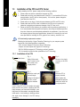
1-3 Installation of the CPU and CPU Cooler
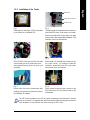
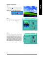
1-3-1 Installation of the CPU
Fig. 1
Gently lift the metal
lever located on the
CPU socket to the
upright position.
Metal Lever
Fig. 2
Remove the plastic
covering on the CPU
socket.
Fig. 3
Notice the small gold
colored triangle
located on the edge of
the CPU socket.
Align the indented
Fig. 4
Once the CPU is
properly inserted,
please replace the
load plate and push the
metal lever back into
its original position.
corner of the CPU with the triangle and gently
insert the CPU into position. (Grasping the CPU
firmly between your thumb and forefinger, care-
fully place it into the socket in a straight and down-
wards motion. Avoid twisting or bending motions
that might cause damage to the CPU during
installation.)
Before installing the CPU, please comply with the following conditions:
1. Please make sure that the motherboard supports the CPU.
2. Please take note of the one indented corner of the CPU. If you install the CPU in the
wrong direction, the CPU will not insert properly. If this occurs, please change the
insert direction of the CPU.
3. Please add an even layer of heat sink paste between the CPU and CPU cooler.
4. Please make sure the CPU cooler is installed on the CPU prior to system use,
otherwise overheating and permanent damage of the CPU may occur.
5. Please set the CPU host frequency in accordance with the processor specifications. It
is not recommended that the system bus frequency be set beyond hardware specifica-
tions since it does not meet the required standards for the peripherals. If you wish to set
the frequency beyond the proper specifications, please do so according to your hard-
ware specifications including the CPU, graphics card, memory, hard drive, etc.
HT functionality requirement content :
Enabling the functionality of Hyper-Threading Technology for your computer system
requires all of the following platform components:
- CPU: An Intel
®
Pentium 4 Processor with HT Technology
- Chipset: An Intel
®
Chipset that supports HT Technology
- BIOS: A BIOS that supports HT Technology and has it enabled
- OS: An operation system that has optimizations for HT Technology

Hardware Installation- 13 -
English
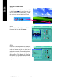
1-3-2 Installation of the Cooler
Male Push Pin
Female Push Pin
The top of Female Push Pin
The CPU cooler may adhere to the CPU as a result of hardening of the heat paste. To prevent
such an occurrence, it is suggested that either thermal tape rather than heat paste be used for
heat dissipation or using extreme care when removing the CPU cooler.
Fig. 6
Finally, please attach the power connector of the
CPU cooler to the CPU fan header located on the
motherboard.
Fig. 3
Place the CPU cooler atop the CPU and make
sure the push pins aim to the pin hole on the
motherboard.Pressing down the push pins
diagonally.
Fig. 4
Please make sure the Male and Female push pin
are joined closely. (for detailed installation
instructions, please refer to the CPU cooler instal-
lation section of the user manual)
Fig. 5
Please check the back of motherboard after
installing. If the push pin is inserted as the picture,
the installation is complete.
Fig.1
Please apply an even layer of CPU cooler paste
on the surface of the installed CPU.
Fig. 2
(Turning the push pin along the direction of arrow is to
remove the CPU cooler, on the contrary, is to install.)
Please note the direction of arrow sign on the male
push pin doesn't face inwards before installation. (This
instruction is only for Intel boxed fan)

GA-945PL-S3 Motherboard - 14 -
English
Before installing the memory modules, please comply with the following conditions:
1. Please make sure that the memory used is supported by the motherboard. It is
recommended that memory of similar capacity, specifications and brand be used.
2. Before installing or removing memory modules, please make sure that the computer power
is switched off to prevent hardware damage.
3. Memory modules have a foolproof insertion design. A memory module can be installed in
only one direction. If you are unable to insert the module, please switch the direction.
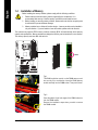
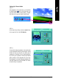
1-4 Installation of Memory
The motherboard supports DDRII memory modules, whereby BIOS will automatically detect memory
capacity and specifications. Memory modules are designed so that they can be inserted only in one direction.
The memory capacity used can differ with each slot.
Notch
DDRII
Fig.1
The DIMM socket has a notch, so the DIMM memory mod-
ule can only fit in one direction. Insert the DIMM memory
module vertically into the DIMM socket. Then push it down.
Fig.2
Close the plastic clip at both edges of the DIMM sockets to
lock the DIMM module.
Reverse the installation steps when you wish to remove
the DIMM module.

Hardware Installation- 15 -
English
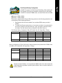
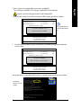
Dual Channel Memory Configuration
GA-945PL-S3 supports the Dual Channel Technology. After operating the
Dual Channel Technology, the bandwidth of Memory Bus will add double.
GA-945PL-S3 includes 4 DIMM sockets, and each Channel has two DIMM
sockets as following:
Channel 0 : DDRII1, DDRII2
Channel 1 : DDRII3, DDRII4
If you want to operate the Dual Channel Technology, please note the following explanations due
to the limitation of Intel chipset specifications.
1. Dual Channel mode will not be enabled if only one/three DDRII memory module is
installed.
2. To enable Dual Channel mode with two or four memory modules (it is recommended to
use memory modules of identical brand, size, chips, and speed), install the memory
according to the dual channel memory configuration table below (Figure 1).
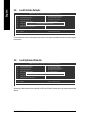
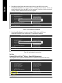
Memory configurations in Figure 2 will result in memory frequency being reduced from 533MHz down
to 400MHz. (DS: Double Side, SS: Single Side, X: Empty)
Figure 1
2 memory modules
4 memory modules
DDRII1 DDRII2 DDRII3 DDRII4
DS/SS X DS/SS X
DS/SS X X DS/SS
X DS/SS DS/SS X
X DS/SS X DS/SS
SS SS SS SS
Dual Channel Memory Configuration Table (DS: Double Side, SS: Single Side, X: Empty)
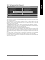
Figure 2
2 memory modules
3 memory modules
4 memory modules
DDRII1 DDRII2 DDRII3 DDRII4
SS SS X X
XXSSSS
SS SS DS/SS X
SS SS X DS/SS
DS/SS X SS SS
X DS/SS SS SS
SS SS SS SS
Because of chipset limitations, do not populate both DIMM sockets of the same channel with
double-sided memory modules to prevent system's failure to start or incorrect detection of
memory modules,

GA-945PL-S3 Motherboard - 16 -
English
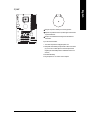
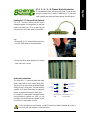
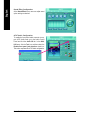
1-5 Installation of Expansion Cards
You can install your expansion card by following the steps outlined below:
1. Read the related expansion card's instruction document before install the expansion card into the
computer.
2. Remove your computer's chassis cover, screws and slot bracket from the computer.
3. Press the expansion card firmly into expansion slot in motherboard.
4. Be sure the metal contacts on the card are indeed seated in the slot.
5. Replace the screw to secure the slot bracket of the expansion card.
6. Replace your computer's chassis cover.
7. Power on the computer, if necessary, setup BIOS utility of expansion card from BIOS.
8. Install related driver from the operating system.
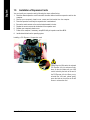
Installing a PCI Express x16 expansion card:
Please align the VGA card to the onboard
PCI Express x16 slot and press firmly
down on the slot. Make sure your VGA
card is locked by the latch at the end of
the PCI Express x16 slot. When you try
uninstall the VGA card, please gently
press the latch as the picture to the left
shows to release the card.

Hardware Installation- 17 -
English
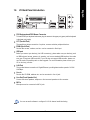
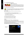
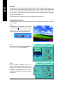
1-6 I/O Back Panel Introduction
PS/2 Keyboard and PS/2 Mouse Connector
To install a PS/2 port keyboard and mouse, plug the mouse to the upper port (green) and the keyboard
to the lower port (purple).
LPT (Parallel Port)
The parallel port allows connection of a printer, scanner and other peripheral devices.
COMA (Serial Port)
Devices like mouses, modems, and etc. can be connected to Serial port.
USB port
Before you connect your device(s) into USB connector(s), please make sure your device(s) such
as USB keyboard, mouse, scanner, zip, speaker...etc. have a standard USB interface. Also make
sure your OS supports USB controller. If your OS does not supportUSB controller, please con-
tact OS vendor for possible patch or driver upgrade. For more information please contact your
OS or device(s) vendors.
LAN Port
The provided Internet connection is Gigabit Ethernet, providing data transfer speeds of 10/100/
1000Mbps.
Line In
Devices like CD-ROM, walkman etc. can be connected to Line In jack.
Line Out (Front Speaker Out)
Connect the stereo speakers, earphone or front surround speakers to this connector.
MIC In
Microphone can be connected to MIC In jack.
You can use audio software to configure 2-/4-/6-/8- channel audio functioning.

GA-945PL-S3 Motherboard - 18 -
English
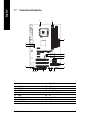
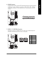
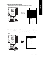
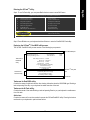
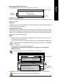
1-7 Connectors Introduction
1) ATX_12V
2) ATX (Power Connector)
3) CPU_FAN
4) SYS_FAN
5) IDE1
6) FDD
7) SATAII0 / 1 / 2 / 3
8) PWR_LED
9) F_AUDIO
10) F_PANEL
11) CD_IN
12) SPDIF_IO
13) HDA_SUR
14) F_USB1 / F_USB2
15) C I
16) CLR_CMOS
17) BAT
1
2
3
8
14
17
15
12
16
11
10
5
64
13
9
7

Hardware Installation- 19 -
English
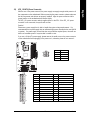
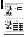
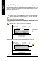
1/2) ATX_12V/ATX (Power Connector)
With the use of the power connector, the power supply can supply enough stable power to all
the components on the motherboard. Before connecting the power connector, please make sure
that all components and devices are properly installed. Align the power connector with its
proper location on the motherboard and connect tightly.
The ATX_12V power connector mainly supplies power to the CPU. If the ATX_12V power
connector is not connected, the system will not start.
Caution!
Please use a power supply that is able to handle the system voltage requirements. It is
recommended that a power supply that can withstand high power consumption be used (300W
or greater). If a power supply is used that does not provide the required power, the result can
lead to an unstable system or a system that is unable to start.
If you use a 24-pin ATX power supply, please remove the small cover on the power connector
on the motherboard before plugging in the power cord ; otherwise, please do not remove it.
Pin No. Definition
1 GND
2 GND
3 +12V
4 +12V
1
13
24
12
Pin No. Definition
13 3.3V
14 -12V
15 GND
16 PS_ON(soft On/Off)
17 GND
18 GND
19 GND
20 -5V
21 +5V
22 +5V
23 +5V (Only for 24-pin ATX)
24 GND(Only for 24-pin ATX)
Pin No. Definition
1 3.3V
2 3.3V
3 GND
4 +5V
5 GND
6 +5V
7 GND
8 Power Good
9 5V SB(stand by +5V)
10 +12V
11 +12V(Only for 24-pin ATX)
12 3.3V(Only for 24-pin ATX)
1
3
2
4

GA-945PL-S3 Motherboard - 20 -
English
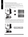
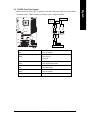
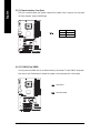
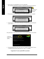
3/4) CPU_FAN / SYS_FAN (Cooler Fan Power Connector)
The cooler fan power connector supplies a +12V power voltage via a 3-pin/4-pin (only for
CPU_FAN) power connector and possesses a foolproof connection design.
Most coolers are designed with color-coded power connector wires. A red power connector
wire indicates a positive connection and requires a +12V power voltage. The black connector
wire is the ground wire (GND).
Remember to connect the CPU/system fan cable to the CPU_FAN/SYS_FAN connector to prevent
CPU damage or system hanging caused by overheating.
1
CPU_FAN
SYS_FAN
1
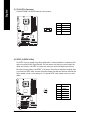
5) IDE1 (IDE Connector)
An IDE device connects to the computer via an IDE connector. One IDE connector can connect to
one IDE cable, and the single IDE cable can then connect to two IDE devices (hard drive or optical
drive). If you wish to connect two IDE devices, please set the jumper on one IDE device as Master
and the other as Slave (for information on settings, please refer to the instructions located on the IDE
device). Before attaching the IDE cable, please take note of the foolproof groove in the IDE connector.
2
40
1
39
Pin No. Definition
1 GND
2 +12V/Speed Control
3 Sense
4 Speed Control
Pin No. Definition
1 GND
2 +12V
3 Sense
CPU_FAN:
SYS_FAN:
Page is loading ...
Page is loading ...
Page is loading ...
Page is loading ...
Page is loading ...
Page is loading ...
Page is loading ...
Page is loading ...
Page is loading ...
Page is loading ...
Page is loading ...
Page is loading ...
Page is loading ...
Page is loading ...
Page is loading ...
Page is loading ...
Page is loading ...
Page is loading ...
Page is loading ...
Page is loading ...
Page is loading ...
Page is loading ...
Page is loading ...
Page is loading ...
Page is loading ...
Page is loading ...
Page is loading ...
Page is loading ...
Page is loading ...
Page is loading ...
Page is loading ...
Page is loading ...
Page is loading ...
Page is loading ...
Page is loading ...
Page is loading ...
Page is loading ...
Page is loading ...
Page is loading ...
Page is loading ...
Page is loading ...
Page is loading ...
Page is loading ...
Page is loading ...
Page is loading ...
Page is loading ...
Page is loading ...
Page is loading ...
Page is loading ...
Page is loading ...
Page is loading ...
Page is loading ...
Page is loading ...
Page is loading ...
Page is loading ...
Page is loading ...
Page is loading ...
Page is loading ...
Page is loading ...
Page is loading ...
-
 1
1
-
 2
2
-
 3
3
-
 4
4
-
 5
5
-
 6
6
-
 7
7
-
 8
8
-
 9
9
-
 10
10
-
 11
11
-
 12
12
-
 13
13
-
 14
14
-
 15
15
-
 16
16
-
 17
17
-
 18
18
-
 19
19
-
 20
20
-
 21
21
-
 22
22
-
 23
23
-
 24
24
-
 25
25
-
 26
26
-
 27
27
-
 28
28
-
 29
29
-
 30
30
-
 31
31
-
 32
32
-
 33
33
-
 34
34
-
 35
35
-
 36
36
-
 37
37
-
 38
38
-
 39
39
-
 40
40
-
 41
41
-
 42
42
-
 43
43
-
 44
44
-
 45
45
-
 46
46
-
 47
47
-
 48
48
-
 49
49
-
 50
50
-
 51
51
-
 52
52
-
 53
53
-
 54
54
-
 55
55
-
 56
56
-
 57
57
-
 58
58
-
 59
59
-
 60
60
-
 61
61
-
 62
62
-
 63
63
-
 64
64
-
 65
65
-
 66
66
-
 67
67
-
 68
68
-
 69
69
-
 70
70
-
 71
71
-
 72
72
-
 73
73
-
 74
74
-
 75
75
-
 76
76
-
 77
77
-
 78
78
-
 79
79
-
 80
80


Gigabyte GA-945PL-S3 User manual
- Category
- Motherboards
- Type
- User manual
Ask a question and I''ll find the answer in the document
Finding information in a document is now easier with AI
Related papers
-
Gigabyte GA-945PL-S3 User manual
-
Gigabyte GA-945GZM-S2 User manual
-
Gigabyte GA-G31MX-S2 User manual
-
-
Gigabyte NX6800GT-TD256E User manual
-
Gigabyte GA-M61VME-S2 Owner's manual
-
-
-
Gigabyte GA-EG31MF-S2 Owner's manual
-
Gigabyte GA-VM900M Owner's manual
Other documents
-
Intel GA-945PL-DS3P User manual
-
 Addonics Technologies ADEBIDE2SA User manual
-
AMD 701P47156 User manual
-
-
-
-
ECS 945PL-A User manual
-
-
Biostar 945PL-M7 Owner's manual
-
