
Instruction Manual
for model
FLOWMAX – 90
Nordgas Version
Condensing water heater
85,000 BTU
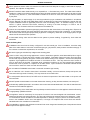
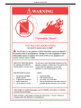
WARNING
If the information in these instructions is not followed exactly, a fire or explosion may result, causing property damage, personal injury or death.
-Do not store or use gasoline or other flammable vapours and liquids in the vicinity of this or any other appliance.
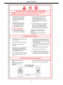
-WHAT TO DO IF YOU SMELL GAS
●Do not try to light any appliance.
●Do not touch any electrical switch; do not use any phone in your building.
●Immediately call your gas supplier from a neighbour’s phone. Follow the gas supplier’s instructions.
●If you cannot reach your gas supplier, call the fire department.
-Installation and service must be performed by a qualified installer, service agency or the gas supplier.
Installation, operating, commissioning and maintenance instructions.
Water heaters for other than recreational vehicle installation


CONTENTS
Pages
General information
1.1 General warnings 1
1.2 Product conformity 9
2. Technical characteristics
2.1 Technical data 10
2.2 Dimensions 11
2.3 Internal parts of the water heater 12
2.4 Water circuit 13
2.5 Circulation pump head/flow graph 14
2.6 Printed circuit board – Technical characteristics 15
2.7 Control panel 16
3. Installation (authorized personnel)
3.1 Reference standard 18
3.2 Unpacking 19
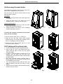
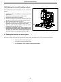
3.3 Installing the water heater 20
3.4 Water connections 21
3.5 Domestic Hot Water Circuit/Hard Water Warning/ Condensate Drain 22
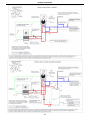
3.6 Schematic of Piping Installation 24
3.7 Gas connection 26
3.8 Electrical connections
27
3.9 Venting connections 29
4. Commissioning the appliance (authorized personnel)
4.1 General warnings 36
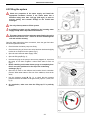
4.2 Filling the system 37
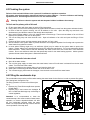
4.3 Flushing the system 38
4.4 Filling the condensate trap 38
4.5 Starting up the water heater 39
5. Regulating the appliance (authorized personnel)
5.1 Parameters table 40
5.2 Setting the parameters 42
5.3 Gas Data 51

CONTENTS
Pages
6. Maintenance (authorized personnel)
6.1 General warnings 52
6.2 Maintenance 52
6.3 Water heater inspection 52
6.4 Accessing the water heater 54
6.5 Flushing out the primary side 54
6.6 Draining the central heating and domestic hot water system 55
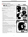
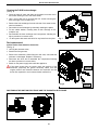
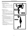
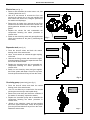
6.7 Maintenance operations 56
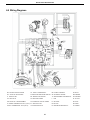
6.8 Wiring diagrams 63
6.9 D.H.W Sensor Connection 66
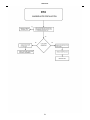
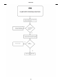
6.10 Troubleshooting 67
6.11 Diagnostics 68
6.12 Parts list 82
7. Warranty
7.1 Terms and Condition of Sale 84
7.2 Warranty Registration Form 86
7.3 Warranty Part Request Form 87

GENERAL INFORMATION
1
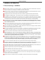
1. GENERAL INFORMATION
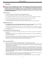
1.1 General warnings – Installation
Read all safety warnings in the “Instruction Manual”. The additional safety issues outlined below must also be
followed completely when installing this FLOWMAX Combination Water heater.
Failure to remove or maintain the area free of combustible material, gasoline and other flammable liquids or vapours
can result in severe personal injury, death or substantial property damage.
All applicable local, state, national and provincial codes, ordinances, regulations and laws must be observed.
For installations in Massachusetts – code requires the units to be installed by a licensed plumbing or gas fitter.
The appliance cannot operate without the correct amount of air for combustion. Please make sure there is sufficient
inflow and outflow of air for ventilation, never obstruct the flow of ventilation air. Failure to provide the proper amount
of combustion air can result in a fire or explosion and cause death, serious bodily injury or property damage.
If an external electrical source is utilized, the appliance, when installed, must be electrically grounded in accordance
with local codes or, in the absence of local codes, with the National Electrical Codes ANSI/NFPA 70 and or the CSA
C22.1 Canadian Electrical Code.
Follow all local codes and/or the most recent edition of the National Fuel Gas Code (ANSI Z223.1/NFPA 54) in the
USA or the Natural Gas and Propane Installation Code in Canada (CAN/CSA B149.1).
This unit is designed for indoor installations. DO NOT operate this unit without the vent piping connected. Exhaust
gases must be completely expelled out of the building.
Do not use this appliance if any part has been underwater. Immediately call a qualified service technician to inspect
the appliance and replace any part of the control system and any gas control which has been underwater.
Be sure not to reverse the water and gas connections as this may damage the gas valves.
Water temperatures over 125⁰F can cause severe burns instantly or death from scalding. If the proposed water
heater outlet temperature is above 125⁰F, a thermostatically controlled mixing valve (or a temperature limiting valve)
for reducing point of use water temperature is recommended to reduce the risk of scald injury. Contact a licensed
plumber or the local plumbing authority for further information.
The appliance should be located in an area where leakage within the unit or at its connections will not result in
damage to the area adjacent to the appliance or to lower floors of the structure. FLOWMAX will not be responsible
for any damage resulting from leaking if adequate drainage is not provided. When such locations cannot be
avoided, it is recommended that a suitable drain pan, adequately drained, be installed under the appliance.
Do not use this combination water heater for any purpose other than water heating and space heating.
The flow of combustion air and ventilation to the water heater must not be obstructed. The water heater area must
be kept clear and free from combustible materials, gasoline and other flammable vapours and liquids.
If the water quality is known to be highly acidic and/or extremely hard, water treatments (ie water softeners and
filtration) are recommended to maintain full warranty. Consult the local water authority.
DO NOT over-tighten fittings, as pipe and/or fitting damage may occur causing leakage.
DO NOT install water heater where subject to vibrations.
For other than a direct vent appliance, the appliance must be located as close as possible to a chimney or gas vent.
Should overheating occur or the gas supply fails to shut off, turn the manual gas control valve to the appliance.
Contact a Service Technician immediately.
Clearance must be in accordance with the local installation codes and the requirements of the gas supplier.

GENERAL INFORMATION
2
Never operate the heater unless it is vented to the outdoors and has adequate air supply to avoid risks of improper
operation, fire, explosion or asphyxiation.
DO NOT install this water heater directly on a carpeted floor. A fire hazard may result. The water heater shall be
installed on a metal or wood panel extending beyond the full width and depth of the water heater by at least 3 inches
(76.2mm) in any direction or, if the water heater is installed in an alcove or closet, the entire floor shall be covered
by the panel.
For safe operation, an ample supply of air must be provided for proper combustion and ventilation in accordance
with the National Fuel Gas Code ANSI Z223.1/NFPA 54 National Fuel Gas Code CSA/B149.1 Natural Gas and
Propane Installation Codes or applicable provisions of the local building codes. An insufficient supply of air may
result in a yellow, luminous burner flame, carboning or sooting of the heat exchanger, or create a risk of
asphyxiation. Do not obstruct the flow of combustion and ventilation air.
This unit is not intended to operate at gas supply pressures other than those shown on the rating plate. Exposure to
higher gas supply pressure may cause damage to gas valves, which can result in fire or explosion. If over-pressure
has occurred, such as through improper testing of gas lines or emergency malfunction of the supply system, the gas
valves must be checked for safe operation.
A thermostatic mixing valve must be added to this system to prevent scalding, if regulated by local codes and
authorities.
Check the Rating Plate
FLOWMAX units come from the factory configured for use with natural gas. Prior to installation, check the rating
plate of the water heater to ensure the unit matches gas type, gas pressure, water pressure and electrical supply. If
the unit does not match the requirements, do not install.
Be sure the gas type and electricity voltage match the rating plate.
There is a risk in using fuel burning appliances in rooms or areas where gasoline, other flammable liquids or engine-
driven equipment or vehicles are stored, operate or are repaired. Flammable vapours are heavy and travel along
the floor and may be ignited by the igniter or main burner flames causing fire or explosion. Some local codes permit
operation of gas appliances if installed 18 inches or more above the floor. This may reduce the risk if location in
such an area cannot be avoided. Flammable items, pressurized containers or any other potential fire hazardous
articles must never be placed on or adjacent to the water heater. Open containers of flammable materials should
not be stored or used in the same room with the water heater.
Do not install the FLOWMAX water heater in areas with excessive high humidity.
Do not install the unit in location where there is excessive humidity, such as a bathroom, damp crawl space, and
other areas with high levels of humidity. This may cause the unit to malfunction.
To avoid possible electrical shock, DO NOT touch the internal components of the water heater or the power cord
with wet hands.
DO NOT splash excessive water on the water heater when cleaning, as they are water resistant, not water proof.
Professionally qualified personnel in accordance with current laws and standards and in line with the manufacturer’s
instructions must install the appliance.
The commissioning of the water heater and any subsequent works carried out on the appliance must be effected by
an appropriately qualified technician.
The appliance must be used solely for the purpose for which it has been designed and manufactured: central
heating and domestic hot water production. Any other use is deemed as improper and as such dangerous. Under
no circumstances will the manufacturer be held responsible for damage or injury to persons or animals caused by
errors in the installation and/or use of the appliance, or through non-compliance with current local and national
standards and/or the manufacturer’s instructions.
The installation, operation and maintenance manual forms are an integral and essential part of the product and must
be kept with the appliance always.

GENERAL INFORMATION
3
The warnings contained in this chapter have been written for the appliance user, the installer and the service
technician.
The “operating instructions” chapter of this manual must be read carefully as it provides information on the operation
and the operating limits of the appliance.
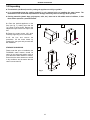
• After the removal of all the packaging, check that the appliance has not been damaged. In case of doubt, do not attempt
to use the product but refer to the supplier. Packing materials (cardboard box, wooden crate, nails, staples, plastic bags,
polystyrene, etc.) must not be left within reach of children in that these items represent a potential hazard and must be
disposed of in a responsible manner.
• Before carrying out any cleaning or maintenance operations, disconnect the appliance from the mains electricity supply by
switching off at the main switch and/or any other isolating device.
• In the case of a fault and/or malfunction in the appliance, shut down the system. Do not interfere with or attempt any
repairs. Call for professionally qualified technical assistance only.
• Any warranty repairs to the appliance must be carried out exclusively by the manufacturer’s authorized service dealers
using original spare parts. Non-compliance with the above requirements may compromise the safety of the appliance and
invalidate the warranty. In order to guarantee the efficiency of the appliance and its correct operation, it must be serviced
regularly by professionally qualified personnel in line with the manufacturer’s instructions.
• Only original accessories or optional extras (including electrical parts) must be used with the appliance.
• Should there be a smell of gas present in the room where the appliance is installed, DO NOT attempt to activate any
electric switches, telephones or any other equipment that may cause sparks. Open doors and windows immediately to
create a current of air and ventilate the room. Shut-off the main gas supply valve (at the meter), or on the cylinder in the
case of bottled gas, and call an authorized service centre.
• Do not attempt to interfere with the appliance in any way.
• As dictated by current legislation, this appliance must be installed exclusively by qualified personnel. Before starting
the water heater for the first time, make sure that it is connected to a water supply and central heating system compatible
with its performance characteristics.
• Prior to start-up, the central heating pipes should be flushed to remove any residues that could compromise the operation
of the appliance.
• The domestic power supply must be checked by a qualified electrician to ensure that it can support the maximum power
absorption of the appliance, as indicated on the appliance rating plate (positioned on the casing). In particular, make sure
that the cable ratings are adequate for the power absorbed.
• Do not use adapters; multiple sockets or extension leads to connect the appliance to the power supply.
• The appliance must be connected to the mains power supply through an appropriate electrical isolator in accordance with
the current wiring regulations.
• If the cable is damaged in any way, switch off the appliance and have the cable replaced by a suitably qualified
technician.
• When the appliance is no longer required for use, switch off the main power supply, to switch all electrical
components off (circulating pump, burner etc.).

GENERAL INFORMATION
4
Important: Carbon Monoxide Detectors
Many jurisdictions require the installation of carbon monoxide detectors in building where a side wall vented fuel burning
appliance is installed. Installers must abide by local code requirements regarding the installation of CO detectors. The use of
a certified carbon monoxide detector is recommended but not required by FLOWMAX.
“In the State of Massachusetts only”
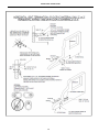
(a)For all horizontally vented gas fuelled equipment installed in every dwelling, building or structure used in whole or in part
for residential purposes, including those owned and operated by the Commonwealth and where the side wall exhaust vent
termination is less than seven (7) feet above finished grade in the area of the venting, including but not limited to decks and
porches, the following requirements shall be satisfied:
1. INSTALLATION OF CARBON MONOXIDE DETECTORS. At the time of installation of the side wall horizontal
vented gas fuelled equipment, the installing plumber or gas fitter shall observe that a hard wired carbon
monoxide detector
with an alarm and battery back-up is installed on the floor level where the gas equipment
is to be installed and on each additional level of the dwelling, building or structure served by the equipment. It
shall be the responsibility of the property owner to secure the services of qualified licensed professionals for the
installation of hard wired carbon monoxide detectors.
a. In the event that the side wall horizontally vented gas fuelled equipment is installed in a crawl space or
an attic, the hard wired carbon monoxide detector with alarm and battery back-up may be installed on
the next adjacent floor level.
b. In the event that the requirements of this subdivision cannot be met at the time of completion of
installation, the owner shall have a period of 30 days to comply with the above requirements; provided,
however, that during said 30 day period a battery operated carbon monoxide detector with alarm shall
be installed.
2. APPROVED CARBON MONOXIDE DETECTORS. Each carbon monoxide detector as required in accordance
with the above provisions shall comply with NFPA 720 and be ANSI/UL 2034 listed and IAS certified.
3. SIGNAGE. A metal or plastic identification plate shall be permanently mounted to the exterior of the building at a
minimum height of eight (8) feet above grade directly in line with the exhaust vent terminal for the horizontally
vented gas fuelled heating appliance or equipment. The sign shall read, in print size no less than one-half (1/2)
inch in size, “GAS VENT DIRECTLY BELOW. KEEP CLEAR OF ALL OBSTRUCTIONS”.
4. INSPECTION. The state or local gas inspector of the side wall horizontally vented gas fuelled equipment shall
not approve the installation unless, upon inspection, the inspector observes carbon monoxide detectors and
signage installed in accordance with the provisions of 248 CMR 5.08(2)(a) 1 through 4.

GENERAL INFORMATION
5

GENERAL INFORMATION
6

GENERAL INFORMATION
7

GENERAL INFORMATION
8

GENERAL INFORMATION
9
1.2 Product conformity
All FLOWMAX water heaters are ETL certified and possess technical and functional characteristics that comply with
the following standards:
Gas fired water heaters also comply with the following standards:
American National Standard/CSA Standard for Gas Water Heaters Volume III, Storage Water Heaters with input
Ratings above 75,000 Btu per Hour, Circulating and Instantaneous. Conforms to ANSI STD Z21.10.3, certified to CSA
STD 4.3.
The materials used such as copper, brass, stainless steel, etc. form a compact, uniform, highly functional unit that is
easy to install and simple to operate. In its simplicity, the wall-mounted appliance is equipped with all the appropriate
accessories required to make it a fully independent water heater capable of satisfying domestic hot water production
and central heating needs. All water heaters are fully inspected and are accompanied by a quality certificate, signed by
the inspector, and a guarantee certificate. This manual must be kept in a safe place and must accompany the water
heater at all times.
FLOWMAX will not be held responsible for any misinterpretation of this manual resulting from the inaccurate
translation of same.
FLOWMAX will not be held responsible for the consequences in the case of non-observance of the
instructions contained in this manual or in the case where actions not specifically described herein are
undertaken.

GENERAL INFORMATION
10
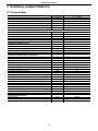
2. TECHNICAL CHARACTERISTICS
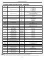
2.1 Technical data
Model
FLOWMAX - 90
Heat Input max
kW - BTU/hr
25 – 90 000
Heat Input min
kW - BTU/hr
9 – 35 000
Heat Output max - 122/86°F
kW - BTU/hr
26.7 – 91 019
Heat Output max - 167/140°F
kW - BTU/hr
24.6 – 83 939
Heat Output min - 167/140°F
kW - BTU/hr
8.73 – 29 788
Efficiency 100% (full load 167/140°F)
%
98.4
Central Heating circuit
Central Heating water temperature setting (min-max)
°C – °F
25–40 / 30-75 - 77–104 / 86-167
Max. heating working temperature
°C – °F
75/167
Expansion vessel capacity
ltrs - gal
6 - 1.58
Max. working pressure (heating)
bar - psi
2.1 - 30
Min. working pressure (heating)
bar - psi
0.3 - 4.29
Domestic Hot Water circuit
D.H.W. temperature setting (min-max)
°C – °F
35-72 – 95-160
Max. Hot water working pressure
bar - psi
6 - 86
Min. Hot water working pressure
bar - psi
0.5 - 7.16
D.H.W. flow rate at ∆T 45°F (25°C)
l/min - gal/min
14.10 - 3.72
D.H.W. flow rate at ∆T 72°F (40°C)
l/min - gal/min
8.7 - 2.30
Dimensions (Water heater casing size)
Width
in
16.1
Height
in
28.7
Depth
in
11.2
Weight (net)
lb
84
Hydraulic connections
Central Heating Flow connection
BSPP
3/4"
Central heating Return connection
BSPP
3/4"
Cold water mains connection
BSPP
1/2"
D. Hot water connection
BSPP
1/2"
Gas connection
NPT
1/2"
Gas Supply
Natural Gas (Ng)
Inlet pressure
mbar – in wc
20 - 7
Gas consumption
m
3
/h - ft
3
/h
2.65 - 93.58
Liquid Propane (Lp)
Inlet pressure
mbar – in wc
37 – 14
Gas Consumption
m
3
/h - ft
3
/h
1.01 – 35.67
Electrical specifications
Power supply
V/Hz
120/60
Electrical power consumption
W
180

GENERAL INFORMATION
11
4.3
5.4
6.4
11.2
5.2
28.7
HO
CWI
G
HI
HWO
1.9 3.1
4
1.2
11.2
28.7
4.4
7.3
4.4
1.9
12.3
1.9
4.1
2.7
3.2
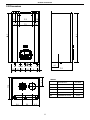
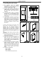
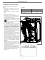
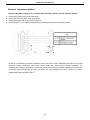
2.2 Dimensions
LEGEND
HI
HEATING INLET
3/4" BSPP
HO
HEATING OUTLET
3/4" BSPP
G
GAS
1/2" BSPP
CWI
COLD WATER INLET
1/2" BSPP
HWO
HOT WATER OUTLET
1/2" BSPP
SC
CONDENSATE DRAIN
0.98 in

GENERAL INFORMATION
12
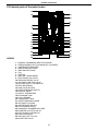
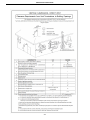
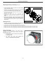
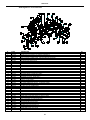
2.3 Internal parts of the water heater
LEGEND
1. PRIMARY CONDENSING HEAT EXCHANGER
2. PREMIX BURNER UNIT (GAS MANIFOLD + BURNER)
3. CONDENSATE DRAIN PIPE
4. IONIZATION ELECTRODE
5. IGNITION ELECTRODE
6. FAN
7. VENTURI
8. IGNITION TRANSFORMER
9. ELECTRONIC GAS VALVE
10. PRESSURE RELIEF VALVE
11. AUTOMATIC AIR VENT VALVE
12. HEATING SAFETY THERMOSTAT
13. HEATING SENSOR
14. PUMP WITH AIR VENT
15. WATER PRESSURE SWITCH
16. EXHAUST HOOD
17. SAFETY THERMOFUSE
18. EXPANSION TANK
19. D.H.W. SENSOR
20. CONDENSATE TRAP
21. WATER PRESSURE GAUGE
22. AUTOMATIC BY-PASS
23. AIR PRESSURE SWITCH
24. SYSTEM DRAIN VALVE
25. ROOM SEAL CHAMBER BACK SIDE
26. DIVERTER ACTUATOR VALVE
27. ELECTRONIC FLOWSWITCH
28. DHW EXCHANGER
29. HEATING LOOP FILL TAP
30. NO-RETURN VALVE
13
24
17
3
2
16
19
20
1
12
7
6
10
14
22
11
4
29
25
5
15
9
18
28
26
27
21
30
8
23

GENERAL INFORMATION
13
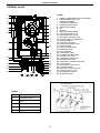
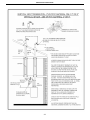
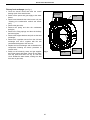
2.4 Water circuit
LEGEND
1. PRIMARY CONDENSING HEAT EXCHANGER
2. PREMIX BURNER UNIT (GAS
MANIFOLD+BURNER)
3. CONDENSATE DRAIN PIPE
4. IONIZATION ELECTRODE
5. IGNITION ELECTRODE
6. FAN
7. VENTURI
8. IGNITION TRANSFORMER
9. ELECTRONIC GAS VALVE
10. PRESSURE RELIEF VALVE
11. AUTOMATIC AIR VENT VALVE
12. HEATING SAFETY THERMOSTAT
13. HEATING SENSOR
14. PUMP WITH AIR VENT
15. WATER PRESSURE SWITCH
16. EXHAUST HOOD
17. SAFETY THERMO FUSE
18. EXPANSION TANK
19. D.H.W. SENSOR
20. CONDENSATE TRAP
21. WATER PRESSURE GAUGE
22. AUTOMATIC BY-PASS
23. CONDENSATE DRAIN PIPE
24. SYSTEM DRAIN VALVE
25. ROOM SEAL CHAMBER BACK SIDE
26. FLOW LIMITER
27. ELECTRONIC FLOWSWITCH
28. DHW EXCHANGER
29. DIVERTER ACTUATOR VALVE
30. HEATING LOOP FILL TAP
31. AIR PRESSURE SWITCH
32. NO-RETURN VALVE
LEGEND
HI
HEATING INLET
HO
HEATING OUTLET
G
GAS
CWI
COLD WATER INLET
HWO
HOT WATER OUTLET
SC
CONDENSATE DRAIN
3
19
22
21
SC
23
25
18
17
2
16
19
5
4
6
9
20
11
10
24
14
15
27
29
28
13
1
12
7
30
32
26
HWO CWIG
31
8
HI HO

GENERAL INFORMATION
14
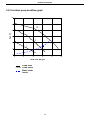
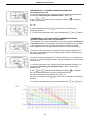
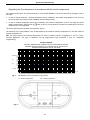
2.5 Circulation pump head/flow graph
Pump head
I, II, III
Pump speed
Water heater
losses
I
II
III
0
5
10
15
20
25
30
0 2
4 6 8
10
Water flow (US gpm)
Head (ft)

GENERAL INFORMATION
15
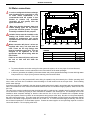
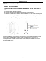
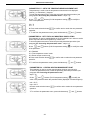
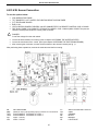
2.6
DIGITECH CS MIAH4 COD.40-0007
MAIN NEWS
The new electronic board Digitech CS is now installed on all condensing boiler models, from the 13kW output
model to the 100kw output model.
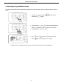
At the first ignition of the boiler, the function F33 (System purging function) is enable for a period of 5 minutes;
the
pump is enabled while the burner ignition is disable. This cycle eliminates any residual air contained in the system.
The same function is automatically enabled every time the E04 error (no water in the system) appears
on the
display, activated by the water pressure switch, in this case for a period of 2 minutes.
Other news:
•
White backlit LCD Display;
•
Improved icons graphic for an easy reading and setting of the electronic board
•
The electronic board manages the zone control PCB from the boiler control panel (only with zone PCB
in
stalled)
•
The flame presence signal is completed by the power level expressed in 3 steps.
•
Through the INFO button “i”
,
with boiler in OFF position, it is possible to display the last 5 errors (to reset
press "R " button).
Here below a list of possible settings to be performed, according to the specific need, by the authorized
technical
personnel:
•
Central heating temperature minimum and maximum set point adjustment from min 25°C to max 88°C
(factory set as 30-80°C).
•
Domestic Hot water temperature minimum and maximum set point adjustment from a min. 35°C to a
max
75°C (factory set at 35-60°C) ;
•
∆t set point flow I return (only if a modulating pump and sensor on the return circuit are installed);
•
Minimum and maximum speed of modulating pump (if installed);
With boiler in ON position, through the INFO button “i” (Info), it is now possible to display the following
information:
•
Outdoor temperature (if the outdoor temperature sensor is installed);
•
Kd value of outdoor temperature sensor (if installed);
•
Low temperature circuit temperature (if optional CRAD board for the 2 temperature circuits is
connected);
•
Solar panel sensor temperature (if installed);
•
Solar storage cylinder sensor temperature (if installed);
•
Fan speed.
The chimney-sweeper function (or test function) is enabled by keeping the button "R" (Reset) pressed for 7
seconds.

GENERAL INFORMATION
16
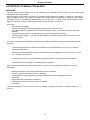
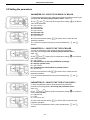
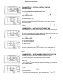
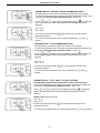
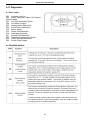
2.7 Control panel
Control panel Key
1.
HEATING TEMPERATURE SETTING BUTTONS
2.
INFO BUTTON: PRESS ONCE TO DISPLAY
TEMPERATURES AND INFO (see 2.8 INFO menu
display). KEEP INFO BUTTON PRESSED FOR 5
SECONDS (in OFF MODE) TO DISPLAY
THE
LAST 5 ERRORS.
3
.
MODE SELECTION BUTTON
SUMMER ONLY I
WINTER ONLY I SUMMER-WINTER I OFF.
4.
RESET BUTTON:
ERROR RESET
-
FLUE TEST
FUNCTION ACTIVATION (CHIMNEY-SWEEPER
- KEEP IT PRESSED FOR 7 SECONDS).
5.
DOMESTIC HOT WATER TEMPERATURE
SETTING BUTTONS.
KEEP BUTTONS
'+'
AND
'-'
PRESSED FOR 5 SECONDS TO ACTIVATE
THE
DISPLAY BACKLIT MODE FOR A
CONTINUOUS
PERIOD OF 10 MINUTES.
6.
TERMINAL BLOCK FOR EXTERNAL WIRING.
7.
LCD DISPLAY.
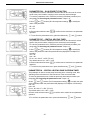
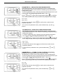
LCD DISPLAY ICONS' KEY
1. PARAMETER NUMBER INFORMATION
2.
PARAMETERS PROGRAMMING MODE ON
3.
SOLAR PCB CONNECTION INFORMATION I
SOLAR PANEL TEMPERATURE DISPLAY (d6)
4.
SOLAR PUMP ON
5.
STORAGE CYLINDER LOW LEVEL
TEMPERATURE VISUALIZATION (d7)
I
STORAGE
CYLINDER HIGH LEVEL TEMPERATURE
VISUALIZATION (dB)
6. OUTDOOR TEMPERATURE SENSOR
CONNECTED I OUTDOOR SENSOR
TEMPERATURE DISPLAY (d2)
7.
TEMPERATURE I SET POINT I PARAMETER
VALUE INFORMATION
8.
OPEN THERM COMPONENTS COMMUNICATION
CONNECTED (REMOTE
CONTROL I ZONE
MANAGEMENT CONTROL BOX)
9. WATER LOW PRESSURE INFORMATION
10.
(*) FLAME PRESENCE ON (3 POWER STEPS)
11.
D.H.W. MODE ENABLED
12.
RESETTABLE ERROR DISPLAY
13.
OFF MODE
14.
NOT RESETTABLE ERROR DISPLAY
15.
HEATING MODE ENABLED
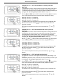
10
(*) -
During the boiler operation the display
can show 3 different power levels according to
the flame modulation
of the boiler. (See flame
icon/power % images
>33% >33%<66% >66%<100%
120v 60Hz
Page is loading ...
Page is loading ...
Page is loading ...
Page is loading ...
Page is loading ...
Page is loading ...
Page is loading ...
Page is loading ...
Page is loading ...
Page is loading ...
Page is loading ...
Page is loading ...
Page is loading ...
Page is loading ...
Page is loading ...
Page is loading ...
Page is loading ...
Page is loading ...
Page is loading ...
Page is loading ...
Page is loading ...
Page is loading ...
Page is loading ...
Page is loading ...
Page is loading ...
Page is loading ...
Page is loading ...
Page is loading ...
Page is loading ...
Page is loading ...
Page is loading ...
Page is loading ...
Page is loading ...
Page is loading ...
Page is loading ...
Page is loading ...
Page is loading ...
Page is loading ...
Page is loading ...
Page is loading ...
Page is loading ...
Page is loading ...
Page is loading ...
Page is loading ...
Page is loading ...
Page is loading ...
Page is loading ...
Page is loading ...
Page is loading ...
Page is loading ...
Page is loading ...
Page is loading ...
Page is loading ...
Page is loading ...
Page is loading ...
Page is loading ...
Page is loading ...
Page is loading ...
Page is loading ...
Page is loading ...
Page is loading ...
Page is loading ...
Page is loading ...
Page is loading ...
Page is loading ...
Page is loading ...
Page is loading ...
Page is loading ...
Page is loading ...
Page is loading ...
Page is loading ...
Page is loading ...
Page is loading ...
-
 1
1
-
 2
2
-
 3
3
-
 4
4
-
 5
5
-
 6
6
-
 7
7
-
 8
8
-
 9
9
-
 10
10
-
 11
11
-
 12
12
-
 13
13
-
 14
14
-
 15
15
-
 16
16
-
 17
17
-
 18
18
-
 19
19
-
 20
20
-
 21
21
-
 22
22
-
 23
23
-
 24
24
-
 25
25
-
 26
26
-
 27
27
-
 28
28
-
 29
29
-
 30
30
-
 31
31
-
 32
32
-
 33
33
-
 34
34
-
 35
35
-
 36
36
-
 37
37
-
 38
38
-
 39
39
-
 40
40
-
 41
41
-
 42
42
-
 43
43
-
 44
44
-
 45
45
-
 46
46
-
 47
47
-
 48
48
-
 49
49
-
 50
50
-
 51
51
-
 52
52
-
 53
53
-
 54
54
-
 55
55
-
 56
56
-
 57
57
-
 58
58
-
 59
59
-
 60
60
-
 61
61
-
 62
62
-
 63
63
-
 64
64
-
 65
65
-
 66
66
-
 67
67
-
 68
68
-
 69
69
-
 70
70
-
 71
71
-
 72
72
-
 73
73
-
 74
74
-
 75
75
-
 76
76
-
 77
77
-
 78
78
-
 79
79
-
 80
80
-
 81
81
-
 82
82
-
 83
83
-
 84
84
-
 85
85
-
 86
86
-
 87
87
-
 88
88
-
 89
89
-
 90
90
-
 91
91
-
 92
92
-
 93
93


FLOWMAX Technologies 120 User manual
- Type
- User manual
- This manual is also suitable for
Ask a question and I''ll find the answer in the document
Finding information in a document is now easier with AI
Other documents
-
Rheem PRO+G75T-75N CN62 PDV User guide
-
 SOLARIVER SRK20360 User guide
-
Guardian GLD1 Operating instructions
-
Radiant RKA 20 User manual
-
 PRO ELEC PEL01220 Operating instructions
-
Country Comfort JSD12-D6N Instructions Manual
-
BALTUR Minicomist 7 User manual
-
Vetus VH4.65/4.80 Installation guide
-
Danfoss ALL IN ONE Type Air-source Heat Pump Water Heater Installation guide
-
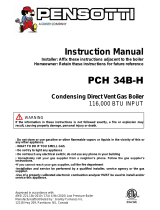 Pensotti PCH 34B-H User manual


