WinSystems SBC35-CC405-3845 User manual
- Category
- Motherboards
- Type
- User manual
This manual is also suitable for

WinSystems, Inc. | 715 Stadium Drive, Arlington, Texas 76011 | 817-274-7553 | [email protected] | www.winsystems.com
SBC35-CC405
Industrial Intel
®
Atom™ SFF Computer
with Expansion
Product Manual

SBC35-CC405
v1.0 www.winsystems.com Page i
Revision History
Copyright and Trademarks
Copyright 2016, WinSystems, Inc.
No part of this document may be copied or reproduced in any form or by any means
without the prior written consent of WinSystems, Inc. The information in the document
is subject to change without notice. The information furnished by WinSystems, Inc. in
this publication is believed to be accurate and reliable. However, WinSystems, Inc.
makes no warranty, express, statutory, implied or by description, regarding the
information set forth herein or regarding the freedom of the described devices from
patent infringement. WinSystems, Inc. makes no warranty of merchantability or fitness
for any purpose. WinSystems, Inc. assumes no responsibility for any errors that may
appear in this document.
Trademark Acknowledgments
WinSystems is a registered trademark of WinSystems, Inc.
Duo-Clasp™ and Pico-Clasp™ are registered trademarks of Molex, Inc.
Phoenix SecureCore™ is a registered trademark of Phoenix Technologies Ltd.
Document
Version
Last Updated
Date
Brief Description of Change
v1.0 12/2016 Initial release

SBC35-CC405
v1.0 www.winsystems.com Page ii
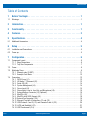
Table of Contents
1 Before You Begin . . . . . . . . . . . . . . . . . . . . . . . . . . . . . . . . . . . . . . . . . 1
1.1 Warnings . . . . . . . . . . . . . . . . . . . . . . . . . . . . . . . . . . . . . . . . . . . . . . . . . . . . . . . . . . . . . . . . . . . . . . 1
2 Introduction. . . . . . . . . . . . . . . . . . . . . . . . . . . . . . . . . . . . . . . . . . . . . 1
3 Functionality . . . . . . . . . . . . . . . . . . . . . . . . . . . . . . . . . . . . . . . . . . . . 1
4 Features . . . . . . . . . . . . . . . . . . . . . . . . . . . . . . . . . . . . . . . . . . . . . . . 2
5 Specifications . . . . . . . . . . . . . . . . . . . . . . . . . . . . . . . . . . . . . . . . . . . 4
5.1 Additional Accessories . . . . . . . . . . . . . . . . . . . . . . . . . . . . . . . . . . . . . . . . . . . . . . . . . . . . . . . . . . . . 4
6 Setup . . . . . . . . . . . . . . . . . . . . . . . . . . . . . . . . . . . . . . . . . . . . . . . . . 5
6.1 Installation and Connections . . . . . . . . . . . . . . . . . . . . . . . . . . . . . . . . . . . . . . . . . . . . . . . . . . . . . . . 5
6.2 Power up . . . . . . . . . . . . . . . . . . . . . . . . . . . . . . . . . . . . . . . . . . . . . . . . . . . . . . . . . . . . . . . . . . . . . . 5
7 Configuration. . . . . . . . . . . . . . . . . . . . . . . . . . . . . . . . . . . . . . . . . . . . 6
7.1 Component Layout. . . . . . . . . . . . . . . . . . . . . . . . . . . . . . . . . . . . . . . . . . . . . . . . . . . . . . . . . . . . . . . 6
7.1.1 Edge Connections. . . . . . . . . . . . . . . . . . . . . . . . . . . . . . . . . . . . . . . . . . . . . . . . . . . . . . . . . . 6
7.1.2 Top View Components . . . . . . . . . . . . . . . . . . . . . . . . . . . . . . . . . . . . . . . . . . . . . . . . . . . . . . 7
7.2 Power. . . . . . . . . . . . . . . . . . . . . . . . . . . . . . . . . . . . . . . . . . . . . . . . . . . . . . . . . . . . . . . . . . . . . . . . . 9
7.3 Watchdog Timer. . . . . . . . . . . . . . . . . . . . . . . . . . . . . . . . . . . . . . . . . . . . . . . . . . . . . . . . . . . . . . . . . 9
7.3.1 Example code (C WDT) . . . . . . . . . . . . . . . . . . . . . . . . . . . . . . . . . . . . . . . . . . . . . . . . . . . . 11
7.3.2 Example Code: Basic . . . . . . . . . . . . . . . . . . . . . . . . . . . . . . . . . . . . . . . . . . . . . . . . . . . . . . 12
7.4 Connectors. . . . . . . . . . . . . . . . . . . . . . . . . . . . . . . . . . . . . . . . . . . . . . . . . . . . . . . . . . . . . . . . . . . . 12
7.4.1 SATA Power (J1) . . . . . . . . . . . . . . . . . . . . . . . . . . . . . . . . . . . . . . . . . . . . . . . . . . . . . . . . . 12
7.4.2 HD Audio 7.1 Surround (J2). . . . . . . . . . . . . . . . . . . . . . . . . . . . . . . . . . . . . . . . . . . . . . . . . 13
7.4.3 Serial ATA (J3) . . . . . . . . . . . . . . . . . . . . . . . . . . . . . . . . . . . . . . . . . . . . . . . . . . . . . . . . . . . 14
7.4.4 System Management (J4) . . . . . . . . . . . . . . . . . . . . . . . . . . . . . . . . . . . . . . . . . . . . . . . . . . 14
7.4.5 Power Input (J5) . . . . . . . . . . . . . . . . . . . . . . . . . . . . . . . . . . . . . . . . . . . . . . . . . . . . . . . . . 15
7.4.6 Stereo Audio: Line-In, Line-Out, and Microphone (J6). . . . . . . . . . . . . . . . . . . . . . . . . . . . . 16
7.4.7 External Battery Connector (J7) (Optional). . . . . . . . . . . . . . . . . . . . . . . . . . . . . . . . . . . . . . 16
7.4.8 MiniPCIe (J8) . . . . . . . . . . . . . . . . . . . . . . . . . . . . . . . . . . . . . . . . . . . . . . . . . . . . . . . . . . . . 17
7.4.9 MiniPCIe with SATA Support (J9) . . . . . . . . . . . . . . . . . . . . . . . . . . . . . . . . . . . . . . . . . . . . 18
7.4.10 External Fan Connector (J10). . . . . . . . . . . . . . . . . . . . . . . . . . . . . . . . . . . . . . . . . . . . . . . . 19
7.4.11 Ethernet (Top Half of Connectors J11 and J13) . . . . . . . . . . . . . . . . . . . . . . . . . . . . . . . . . . 19
7.4.12 USB Channels 1 and 3 (J11) and Channels 2 and 4 (J13) . . . . . . . . . . . . . . . . . . . . . . . . . . 20
7.4.13 LVDS and Backlight (J12) . . . . . . . . . . . . . . . . . . . . . . . . . . . . . . . . . . . . . . . . . . . . . . . . . . 21
7.4.14 USB Touchscreen (J14) . . . . . . . . . . . . . . . . . . . . . . . . . . . . . . . . . . . . . . . . . . . . . . . . . . . . 22

SBC35-CC405
v1.0 www.winsystems.com Page iii
7.4.15 Display Port 1.1 (J15) . . . . . . . . . . . . . . . . . . . . . . . . . . . . . . . . . . . . . . . . . . . . . . . . . . . . . 22
7.4.16 IO60 Expansion (J16). . . . . . . . . . . . . . . . . . . . . . . . . . . . . . . . . . . . . . . . . . . . . . . . . . . . . . 23
7.4.17 COM 1 and COM 2 (J19A and J19B) . . . . . . . . . . . . . . . . . . . . . . . . . . . . . . . . . . . . . . . . . . 24
7.4.18 Ethernet GPIO Controller (J20). . . . . . . . . . . . . . . . . . . . . . . . . . . . . . . . . . . . . . . . . . . . . . . 24
7.4.19 Analog VGA (J21). . . . . . . . . . . . . . . . . . . . . . . . . . . . . . . . . . . . . . . . . . . . . . . . . . . . . . . . . 25
7.4.20 CFAST (SATA SSD) (J103). . . . . . . . . . . . . . . . . . . . . . . . . . . . . . . . . . . . . . . . . . . . . . . . . . 26
7.5 Jumpers . . . . . . . . . . . . . . . . . . . . . . . . . . . . . . . . . . . . . . . . . . . . . . . . . . . . . . . . . . . . . . . . . . . . . . 26
7.5.1 Fan Voltage Output (JP2) . . . . . . . . . . . . . . . . . . . . . . . . . . . . . . . . . . . . . . . . . . . . . . . . . . . 26
7.5.2 Battery Select (JP3) . . . . . . . . . . . . . . . . . . . . . . . . . . . . . . . . . . . . . . . . . . . . . . . . . . . . . . . 27
7.5.3 Bits Per Pixel (JP4) . . . . . . . . . . . . . . . . . . . . . . . . . . . . . . . . . . . . . . . . . . . . . . . . . . . . . . . 27
7.5.4 LVDS Configuration (JP5) . . . . . . . . . . . . . . . . . . . . . . . . . . . . . . . . . . . . . . . . . . . . . . . . . . 27
7.5.5 Panel Orientation (JP6) . . . . . . . . . . . . . . . . . . . . . . . . . . . . . . . . . . . . . . . . . . . . . . . . . . . . 28
7.5.6 Backlight Power (JP7) . . . . . . . . . . . . . . . . . . . . . . . . . . . . . . . . . . . . . . . . . . . . . . . . . . . . . 28
7.5.7 Ethernet GPIO Reference Voltage Selection (JP8) . . . . . . . . . . . . . . . . . . . . . . . . . . . . . . . . 29
7.5.8 Basic Input/Output System (BIOS) Programming Defaults (JP9). . . . . . . . . . . . . . . . . . . . . 29
7.6 Switches. . . . . . . . . . . . . . . . . . . . . . . . . . . . . . . . . . . . . . . . . . . . . . . . . . . . . . . . . . . . . . . . . . . . . . 29
7.6.1 Power Button (SW1) . . . . . . . . . . . . . . . . . . . . . . . . . . . . . . . . . . . . . . . . . . . . . . . . . . . . . . 29
7.6.2 Reset Button (SW2) . . . . . . . . . . . . . . . . . . . . . . . . . . . . . . . . . . . . . . . . . . . . . . . . . . . . . . . 30
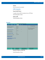
8 BIOS Settings . . . . . . . . . . . . . . . . . . . . . . . . . . . . . . . . . . . . . . . . . . 31
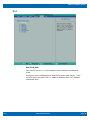
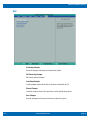
8.1 General Information . . . . . . . . . . . . . . . . . . . . . . . . . . . . . . . . . . . . . . . . . . . . . . . . . . . . . . . . . . . . . 31
8.2 Entering Setup . . . . . . . . . . . . . . . . . . . . . . . . . . . . . . . . . . . . . . . . . . . . . . . . . . . . . . . . . . . . . . . . . 31
8.3 Navigation of the Menus. . . . . . . . . . . . . . . . . . . . . . . . . . . . . . . . . . . . . . . . . . . . . . . . . . . . . . . . . . 31
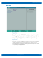
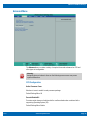
8.4 BIOS Splash Screen . . . . . . . . . . . . . . . . . . . . . . . . . . . . . . . . . . . . . . . . . . . . . . . . . . . . . . . . . . . . . 31
8.5 BIOS Screens . . . . . . . . . . . . . . . . . . . . . . . . . . . . . . . . . . . . . . . . . . . . . . . . . . . . . . . . . . . . . . . . . . 31
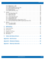
9 Cables and Software Drivers . . . . . . . . . . . . . . . . . . . . . . . . . . . . . . . . 48
Appendix A. Best Practices . . . . . . . . . . . . . . . . . . . . . . . . . . . . . . . . . . . . 49
Appendix B. Mechanical Drawing . . . . . . . . . . . . . . . . . . . . . . . . . . . . . . . 52
Appendix C. Warranty Information . . . . . . . . . . . . . . . . . . . . . . . . . . . . . . . 53

SBC35-CC405/Before You Begin
v1.0 www.winsystems.com Page 1
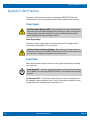
1. Before You Begin
Review the warnings (in this section) and the best practice recommendations (see “Best
Practices” on page 49) when using and handling the WinSystems SBC35-CC405.
Adherence to these recommendations provides an optimal user experience and
prevents damage. Read through this document and become familiar with the SBC35-
CC405 before proceeding.
1.1 Warnings
Only qualified personnel should configure and install the SBC35-CC405. While
observing the best practices, pay particular attention to the following:
2. Introduction
This manual provides configuration and usage information for the SBC35-CC405. If you
still have questions, contact Technical Support at (817) 274-7553, Monday through
Friday, between 8 AM and 5 PM Central Standard Time (CST).
Refer to the WinSystems website for other accessories (including cable drawings and
pinouts) that can be used with your SBC35-CC405.
3. Functionality
The SBC35-CC405 is a high-performance, industrial, small form factor (SFF) Single
Board Computer (SBC) capable of operating at high temperatures without a fan or heat-
pipe. The processor for the unit is an Intel
®
E3800 series Atom
™
, integrated into the
SBC35-CC405 using a Type 6 COM Express module. The low-profile thermal solution
provides a rugged platform base that protects the PCB assembly and offers convenient
four-point mounting. Information to configure and operate the SBC35-CC405 for most
FAILING TO COMPLY WITH THESE BEST PRACTICES MAY DAMAGE THE
SBC35-CC405 AND VOID YOUR WARRANTY.
Avoid Electrostatic Discharge (ESD)
Only handle the circuit board and other bare electronics when electrostatic discharge
(ESD) protection is in place. Having a wrist strap and a fully grounded workstation is
the minimum ESD protection required before the ESD seal on the product bag is
broken.
Warning
Do not reverse the positive and negative terminals when you connect power to the
unit. This will void the warranty and damage the board.

SBC35-CC405/Features
v1.0 www.winsystems.com Page 2
applications is included in this User Manual or on our website at
www.winsystems.com
.
NOTE WinSystems can provide custom configurations for Original Equipment Manufacturer
(OEM) clients. For details, please contact an Application Engineer through Technical
Support (see contact information in the Introduction section on page 1).
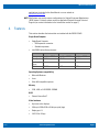
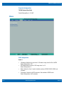
4. Features
This section describes the features that are included with the SBC35-CC405.
Single Board Computer
• Single Board Computer
– IO60 expansion connector
– Stackable expansion
• Intel E3800 series Atom processor:
Operating Systems (compatibility)
• Microsoft Windows
•Linux
• Other x86-compatible systems
Memory
• 2 GB, 4 GB, or 8 GB DDR3L SDRAM
BIOS
• Phoenix SecureCore™
Video Interfaces
• Up to two active displays
• VGA up to 2560x1536 at 24 bits per pixel (bpp)
• Display port 1.1
• LVDS 18 or 24 bpp
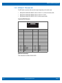
SBC35-CC405-3815 SBC35-CC405-3827 SBC35-CC405-3845
Processor Intel Atom E3815 Intel Atom E3827 Intel Atom E3845
Core Speed 1.46 GHz 1.75 GHz 1.91 GHz
Number of
Cores
124
L2 Cache 512 KB 1 MB 2 MB

SBC35-CC405/Features
v1.0 www.winsystems.com Page 3
Ethernet
• Two Intel
®
I210 Gigabit Ethernet (1 gigabit per second, GbE) controllers
Storage (Bootable)
• One SATA (2.0) channel
• One CFAST socket (on back of the board)
• One mSATA socket (MiniPCIe socket)
Serial Interface
• Two serial ports (RS-232/422/485)
• One USB 3.0 port
• Three USB 2.0 ports
Bus Expansion
• Two MiniPCIe (one supports mSATA, one supports USB 2.0)
• IO60 (SPI, I2C, PWM)
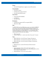
Audio
The SBC35-CC405 Intel
®
Atom E3800 family processor uses the Realtek ALC888S-VD
codec controller that provides both Digital and Analog channels. The controller has
three jack detection pins and a built-in beep generator. The SBC35-CC405 supports the
following audio interfaces: one digital (Display Port 1.1), two analog (Stereo Audio,
Line-In/Line-Out/Microphone), and one HD Audio (7.1 Surround). The Display Port 1.1
interface located at J15 also delivers video capability.
• HD Audio supported
• Interfaces: Display Port 1.1, Line Out, Line In, Mic to 3.5 mm, and 7.1 Surround
Power
• SBC35-CC405-3815: +10 to 50 V DC input (7 W typical, 9 W maximum)
• SBC35-CC405-3827: +10 to 50 V DC input (7.5 W typical, 10 W maximum)
• SBC35-CC405-3845: +10 to 50 V DC input (8.75 W typical, 12 W maximum)
Additional Features
• Watchdog timer from 1 second to 255 minutes (15,300 seconds) reset
Temperature
• Operating temperature: Fanless -40 °C to +85 °C (-40 °F to +185 °F);
SBC35-CC405-3845 requires a minimum airflow of 200 LFPM above 80 °C (176 °F)
if input voltage (V
CC
) is above 24 V DC.
• Storage temperature: -50 °C to +95 °C (-58 °F to +203 °F)

SBC35-CC405/Specifications
v1.0 www.winsystems.com Page 4
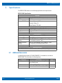
5. Specifications
The SBC35-CC405 adheres to the following specifications and requirements.
5.1 Additional Accessories
A standoff kit part number, KIT-IO60-STANDOFF-2, is included for use with the
SBC35-CC405. The kit contains the following items:
SBC35-CC405 Specifications
Electrical
V
CC
10 to 50 V DC ±5%, 15 Watts (maximum)
MTBF 14.5 Years
Battery: CR-2032 Chemical System: Li/MnO
2
Nominal Voltage: 3 V
Rated Capacity: 225 mAh
Mechanical
Dimensions 4 x 6.125 x 2.3 inches (102 x 165 x 58 mm)
Weight 1.40 lbs. (635 g) with heat sink
PCB thickness 0.078 inch
Environmental
Temperature -40 °C to +85 °C (-40 °F to +185 °F)
Humidity (RH) 5% to 95% non-condensing
Mechanical Shock
Testing
MIL-STD-202G, Method 213B, Condition A 50g half-sine,
11 ms duration per axis, 3 axis
Random Vibration
Testing
MIL-STD-202G, Method 214A, Condition D .1g/Hz
(11.95g rms), 20 minutes per axis, 3 axis
RoHS Compliant Yes
Operating Systems
Runs 32/64-bit Windows, Linux, and other x86-compatible operating systems.
Component Description Qty
Standoff Aluminum, 5 mm HEX,12 mm Long, 3.5 mm
thread, Male/Female
2
Hex Nut Zinc Finish, M3-0.5 DIN 2
Screw Stainless Steel, M3 x 0.5 mm x 6 mm PPH 2

SBC35-CC405/Setup
v1.0 www.winsystems.com Page 5
6. Setup
Use the information in Section 7 to help locate and identify the connectors outlined in
the following steps.
6.1 Installation and Connections
1. Connect a compatible monitor to the VGA output at J21, the Display port at J15, or
the LVDS and Backlight connector at J12, depending on your preference and
capabilities.
NOTE If you are using a flat panel display, make sure the jumper for Backlight Power at JP7 is
installed as required. See “Backlight Power (JP7)” on page 28 for specific requirements.
NOTE If you are using a flat panel display (connector J12), configure the panel orientation,
LVDS configuration, and bits per pixel to your preferences/requirements. For more
information, see “Panel Orientation (JP6)” on page 28; “LVDS Configuration (JP5)” on
page 27; and “Bits Per Pixel (JP4)” on page 27.
2. Connect a USB keyboard to any one of the four USB ports at J11 or J13.
3. Plug in the boot media of your preference. The options are:
– CFAST (J103 – on the back of the board)
– MSATA (J9)
– External SATA (J3)
– USB (J11 or J13)
– Ethernet (LAN boot – requires special CMOS settings)
4. Set the jumper at JP3 (Battery Select) for the type of battery backup to be used
(optional).
– Internal battery backup (Default) (jumper pins 2 & 3)
– No battery backup (no jumper installed)
– Optional external battery backup (jumper pins 1 & 2)
5. If using an external battery backup, connect the battery to J7.
6. Connect an Ethernet cable to either of the ports at J11 or J13.
6.2 Power up
Plug in a compatible +10 to +50 V DC power source at J5. The first time power is
applied, the SBC35-CC405 will boot automatically, bypassing the power button (SW1).
After initial startup, briefly press the power button to turn the SBC35-CC405 on and off.

SBC35-CC405/Configuration
v1.0 www.winsystems.com Page 6
7. Configuration
This section describes the SBC35-CC405 components and configuration.
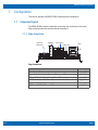
7.1 Component Layout
The SBC35-CC405 provides components on the edge, top, and bottom of the board.
Edge connections provide common external connections.
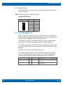
7.1.1 Edge Connections
Edge Connections:
Connection Reference
Power Input (J5) page 15
Stereo Audio: Line-In, Line-Out, and Microphone (J6) page 16
Ethernet (Top Half of Connectors J11 and J13) page 19
USB Channels 1 and 3 (J11) and Channels 2 and 4 (J13) page 21
Display Port 1.1 (J15) page 22
COM 1 and COM 2 (J19A and J19B) page 24
10-50 VDC
Power Input
Audio/Mic Ethernet Ports
COM 1
Display Port
COM 2

SBC35-CC405/Configuration
v1.0 www.winsystems.com Page 7
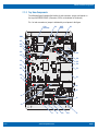
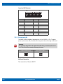
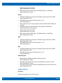
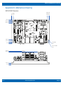
7.1.2 Top View Components
The following figure illustrates the location of each connector, jumper, and switch on
the top of the SBC35-CC405. (Connector J103 is on the bottom of the board.)
Pin 1 of each connector or jumper is indicated by a red square in the figure.
J21BAT1
BAT2
J103
(beneath)
J16
J20
JP8
J4
SW2
JP7
JP6
JP5
J14
JP4
J12
JP3
JP2
J10
J7
J8
J9
J1 J3 JP9 SP1 J2
J19
J15
J13
J11
J6
J5

SBC35-CC405/Configuration
v1.0 www.winsystems.com Page 8
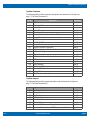
Top View Connectors
The following table provides connector descriptions and references for the figure on
page 7 (“Top View Components”).
Top View Jumpers
The following table provides jumper descriptions and references for the figure on
page 7 (“Top View Components”).
Item Description Reference
J1 SATA Power page 12
J2 HD Audio 7.1 Surround page 13
J3 Serial ATA page 14
J4 System Management page 14
J5 Power Input page 15
J6 Stereo Audio: Line-In, Line-Out, and Microphone page 16
J7 External Battery Connector page 16
J8 MiniPCIe page 17
J9 MiniPCIe/MSATA page 17
J10 External Fan Connector page 19
J11 Ethernet (top half of connector) page 19
J11 USB Channels 1 and 3 (bottom half of connector) page 20
J12 LVDS and Backlight page 21
J13 Ethernet (top half of connector) page 19
J13 USB Channels 2 and 4 (bottom half of connector) page 20
J14 USB Touchscreen page 21
J15 Display Port 1.1 page 22
J16 IO60 Expansion page 23
J19 COM 1 and COM 2 page 24
J20 Ethernet GPIO Controller page 24
J21 Analog VGA page 25
J103 CFAST (bottom of board) page 25
Item Description Reference
JP2 Fan Voltage Output page 26
JP3 Battery Select page 27
JP4 Bits Per Pixel page 27
JP5 LVDS Configuration page 27
JP6 Panel Orientation page 28
JP7 Backlight Power page 28
JP8 Ethernet GPIO Reference Voltage Selection page 29
JP9 Basic Input/Output System (BIOS) Programming Defaults page 29

SBC35-CC405/Configuration
v1.0 www.winsystems.com Page 9
Top View Switches
The following table provides switch descriptions and references for the figure on page 7
(“Top View Components”).
BAT1/BAT2
The SBC35-CC405 uses a single CR-2032 or CR-2025 battery. The nominal voltage of
either battery is 3.0 V. This battery, or alternatively an external battery connected to the
SBC35-CC405 board, provides standby power for the real-time clock and optional GPS.
See “Battery Select (JP3)” on page 27 and “External Battery Connector (J7) (Optional)”
on page 16 for more information.
7.2 Power
The SBC35-CC405 draws power through the J5 connector (see “Power Input (J5)” on
page 15). The main supply to the board is +10-50 V DC.
7.3 Watchdog Timer
The SBC35-CC405 features an advanced watchdog timer (WDT) that can be used to
guard against software lockups. The timer is programmable from 1 second to 255
minutes.
NOTE Use a long timeout if the watchdog is enabled when trying to boot any operating
system.
The watchdog can be enabled, disabled, or reset by writing the appropriate values to the
configuration registers. The WDT is part of the embedded controller, which uses the
following command sequence:
CMD Register: 0x66
Read Command: 0x80
Write Command: 0x81
Sync Command: 0x82
DATA Register: 0x62
Item Description Reference
SW1 Power Button page 29
SW2 Reset Button page 30

SBC35-CC405/Configuration
v1.0 www.winsystems.com Page 10
The watchdog timer initialization requires that the CMD register be cleared and then
configured to write the command, and then the data written. Example code for C and
Basic are provided following the tables.
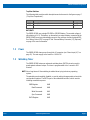
Watchdog Timer Control Register
Offset Address: 0x06, Attribute: R/W, Size: 8 bit
Bit Description
7 Reserved
6 WDT event reset
Software writes a 1 to this bit to clear the WDT event.
5:4 Watchdog Timer Output Modes.
00: Generating an internal reset and WDT pin is driven high until the unit
resets.
01: Driving WDT pin high until cleared by software.
3:2 Reserved.
1 Select WDT count mode.
0: Second Mode.
1: Minute Mode.
0 Disable / Enable the WDT function.
0: Disable
1: Enable
Watchdog Timer Control Register for Minutes
Offset Address: 0x07, Attribute: R/W, Size: 8 bit
Bit Description
7:0 Timer Counter Register (Minutes)
Watchdog timer time-out value in minutes (Default value = 0x00)
Watchdog Timer Control Register for Seconds
Offset Address: 0x08, Attribute: R/W, Size: 8 bit
Bit Description
7:0 Timer Counter Register (Seconds)
Watchdog timer time-out value in minutes (Default value = 0x00)

SBC35-CC405/Configuration
v1.0 www.winsystems.com Page 11
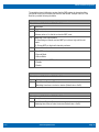
7.3.1 Example code (C WDT)
The following code example for the watchdog timer is written in C:
Offset = [Register]
Value = [Data]
VOID Write_EC_SRAM(UINT8 Offset,UINT8 Value){
UINT8 tmp,count;
count=100;
do{
IoWrite8(0x66,0x82);
pBS->Stall(1000); //uint=1us
tmp=IoRead8(0x62);
count--;
}while (((tmp&0x10)==0) & (count>0));
IoWrite8(0x66,0x81);
Delay1MS(1);
IoWrite8(0x62,Offset);
Delay1MS(1);
IoWrite8(0x62,Value);
}
int Read_EC_SRAM(UINT8 Offset){
UINT8 tmp,count;
count=100;
do{
IoWrite8(0x66,0x82);
pBS->Stall(1000); //uint=1us
tmp=IoRead8(0x62);
count--;
}while (((tmp&0x10)==0) & (count>0));
IoWrite8(0x66,0x80);
Delay1MS(1);
IoWrite8(0x62,Offset);
Delay1MS(1);
IoRead8(0x62,Value);
return Value;
}

SBC35-CC405/Configuration
v1.0 www.winsystems.com Page 12
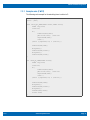
7.3.2 Example Code: Basic
The following code example for the watchdog timer is written in Basic:
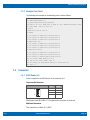
7.4 Connectors
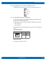
7.4.1 SATA Power (J1)
Power is supplied to the SATA device via the connector at J1.
Layout and Pin Reference:
WinSystems cable CBL-PWR-117-12 simplifies this connection to the board.
Additional Information
This connection is a Molex 22-11-2042.
3 PRINT TIME$;" ";DATE$
4 O=VAL(RIGHT$(TIME$,2))
5 C=&H66:D=&H62:W=&H81:R=&H80:TRON
6 P=INP(C): IF (P=0) THEN GOTO 10 ELSE IF (P=1) THEN PRINT INP(D) ELSE
IF (P=8) THEN OUT D,6: GOTO 200
7 GOTO 6
9 REM write reg 08 with 05
10 TROFF
11 IF (INP(C)=0) THEN OUT C,W ELSE GOTO 11
20 IF (INP(C)=8) THEN OUT D,8 ELSE GOTO 20
30 IF (INP(C)=0) THEN OUT D,O ELSE GOTO 30
39 REM enable dog
40 IF (INP(C)=0) THEN OUT C,W ELSE GOTO 40
50 IF (INP(C)=8) THEN OUT D,6 ELSE GOTO 50
60 IF (INP(C)=0) THEN OUT D,1 ELSE GOTO 60
69 REM read counter
70 IF (INP(C)=0) THEN OUT C,R ELSE GOTO 70
80 IF (INP(C)=8) THEN OUT D,8 ELSE GOTO 80
90 IF (INP(C)=1) THEN T=INP(D) ELSE GOTO 90
100 IF (T<>T2) THEN PRINT T;: T2=T
110 FOR X=1 TO 10000: NEXT: GOTO 70
200 IF (INP(C)=1) THEN PRINT INP(D);"*" ELSE GOTO 200
210 GOTO 10
Pin Name
1 +5 V
2GND
3GND
4 +12 V
1
4

SBC35-CC405/Configuration
v1.0 www.winsystems.com Page 13
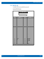
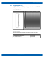
7.4.2 HD Audio 7.1 Surround (J2)
The HD Audio connection delivers audio output depending on the cable used:
• WinSystems Cable CBL-AUDIO7-102-12: delivers 7.1 (surround sound) audio
• WinSystems Cable CBL-AUDIO5-102-12: delivers 5.1 audio
• WinSystems Cable CBL-AUDIO3-102-12: delivers stereo audio
Layout and Pin Reference:
Additional Information
This connection is a Molex 501931-3070.
Pin Name Pin Name
1 OUT-R 2 MIC1-REAR-R
3 OUT-L 4 MIC1-REAR-L
5 ADGND 6 ADGND
7 SUR-R 8 MIC2-REAR-R
9 SUR-L 10 MIC2-REAR-L
11 ADGND 12 ADGND
13 CENTER 14 LINE-R
15 LFE 16 LINE-L
17 ADGND 18 ADGND
19 SIDE-R 20 CD-R
21 SIDE-L 22 CD-L
23 ADGND 24 CDGND
25 HEADPHONE-R 26 ADGND
27 HEADPHONE-L 28 ADGND
29 ADGND 30 ADGND
2
1
30
29

SBC35-CC405/Configuration
v1.0 www.winsystems.com Page 14
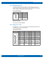
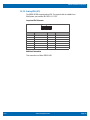
7.4.3 Serial ATA (J3)
The bootable SATA (2.0) interface is located at J3. WinSystems offers CBL-SATA-701-
20 for this connector.
NOTE J3 cannot be used when J9 mSATA is present.
Layout and Pin Reference:
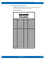
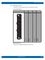
7.4.4 System Management (J4)
System management functions and events use J4 for connectivity from the SBC and
CPU to the rest of the system. This enables the SBC and System to properly notify and
respond to Power, Sleep/Wake, Thermal, and Security events.
The SPI and I2C interfaces on this connector can also be used for additional system
connectivity such as enclosure management, SMBus, or PMBus connectivity.
Pin 2 (LID#) indicates whether the system is on/off or opened/closed, and can be used
for an intruder alert. If this bit is set, you can wire it to your system to initiate a system
shutdown.
Optionally, you can use J4 to initiate sleep mode via Pin 3.
Pin 4 indicates thermal trip status. You can be notified of a thermal trip, and action
(such as a system shutdown) is taken in response to the system overheating. More
information regarding thermal protection signaling is provided in the table below.
Pin Name
1GND
2RX1+
3RX1-
4GND
5TX1-
6TX1+
7GND
7
1
Thermal Protection Pin Power Rail Description
THRM# 6 3.3 V / 3.3 V Input from off-Module temp sensor indicating an over-
temp situation.
THRMTRIP# 4 3.3 V / 3.3 V Active low output indicating that the CPU has entered
thermal shutdown.

SBC35-CC405/Configuration
v1.0 www.winsystems.com Page 15
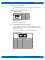
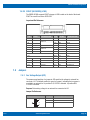
Layout and Pin Reference:
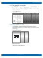
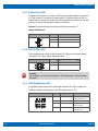
7.4.5 Power Input (J5)
The SBC35-CC405 is capable of operating from +10 to +50 VDC (+/-5%). The green
power input connector (J5) is located next to the power button on the edge of the board.
Additional Information
This connection is a Phoenix 1803277.
Pin Name Pin Name
1PWRBTN 2 LID#
3 SLEEP 4 THRMTRIP#
5
I
2
C_CLK
6THRM#
7
I
2
C_DAT
8WAKE
9 SYS_RESET 10 NC
11 SPI_PWR 12 VCC_5V
13 SPI_MISO 14 VCC_3.3V
15 SPI_CLK 16 GND
17 SPI_MOSI 18 GND
19 SPI_CS5 20 GND
1
2
19
20
Warning
Do not reverse the positive and negative terminals when you connect power to the
unit. This will void the warranty and damage the board.
Power Connector (J5) Power Button (SW1)
+-

SBC35-CC405/Configuration
v1.0 www.winsystems.com Page 16
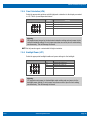
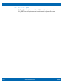
7.4.6 Stereo Audio: Line-In, Line-Out, and Microphone (J6)
The SBC35-CC405 uses 3.5 mm stereo line-in, line-out, and microphone jacks at J6.
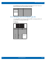
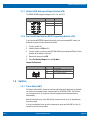
7.4.7 External Battery Connector (J7) (Optional)
An external battery connected to the SBC35-CC405 board provides standby power for
the real-time clock, CMOS, and optional GPS.
Extended temperature lithium batteries are available from WinSystems, part numbers:
• BAT-LTC-E-36-16-1
• BAT-LTC-E-36-27-1
The on-board battery is the default configuration on this product. The external battery is
optional.
Layout and Pin Reference:
Additional Information
This connection is a Molex 22-11-2032.
Line In
Line Out
Mic In
Pin Name
1GND
2 VBAT
3GND
1
2
3
Page is loading ...
Page is loading ...
Page is loading ...
Page is loading ...
Page is loading ...
Page is loading ...
Page is loading ...
Page is loading ...
Page is loading ...
Page is loading ...
Page is loading ...
Page is loading ...
Page is loading ...
Page is loading ...
Page is loading ...
Page is loading ...
Page is loading ...
Page is loading ...
Page is loading ...
Page is loading ...
Page is loading ...
Page is loading ...
Page is loading ...
Page is loading ...
Page is loading ...
Page is loading ...
Page is loading ...
Page is loading ...
Page is loading ...
Page is loading ...
Page is loading ...
Page is loading ...
Page is loading ...
Page is loading ...
Page is loading ...
Page is loading ...
Page is loading ...
-
 1
1
-
 2
2
-
 3
3
-
 4
4
-
 5
5
-
 6
6
-
 7
7
-
 8
8
-
 9
9
-
 10
10
-
 11
11
-
 12
12
-
 13
13
-
 14
14
-
 15
15
-
 16
16
-
 17
17
-
 18
18
-
 19
19
-
 20
20
-
 21
21
-
 22
22
-
 23
23
-
 24
24
-
 25
25
-
 26
26
-
 27
27
-
 28
28
-
 29
29
-
 30
30
-
 31
31
-
 32
32
-
 33
33
-
 34
34
-
 35
35
-
 36
36
-
 37
37
-
 38
38
-
 39
39
-
 40
40
-
 41
41
-
 42
42
-
 43
43
-
 44
44
-
 45
45
-
 46
46
-
 47
47
-
 48
48
-
 49
49
-
 50
50
-
 51
51
-
 52
52
-
 53
53
-
 54
54
-
 55
55
-
 56
56
-
 57
57


WinSystems SBC35-CC405-3845 User manual
- Category
- Motherboards
- Type
- User manual
- This manual is also suitable for
Ask a question and I''ll find the answer in the document
Finding information in a document is now easier with AI
Related papers
-
WinSystems IO60-GNSS User manual
-
WinSystems IO60-M410 User manual
-
-
-
WinSystems IO60-DIO48 User manual
-
-
-
-
-
WinSystems SBC35-427 User manual
Other documents
-
DeLOCK 95225 Datasheet
-
Approx APPPCI2P3 Datasheet
-
DeLOCK 95228 Datasheet
-
Korenix JetWave 1402 User manual
-
AVLink DPS-2 Owner's manual
-
-
PEAK PCIe-miniPCIe User manual
-
Eurotech CPU-163-15 Owner's manual
-
-
 PEAK-System PCIe-miniPCIe Low-Profile-Adapter Operating instructions
