Honeywell CT51 Owner's manual
- Category
- Thermostats
- Type
- Owner's manual
This manual is also suitable for

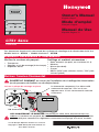
CT51 Series
Thermostat
Getting started
Before you begin, make sure you have:
• No. 2 Phillips & small pocket screwdrivers
• Hammer
• Level (optional)
• Pencil
• Drill and bit (3/16” for drywall, 7/32” for plaster)
® U.S. Registered Trademark. Patents pending.
Copyright © 2006 Honeywell International Inc.
All rights reserved.
Owner’s Manual
English: Page 1
Mode d’emploi
Français: Page 6
Manual de Uso
Español: Página 11
Check package contents:
• Thermostat
• Wall anchors & screws (2 each)
• Wire labels
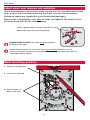
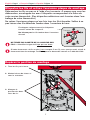
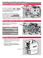
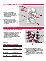
Remove your old thermostat
TURN OFF POWER at heating/cooling system (or fuse/circuit-breaker panel).
Remove cover and thermostat, but leave wallplate with wires attached.
Old thermostat
Leave wallplate in place Is there a sealed tube containing mercury?
If so, see mercury notice below.
Cover
MERCURY NOTICE: If your old thermostat contains mercury, contact your local waste
management authority for proper disposal instructions.
These models provide control of 24 Vac heating & cooling systems:
Vertical Mount: CT51N • Horizontal Mount: CT55N

CT51 Series
2
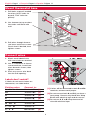
Label wires and remove old wallplate
Use a screwdriver to disconnect wires one by one. As you disconnect each
wire, wrap it with the label matching the letter on your old thermostat.
(Adhesive labels are supplied in your thermostat package.)
Remove the old wallplate only after all wires are labeled. Be careful not to
let loose wires fall into the wall opening.
Wrap supplied labels securely around each wire
Do not let wires fall into wall opening!
IGNORE WIRE COLORS: Use only letter designations
to identify wire types.
If your old thermostat has 7 or more wires (not counting terminals C or C1),
you may have purchased the wrong replacement thermostat. Stop now and call
1-800-468-1502 for advice.
Mark mounting position
1 Pull wires through base.
2 Level base if desired.
3 Mark positions of
both screw holes.

English: Page 1 • Français: Page 6 • Español: Página 11
3
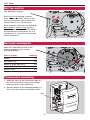
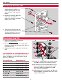
Connect wires
1 Match each labeled wire
with same letter on terminal.
2 Use a screwdriver to loosen
screw terminals, insert bare
wires beneath screws, then
tighten screws.
3 Push any excess wire back
into the wall opening.
Labels don’t match?
If labels do not match letters on
thermostat, see table below.
Mount thermostat base
1 Drill holes at pencil-marked
locations (3/16” holes for
drywall, 7/32” holes for
plaster).
[1] If wires will be connected to both R and Rc
terminals, remove metal jumper.
[2] Do not connect both O and B if you have a
heat pump. Connect only the O wire. Wrap
B wire with electrical tape and do not use.
[3] Do not use C, X or B. Wrap bare end of
wire with electrical tape.
Existing wires Connect to:
R • RH • 4 • V Terminal “R” [1]
Rc Terminal “Rc” [1]
O Terminal “O” [2]
B Terminal “B” [2]
G • F Terminal “G”
W • W1 • H Terminal “W”
Y • Y1 • M Terminal “Y”
C • X • B Do not use [3]
2 Use hammer to tap anchors
into holes until flush with
wall.
3 Pull wires through thermo-
stat base and insert screws.
Check level if desired, then
tighten screws.

CT51 Series
4
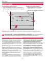
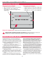
Set fan switch
Fan operation settings:
F: For gas or oil heating systems,
leave the fan operation switch in this
factory-set position (for systems that
control the fan in a call for heat.)
E: Change the switch to this setting for
heat pump
or electric heat
systems.
(This setting is for systems that allow
the thermostat to control the fan in a
call for heat, if a fan wire is connected
to the G terminal.)
Set heat anticipator
Move the adjustment arrow to the
proper setting for your system
(see table below).
Your system Setting
Steam 1.2
Hot water heat 0.8
Warm air (high efficiency) 0.8
Warm air (standard) 0.4
Electric heat 0.3
Thermostat mounting
1 Align the slots on the cover with tabs on
the sides of the base, then push gently
until the cover snaps into place.
2 Restore power at the heating/cooling sys-
tem, or at the fuse/circuit breaker panel.
Tab

English: Page 1 • Français: Page 6 • Español: Página 11
5
1-year limited warranty
Honeywell warrants this product to be free from defects in
the workmanship or materials, under normal use and service,
for a period of one (1) year from the date of purchase by the
consumer. If at any time during the warranty period the prod-
uct is determined to be defective or malfunctions, Honeywell
shall repair or replace it (at Honeywell's option).
If the product is defective,
(i) return it, with a bill of sale or other dated proof of pur-
chase, to the place from which you purchased it; or
(ii) call Honeywell Customer Care at 1-800-468-1502.
Customer Care will make the determination whether the
product should be returned to the following address:
Honeywell Return Goods, Dock 4 MN10-3860, 1885 Douglas
Dr.N., Golden Valley, MN 55422, or whether a replacement
product can be sent to you.
This warranty does not cover removal or reinstallation
costs. This warranty shall not apply if it is shown by
Honeywell that the defect or malfunction was caused by
damage which occurred while the product was in the
possession of a consumer.
Honeywell's sole responsibility shall be to repair or
replace the product within the terms stated above. HONEY-
WELL SHALL NOT BE LIABLE FOR ANY LOSS OR DAMAGE
OF ANY KIND, INCLUDING ANY INCIDENTAL OR CONSE-
QUENTIAL DAMAGES RESULTING, DIRECTLY OR
INDIRECTLY, FROM ANY BREACH OF ANY WARRANTY,
EXPRESS OR IMPLIED, OR ANY OTHER FAILURE OF THIS
PRODUCT. Some states do not allow the exclusion or
limitation of incidental or consequential damages, so this
limitation may not apply to you.
THIS WARRANTY IS THE ONLY EXPRESS WARRANTY
HONEYWELL MAKES ON THIS PRODUCT. THE DURATION
OF ANY IMPLIED WARRANTIES, INCLUDING THE WAR-
RANTIES OF MERCHANTABILITY AND FITNESS FOR A
PARTICULAR PURPOSE, IS HEREBY LIMITED TO THE ONE-
YEAR DURATION OF THIS WARRANTY. Some states do not
allow limitations on how long an implied warranty lasts, so
the above limitation may not apply to you.
This warranty gives you specific legal rights, and you
may have other rights which vary from state to state.
If you have warranty questions, please write Honeywell
Customer Relations, 1985 Douglas Dr, Golden Valley, MN
55422 or call 1-800-468-1502. In Canada, write Retail
Products ON15-02H, Honeywell Limited/Honeywell Limitée,
35 Dynamic Drive, Scarborough, Ontario M1V4Z9.
Operation
System switch
• Cool: Controls the cooling system.
• Heat: Controls the heating system.
• Off: All systems are off.
Fan switch
• On: Fan runs continuously.
• Auto: Fan runs only when heating or
cooling system is on.
Temperature setting: Adjust to set desired indoor temperature.
CAUTION: EQUIPMENT DAMAGE HAZARD. Do not operate cooling system when
outdoor temperature is below 50°F (10°C).
Page is loading ...
Page is loading ...
Page is loading ...
Page is loading ...
Page is loading ...
Page is loading ...
Page is loading ...
Page is loading ...
Page is loading ...
Page is loading ...

Need Help?
For assistance with this product please visit http://yourhome.honeywell.com
or call Honeywell Customer Care toll-free at 1-800-468-1502
Honeywell International Inc.
1985 Douglas Drive North
Golden Valley, MN 55422
http://yourhome.honeywell.com
Automation and Control Solutions
® U.S. Registered Trademark.
© 2006 Honeywell International Inc.
Patents pending. All rights reserved.
Printed in China.
69-1946EFS • 05-2006
Honeywell Limited-Honeywell Limitée
35 Dynamic Drive
Scarborough, Ontario M1V 4Z9
Vous faut-il de l’aide ?
Pour obtenir de l’assistance concernant ce produit, visitez http://yourhome.honeywell.com
ou appelez gratuitement l’assistance client d’Honeywell au 1-800-468-1502
¿Necesita ayuda?
Consulte sobre este producto en http://yourhome.honeywell.com
o llamando sin cargo a atención al cliente de Honeywell 1-800-468-1502
-
 1
1
-
 2
2
-
 3
3
-
 4
4
-
 5
5
-
 6
6
-
 7
7
-
 8
8
-
 9
9
-
 10
10
-
 11
11
-
 12
12
-
 13
13
-
 14
14
-
 15
15
-
 16
16


Honeywell CT51 Owner's manual
- Category
- Thermostats
- Type
- Owner's manual
- This manual is also suitable for
Ask a question and I''ll find the answer in the document
Finding information in a document is now easier with AI
in other languages
- français: Honeywell CT51 Le manuel du propriétaire
- español: Honeywell CT51 El manual del propietario
Related papers
-
Honeywell RTH9580WF1005/W1 User manual
-
-
Honeywell CT50 Owner's manual
-
-
-
-
Honeywell CT87N User manual
-
Honeywell Round T87K User manual
-
Honeywell CT31A1003/U1 User manual
-
Other documents
-
UPM THM101B Owner's manual
-
-
 Lutron Electronics 33-00155EFS Installation guide
-
ClimateMaster ATA11H01, ATA21H01 and ATA32H01 User guide
-
 Honeywell Home RTHL221B1008/K1 Installation guide
-
White Rodgers 1E56N-444 User manual
-
 Honeywell Home CG511A User manual
-
-
Emerson 1E50N-301 User manual
-
White Rodgers White-Rodgers 1E30N-910 Mercury Free Mechanical Thermostat User manual


