White Rodgers White-Rodgers 1E30N-910 Mercury Free Mechanical Thermostat User manual

Type
User manual
Do not use on circuits exceeding speci ed voltage. Higher voltage will
damage control and could cause shock or fi re hazard.
Do not short out terminals on gas valve or primary control to test. Short or
incorrect wiring will damage thermostat and could cause personal injury
and/or property damage.
Thermostat installation and all components of the system shall conform
to Class II circuits per the NEC code.
YOUR THERMOSTAT REPLACES
System Models
Standard Heat Only Systems
1E30N-910
1E50N-301
Electric Furnace
Heat Pump (No Aux or Emergency Heat)
Gas or Oil Heat
Millivolt Heat Only Systems
1PREPARATIONS
Assemble tools required: power drill, fl at blade screwdriver, wire cutter/stripper, level.
Failure to follow and read all instructions carefully before installing or op-
erating this control could cause personal injury and/or property damage.
2THERMOSTAT FEATURES
Captive
screws
Mounting
Screw
Mounting
Screw
COVER
THERMOSTAT
BASE
WALLPLATE
SWITCHING
SUBBASE
S
Y
S
T
E
M
O
F
F
H
E
A
T
G
W
RH
Mounting
Screw
50
60 70 80
90
50 60 70 80 90
4
Figure 1. Thermostat with subbase or wallplate
To prevent electrical shock and/or equipment damage, disconnect electrical
power to the system at the main fuse or circuit breaker until installation is
complete.
CAUTION
!
Before removing wires from old thermostat’s switching subbase, label each wire with
the terminal designation it was removed from.
1. Remove Old Thermostat: A standard thermostat consists of three basic parts:
a. The cover, which may be either a snap-on or hinge type.
b. The base, which is removed by loosening all captive screws.
c. The switching subbase, which is removed by unscrewing the mounting
screws that hold it on the wall or adaptor plate.
Make a note here of the anticipator setting on the old thermostat
for future reference and use in step 5.
The heat anticipator pointer, if adjustable, will be set at one of a series of numbers
representing the current rating of the primary control in your furnace. The number will
be one of the following: .2, .4, .8, etc. or 0.2, 0.4, 0.8, etc.
3
3REMOVING OLD THERMOSTAT (cont’d)
If no heat anticipator/indication is showing, do not be concerned; move on to the
next step.
ATTENTION! This product does not contain mercury. However, this product may
replace a unit which contains mercury.
Do not open mercury cells. If a cell becomes damaged, do not touch any spilled
mercury. Wearing non-absorbent gloves, take up the spilled mercury and place into
a container which can be sealed. If a cell becomes damaged, the unit should be
discarded.
Mercury must not be discarded in household trash. When the unit this product is
replacing is to be discarded, place in a suitable container. Refer to www.white-
rodgers.com for location to send product containing mercury.
4MOUNTING AND WIRING
WARNING
!
A. Remove base from subbase or wallplate: Loosen the screws on the base and
remove.
B. Mount switching subbase or wallplate: Use the screws provided to mount the
subbase or wallplate to wall (see Fig. 1).
C. Attach wires to appropriate terminals: Two wire systems (Heat Only). Attach
one wire to RH and one to wire W.
D. Mount Thermostat Base: Gently push excess wire back into the wall opening
and plug hole with a fi re-resistant material, such as fi berglass insulation to pre-
vent drafts from affecting thermostat operation. Mount the thermostat base to
the subbase or wallplate using the three captive screws on the thermostat base.
(See Fig. 1) Tighten the screws securely. Proceed to Step #5.
TERMINAL CROSS REFERENCE CHART
New Thermostat Other Manufacturers’
Terminal Designation Terminal Designation
R H 4 R H M R 5 R
W W W H 4 W
5
Set anticipator to match the setting of your old thermostat you noted in Step 3, or, the
anticipator should be set to match the current rating stamped on your main heating
control. The heat anticipator is adjustable from 0.15 to 1.2 amps. Adjust the anticipa-
tor by rotating the contact arm (see fi g. 2). The anticipator setting is indicated by the
numbers on the base that the pointer points to. If you are unsure where to set the
anticipator contact the heater manufacturer for a recommended setting.
Move the pointer counterclockwise to
lengthen heating system cycles; move
clockwise to shorten heating cycles.
Adjustments should not be greater than
1/2 marking at a time.
For millivolt operation, rotate contact arm to
Millivolt Link.
Snap on Cover: Carefully align the cover
with the base and snap the cover onto
the base.
Rotate contact arm
to adjust heat anticipator
Arrow points to the
current rating of
the primary control
Millivolt Link
REMOVING OLD THERMOSTAT
Take care when securing and routing wires so they do not short to adjacent
terminals or rear of thermostat. Personal injury and/or property damage may
occur.
CAUTION
!
SET HEAT ANTICIPATOR
Figure 2. Anticipator adjustment
Installation Instructions for:
Vertical
Snap Action
1E30N-910
1E50N-301
www.white-rodgers.com PART NO. 37-6844B
Replaces 37-6844A
0920
Symptom Possible Cause Corrective Action
No Heat/ No Fan 1. Blown fuse or tripped circuit breaker. Replace fuse or reset breaker.
(common problems) 2. Furnace power switch to OFF. Turn switch to ON.
3. Furnace blower compartment door or Replace door panel in proper position to engage
panel loose or not properly installed. safety interlock or door switch.
No Heat 1. Pilot light not lit. Re-light pilot.
2. Broken or melted anticipator wire. Excessive current or dead short in system. Have a qualifi ed service person check the system
3. Loose connection to thermostat before replacing thermostat.
or system. Verify thermostat and system wires are securely attached.
4. Thermostat or heating system requires Your furnace manufacturer or service person can describe how to test the heating system to
replacement or service. verify it is operating correctly. If the heating system is capable of operation and the no heat
5. System Switch not set to Heat. condition persists, replace the thermostat.
Set System Switch to Heat and raise temp above room temp.
Intermittent Heat 1. Furnace Lock-Out Condition Many furnaces have safety devices that shut the system down when a lock-out condition occurs.
If the heat works intermittently contact the furnace manufacturer or local service person for
assistance.
Heat or Fan Runs 1. Possible short in wiring. Check each wire connection to the thermostat to verify it is neatly looped under the terminals.
Constantly. 2. Possible short in thermostat. No extra wire should stick out from under the terminals.
3. Possible short in heat/cool/fan system.
Furnace Cycles Too Fast See Step 5, Adjusting the Anticipator. The anticipation setting is the only adjustment that effects the heating cycle rate. If an accept-
or Too Slow Narrow or able cycle rate is not achieved using the anticipator contact a local service person for addi-
wide temperature swing tional suggestions. The location of the thermostat, size of the Heat/Cool System and current
draw can infl uence the cycle rate.
Thermostat Setting and 1. Thermostat thermometer setting The thermometer can be adjusted by using a standard slotted screwdriver. Turn the thermom-
Thermostat Thermometer requires adjustment. eter pointer screw located inside the front cover to change the setting. For calibrating the
Disagree 2. Thermostat setting lever requires setting lever contact a local heating and cooling service person.
calibration.
Adjusting Thermometer 1. Thermostat thermometer disagrees The thermometer on the thermostat is accurately calibrated at our factory but you can adjust it
with other room thermometers. by using a standard slotted screwdriver. Turn the thermometer pointer screw located inside
the front cover to change the setting.
7
6
8
NEW THERMOSTAT OPERATION
This thermostat is easy to operate. After power is turned on, use the system switch to
select heating, or to turn the heating system off.
SPECIFICATIONS
ELECTRICAL DATA
Switch Rating...................................... 24 VAC (30 VAC max.)
Heating.................................................. 0.15 to 1.2 Amps
Anticipator Rating:
Heating.................................................. Adjustable from 0.15 to 1.2 Amps
THERMAL DATA:
Temperature Range............................. 50°F to 90°F (10°C to 32°C)
Operating Humidity Range................. 0 – 90% noncondensing
TROUBLESHOOTING
WR
Heat
Anticipator
(adjustable)
Heating
System
24 VAC 120 VAC
Hot
Neutral
THERMOSTAT
SYSTEM
Figure 3. Typical wiring for single transformer heating system
www.white-rod
g
ers.com
White-Rodgers is a division
of Emerson Electric Co.
The Emerson logo is a
trademark and service mark
of Emerson Electric Co.
HOMEOWNER HELP LINE: 1-800-284-2925
7
6
8
FUNCIONAMIENTO DEL NUEVO TERMOSTATO
Este termostato es fácil de usar. Una vez encendida la alimentación, utilice el interruptor del sistema
para seleccionar calefacción, o para apagar el sistema de calefacción.
ESPECIFICACIONES
DATOS ELÉCTRICOS
Características del interruptor...................................... 24 VCA (30 VCA máx.)
Calefacción........................................................................ 0.15 a 1.2 A
Características del anticipador:
Calefacción........................................................................ Ajustable de 0.15 a 1.2 A
DATOS TÉRMICOS:
Rango de temperatura de referencia........................... 50°F a 90°F (10°C a 32°C)
Rango de humedad operativa....................................... 0 a 90 % sin condensación
SOLUCIÓN DE PROBLEMAS
WR
Anticipador de calor
(ajustable)
Sistema
de calor
24 VCA 120 VCA
Vivo
Neutro
SISTEMA DE
TERMOSTATO
Figura 3. Diagrama de conexiones típico para sistema de calor de un solo transformador
Síntoma Causa posible Acción correctiva
El sistema no calienta/ 1. Se quemó el fusible o se disparó el disyuntor. Cambie el fusible o vuelva a activar el disyuntor.
No funciona el ventilador 2. El interruptor de alimentación del calefactor Coloque el interruptor en ON.
(problemas comunes) está en OFF.
3. La puerta o el panel del compartimento del soplador Vuelva a colocar el panel de la puerta en el lugar correcto para que se
del calefactor están sueltos o no están debidamente enganche con el interruptor de interbloqueo de seguridad o de la puerta.
instalados.
El sistema no calienta 1. La luz piloto no está encendida. Vuelva a encender el piloto.
2. Cable de anticipador roto o fundido. Corriente excesiva o cortocircuito total en el sistema. Pida a un técnico calicado que revise
el sistema antes de cambiar el termostato.
3. La conexión al termostato o al sistema está suelta. Verique que los cables del termostato y del sistema estén bien conectados.
4. El termostato o sistema de calefacción requiere El fabricante o técnico de su calefactor pueden explicarle cómo probar el sistema de calefacción
servicio técnico o debe cambiarse el termostato. para vericar si está funcionando correctamente. Si el sistema de calefacción funciona y persiste la
condición de no calor, cambie el termostato.
5. El interruptor System no está ajustado en Heat. Ajuste el interruptor System en Heat y suba la temperatura de referencia por encima de la
temperatura ambiente.
Calor intermitente 1. Condición de bloqueo de calefactor. Muchos calefactores tienen dispositivos de seguridad que se cierran cuando se produce una condición
de bloqueo. Si la calefacción funciona de manera intermitente, póngase en contacto con el fabricante
del calefactor o con el personal técnico local para solicitar ayuda.
El modo de calor o 1. Posible cortocircuito en los cables. Revise la conexión de cada cable al termostato para asegurarse de que esté debidamente enroscada
ventilador funciona 2. Posible cortocircuito en el termostato. debajo de las terminales. Los cables no deben sobresalir por debajo de las terminales.
de manera constante 3. Posible cortocircuito en el sistema de calor/frío/
ventilador.
Los ciclos del calefactor Vea el paso 5, Ajuste del anticipador. El ajuste de anticipación es el único ajuste que afecta la velocidad del ciclo de calefacción. Si no se
son demasiado cortos logra una velocidad de ciclo aceptable utilizando el anticipador, consulte a un técnico local. La
o demasiado largos ubicación del termostato, el tamaño del sistema de calor/frío y la toma de corriente pueden inuir en la
(oscilación reducida o velocidad del ciclo.
amplia de la temperatura)
El ajuste del termostato no 1. Es necesario ajustar el termómetro del termostato. El termómetro puede ajustarse utilizando un destornillador ranurado común. Gire el tornillo indicador
coincide con el termómetro 2. La palanca de ajuste del termostato requiere del termómetro ubicado dentro de la cubierta delantera para modicar el ajuste. Para calibrar la
calibración. palanca de ajuste, póngase en contacto con un técnico local especializado en sistemas de calefacción
y enfriamiento.
Ajuste del termómetro 1. El termómetro del termostato no coincide con El termómetro del termostato viene calibrado con precisión de fábrica pero puede ajustarlo utilizando
otros termómetros de la habitación. un destornillador ranurado común. Gire el tornillo indicador del termómetro dentro de la cubierta
delantera para modicar el ajuste.
www.white-rodgers.com
LÍNEA DE AYUDA PARA EL USUARIO: 1-800-284-2925
White-Rodgers es una división
de Emerson Electric Co.
El logotipo de Emerson es una
marca comercial y una marca de
servicio de Emerson Electric Co.
No utilizar en circuitos que excedan el voltaje especicado ya que los voltajes más altos
dañan el control y pueden causar riesgos de electrocución o incendio.
No cortocircuite las terminales de la válvula de gas ni del control principal para probar-
los. Un cortocircuito o una conexión incorrecta dañarán el termostato y podría causar
lesiones personales y/o daños materiales.
La instalación del termostato y de todos los componentes del sistema de control debe
ajustarse a las normas del código NEC para los circuitos Clase II.
Instrucciones de instalación para:
Acción rápida 1E30N-910,
vertical 1E50N-301
SU TERMOSTATO REEMPLAZA
Sistema Modelos
Sistemas de sólo calor estándar
Calefactor eléctrico 1E30N-910
Bomba de calor (sin calor auxiliar o de emergencia) 1E50N-301
Sistemas de calefacción de gas o aceite
Sistemas de sólo calor milivoltios
1
PREPARACIÓN
Reúna las herramientas requeridas: taladro eléctrico, destornillador de hoja plana, tenazas/desai-
slador, nivel.
El no leer y seguir con cuidado todas las instrucciones antes de instalar o utilizar este
control podría causar lesiones personales y/o daños materiales.
2
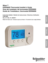
DETALLES DEL TERMOSTATO
To rnillos
cautivos
CUBIERTA
BASE DEL
TERMOSTATO
PLACA DE PARED
SUBBASE
DE CONMUTACIÓN
S
Y
S
T
E
M
O
F
F
H
E
A
T
G
W
RH
To rnillo
de montaje
50
60 70 80
90
50 60 70 80 90
4
To rnillo
de montaje
To rnillo
de montaje
Figura 1. Subbase y placa de pared del termostato
Para evitar descargas eléctricas y/o daños al equipo, desconecte la alimentación eléctri-
ca en la caja de fusibles o disyuntores principal hasta que haya finalizado la instalación
del sistema.
¡PRECAUCIÓN!
!
Antes de retirar los cables de la subbase de conmutación del termostato viejo, identique cada cable
con la designación de la terminal de la que lo desconectó.
1. Retire el termostato viejo: Un termostato estándar consta de tres partes básicas:
a. La cubierta, que puede ser tipo bisagra o de broche.
b. La base, que se retira aojando todos los tornillos cautivos.
c. La subbase de conmutación, que se retira desenroscando los tornillos de montaje que
la sujetan a la pared o a la placa adaptadora.
Tome nota aquí del ajuste del anticipador del termostato viejo para referencia
futura y para utilizarlo en el paso 5.
El indicador del anticipador de calor, si es ajustable, se ajustará en uno de una serie de números
que representan la corriente nominal del control principal de su calefactor. El número será uno de los
siguientes: .2, .4, .8, etc. o 0.2, 0.4, 0.8, etc.
3
3
CÓMO RETIRAR EL TERMOSTATO VIEJO (continuación)
Si no aparece un anticipador de calor o una indicación, no se preocupe y continúe con el siguiente
paso.
¡ATENCIÓN! Este producto no contiene mercurio. No obstante, puede reemplazar un producto
que sí contiene mercurio.
No abra las celdas de mercurio. En el caso de que una celda se de, no toque el mercurio
derramado. Usando un par de guantes no absorbentes, recoja el mercurio derramado y viértalo en
un recipiente que pueda sellarse. Si se daña una celda, debe desecharse la unidad.
El mercurio no debe desecharse con los residuos domésticos. Para desechar la unidad que será
reemplazada por este equipo, colóquela en un recipiente adecuado. En www.white-rodgers.com,
se proporciona una lista de los lugares a los que se pueden enviar los productos que contienen
mercurio.
4
MONTAJE Y CONEXIONES ELÉCTRICAS
¡ADVERTENCIA!
!
A. Retire la base de la subbase o placa de pared: Aoje los tornillos de la base y retírela.
B. Monte la subbase de conmutación o placa de pared: Utilice los tornillos suministrados para
montar la subbase o la placa de pared en la pared (vea la gura 1).
C. Conecte los cables a las terminales correspondientes: Para sistemas de dos cables (sólo
calor). Conecte un cable a RH y el otro a W.
D. Fije la base del termostato a la pared: Empuje con cuidado el cable que sobresale hacia
el interior de la pared y tape el oricio con un material ignífugo (como aislamiento de bra de
vidrio) para evitar que las corrientes de aire afecten el funcionamiento del termostato. Monte
la base del termostato a la subbase o placa de pared utilizando los tres tornillos cautivos de
la base del termostato (vea la gura 1). Ajuste bien los tornillos. Continúe con el paso Nº5.
CUADRO DE REFERENCIA DE TERMINALES
Designación de la terminal Designación de la terminal
del nuevo termostato de otros fabricantes
R H 4 R H M R 5 R
W W W H 4 W
5
Ajuste el anticipador en el valor del termostato viejo que anotó en el paso 3, o bien en el valor de
corriente nominal que gura en su control de calefaccn principal. El anticipador de calor puede
ajustarse de 0.15 a 1.2 A. Ajuste el anticipador girando el brazo de contacto (vea la gura 2). El
ajuste del anticipador está indicado por los números de la base a los que apunta el indicador. Si
no es seguro en qué valor ajustar el anticipador, consulte al fabricante del calefactor el valor
recomendado.
Mueva el indicador en sentido antihorario para
alargar los ciclos de calefacción del sistema;
muévalo en sentido horario para acortar los
ciclos de calefaccn. Los ajustes no deben ser de
más de 1/2 marca a la vez.
Para el funcionamiento milivoltio, gire el brazo de
contacto a Conexn de milivoltio.
Cubierta tipo broche: Alinee con cuidado la
cubierta con la base y engánchela en la base.
Figure 5. Anticipator adjustment
Gire el brazo de contacto para
ajustar el anticipador de calor
La flecha apunta a
la corriente nominal
del control principal
Figura 5. Ajuste del anticipador
Conexión de milivoltio
Nº DE PIEZA 37-6844B
Reemplaza 37-6844A
0920
CÓMO RETIRAR EL TERMOSTATO VIEJO
Tenga cuidado al fijar y pasar los cables para que no hagan cortocircuito con las termi-
nales adyacentes o con la parte trasera del termostato, ya que podrían causar lesiones
personales y/o daños materiales.
¡PRECAUCIÓN!
!
AJUSTE DE ANTICIPADOR DE CALOR
Figura 2. Ajuste del anticipador
  • Page 1 1
  • Page 2 2
  • Page 3 3
  • Page 4 4

White Rodgers White-Rodgers 1E30N-910 Mercury Free Mechanical Thermostat User manual

Type
User manual

Ask a question and I''ll find the answer in the document

Finding information in a document is now easier with AI