StarTech.com SV441DUSBI User manual

Category
KVM switches
Type
User manual

This manual is also suitable for

Manual Revision: 06/20/2014
For the most up-to-date information, please visit: www.startech.com
DE: Bedienungsanleitung - de.startech.com
FR: Guide de l'utilisateur - fr.startech.com
ES: Guía del usuario - es.startech.com
IT: Guida per l'uso - it.startech.com
NL: Gebruiksaanwijzing - nl.startech.com
PT: Guia do usuário - pt.startech.com
SV441DUSBI
SV841DUSBI
4 / 8-Port Enhanced Digital USB KVM Switch
Over IP with File Transfer
*actual product may vary from photos
Instruction Manual
FCC Compliance Statement
This equipment has been tested and found to comply with the limits for a Class B digital
device, pursuant to part 15 of the FCC Rules. These limits are designed to provide reasonable
protection against harmful interference in a residential installation. This equipment generates,
uses and can radiate radio frequency energy and, if not installed and used in accordance with
the instructions, may cause harmful interference to radio communications. However, there
is no guarantee that interference will not occur in a particular installation. If this equipment
does cause harmful interference to radio or television reception, which can be determined by
turning the equipment o and on, the user is encouraged to try to correct the interference by
one or more of the following measures:
Reorient or relocate the receiving antenna.
Increase the separation between the equipment and receiver.
Connect the equipment into an outlet on a circuit dierent from that to which the receiver
is connected.
Consult the dealer or an experienced radio/TV technician for help.
Use of Trademarks, Registered Trademarks, and other Protected Names and
Symbols
This manual may make reference to trademarks, registered trademarks, and other
protected names and/or symbols of third-party companies not related in any way to
StarTech.com. Where they occur these references are for illustrative purposes only and do not
represent an endorsement of a product or service by StarTech.com, or an endorsement of the
product(s) to which this manual applies by the third-party company in question. Regardless
of any direct acknowledgement elsewhere in the body of this document, StarTech.com hereby
acknowledges that all trademarks, registered trademarks, service marks, and other protected
names and/or symbols contained in this manual and related documents are the property of
their respective holders.
Instruction Manual
i
Table of Contents
Introduction ............................................................................................ 1
Packaging Contents ................................................................................................................................. 1
System Requirements ..............................................................................................................................1
Front View .................................................................................................................................................... 2
Rear View ...................................................................................................................................................... 3
Installation ..............................................................................................4
Device Connection ................................................................................................................................... 4
Initial Power-Up ......................................................................................................................................... 4
Operation ................................................................................................4
Initial IP-OSD Setting ............................................................................................................................... 4
Mouse Setting (optional)........................................................................................................................ 6
Using the Web Interface ........................................................................ 7
The Login Screen .......................................................................................................................................7
Web Interface Introduction ................................................................................................................... 8
Main Menu Selections ............................................................................................................................. 8
File Transfer .................................................................................................................................................. 9
Network Conguration ........................................................................................................................... 11
User Accounts .............................................................................................................................................12
System Identication ............................................................................................................................... 13
Security ......................................................................................................................................................... 13
Compatibility .............................................................................................................................................. 14
SNMP ............................................................................................................................................................. 14
RADIUS .......................................................................................................................................................... 14
Modem .......................................................................................................................................................... 15
Serial Ports ................................................................................................................................................... 15
Time / Date .................................................................................................................................................. 15
Instruction Manual
ii
Firmware ....................................................................................................................................................... 15
Status ............................................................................................................................................................. 17
Port Numbers ............................................................................................................................................. 17
Help Menu ................................................................................................................................................... 17
Site Map Menu ........................................................................................................................................... 17
Copyright Menu ......................................................................................................................................... 17
Using the Terminal Interface via Serial Port.......................................18
Accessing the VNC Interface .................................................................18
Web Interface ............................................................................................................................................. 18
Native VNC Client ...................................................................................................................................... 19
SSH Tunnel (with Native VNC client)................................................................................................... 19
Using the VNC Menu .............................................................................. 20
Bribar Feature ............................................................................................................................................. 20
Main Menu ................................................................................................................................................... 21
VirtKeys Menu ............................................................................................................................................ 23
Video Tuning menu .................................................................................................................................. 23
Optimizing video performance ........................................................................................................... 26
Accessing KVM Features .......................................................................27
KVM Switch OSD Operation .................................................................................................................. 27
OSD Operations ......................................................................................................................................... 29
OSD Function Keys ...................................................................................................................................29
Hot Key Commands ................................................................................................................................. 31
Changing Your Conguration ...............................................................................................................32
Using the Modem feature ..................................................................... 33
Background ................................................................................................................................................. 33
Connecting a Modem .............................................................................................................................. 33
Modem conguration ............................................................................................................................. 34
Conguring the Remote Connection ................................................................................................ 35
Instruction Manual
iii
Accessing the Web Interface ................................................................................................................. 36
Modem Troubleshooting Guide .......................................................................................................... 37
Serial Remote Control operation ......................................................... 37
Background ................................................................................................................................................. 37
Connecting Serial Remote Control Modules ................................................................................... 38
Remote Login via SSH..............................................................................................................................39
About Security Certicate Warnings .................................................................................................. 40
Installing the New Certicate ............................................................................................................... 41
Troubleshooting ..................................................................................... 42
Supported Protocols .............................................................................. 44
Specications .......................................................................................... 45
Technical Support ..................................................................................46
Warranty Information ............................................................................ 46
Instruction Manual
1
Introduction
Thank you for purchasing a StarTech.com IP KVM Switch with USB Console. The
SV441DUSBI / SV841DUSBI revolutionizes remote server management by combining
our industry-leading, third generation Server Remote Control technology with a
proven Enterprise class digital KVM switch.
This IP KVM Switch empowers you to securely manage up to four or eight computers
remotely from almost anywhere using the internet or your local area network (LAN).
Unlike software solutions that require installation and work through your servers
operating system, the IP KVM Switch gives you BIOS level control and full interaction
with your systems boot process. Control does not come at the expense of security: SSH
tunneling, SSL encryption, RADIUS authentication, and a congurable rewall are all
included to ensure that your network stays secure. Its standardized 1U rack-mountable
metal chassis allows easy installation in your existing rack or cabinet solution.
Server Remote Control is about more than just servers. Using the Serial Remote
Interface Module (RPORT), you can interact with virtually any device that uses a
RS-232 serial terminal interface like routers, switches, environmental controls, alarm
systems, and more. You can also use StarTech.coms 8 outlet Remote Power Module
(PCM815SHNA) to power computers and equipment on an o using an interactive
menu.
Packaging Contents
1 x IP KVM Switch
4 x 6ft (1.8m) KVM Cable
4 x 10ft (3m) KVM Cable (SV841DUSBI only)
1 x Universal Power Adapter
3 x Power Cord (NA/UK/EU)
1 x Instruction Manual
System Requirements
10/100 Mbps compatible TCP/IP network
RJ45 terminated UTP Ethernet patch cable
Available AC electrical outlet
Standard wired USB keyboard and mouse
VGA enabled monitor
Instruction Manual
2
SV441DUSBI
SV841DUSBI
Front View
1
2
3
4
5
6
7
8
1
2 3
4
5 6
7
8
1. DC Power connector
2. DE-15 VGA connector (Local Console monitor)
3. USB Keyboard/Mouse connector (Local Console)
4. Port Status LED Indicators (see next page for descriptions)
5. Setup button
6. RJ45 Ethernet connector
7. DB9 Serial connector
8. Reset button
Instruction Manual
3
SV441DUSBI
SV841DUSBI
Rear View
1
2
3
1
2
3
1. R-Port connector
2. USB Hub connectors
3. Computer Port connectors
LED Color Description
Green Connected to an active computer system
Red Currently selected Port
Blue Data-Transfer Mode is enabled
Instruction Manual
4
Installation
Device Connection
1. Connect the USB keyboard, mouse, and VGA monitor to the console connectors on
the IP KVM Switch.
2. Connect a Cat5 Ethernet cable to the LAN port.
3. Power up the monitor followed by the IP KVM Switch. The IP-OSD menu should
come up automatically. Follow the on-screen instructions to nish the initial setup.
Initial Power-Up
You must power up the IP KVM Switch with a keyboard, mouse, and monitor
connected before turning on any other devices (i.e. Slave KVMs, computers).
Ensure that the devices you are connecting are powered o before connecting them
to the unit.
Operation
Initial IP-OSD Setting
Power on the monitor and the IP KVM Switch. The IP-OSD menu will automatically
appear. Follow the on-screen instructions to complete the initial setup.
Press the <Enter> key to enter the Advanced
Settings Menu. Once the desired settings have
been achieved, press <ESC> to close the Menu.
It is recommended that you change the
password immediately and make a note of it.
*screenshots are for reference only
Instruction Manual
5
Select the “Network Setup Wizard” and press
<Enter> to go to the next menu.
The IP KVM can have its IP address assigned
dynamically, or it can be given a xed IP
address. If you are unaware of the IP address,
obtain it from the network administrator.
Wait for the IP KVM Switch to apply the
setting changes.
Once the settings are saved, press the <Enter> key. The IP address of the IP KVM will be
provided. Press <Enter> to complete the setup process.
Instruction Manual
6
Mouse Setting (optional)
Many operating systems oer a feature called mouse acceleration that allows the user
to adjust the responsiveness of the cursor on the screen to the physical movements
of the mouse. While this is usually a benecial interface enhancement, it can interfere
with the operation of the unit and should be disabled on the managed computers
before a remote session is attempted. Follow the instructions below to disable mouse
acceleration for the operating system installed on each managed computer.
1. Open the Mouse Properties application located in the Control Panel.
2. Under the Motion heading, center the arrow used to modify the pointer speed.
3. Disable the Enhance Pointer Precision setting by unchecking its respective
checkbox.
Instruction Manual
7
Using the Web Interface
The Web interface is the most intuitive way to congure the IP KVM Switch, oering a
Java-based VNC client that can be used to control the host computer from a remote
location, as well as support for any industry-standard HTML Web browser. You can
access the Web interface by opening your Web browser and entering the IP address of
the IP KVM Switch you wish to access/congure. The IP address will be either:
a) The address assigned by your DHCP server as identied in the Initial Setup
section, or
b) A static IP address as congured during the Initial Setup. NOTE: The default static
IP address of the IP KVM is 192.168.1.123
The Login Screen
Before you can access the Web conguration interface, you must enter a username and
password. The default username and password as shipped from the factory is ‘admin
for the username, with a password of ‘admin.
NOTE: Before the login screen appears, your web browser may display a warning
about an invalid security certicate. This does not aect the security of your data in any
way. Whenever you are prompted about a certicate security problem by your browser
or the Java VNC client, always choose the option to continue.
Instruction Manual
8
Web Interface Introduction
After the initial login screen, the
screen is divided into several
sections, a number of which will
remain on the screen at all times
while viewing the Web Interface:
Name: At the top of the screen,
the name of the machine being
controlled is displayed
Main Menu: At the left-most side
of each page, the Main Menu
is displayed, allowing users to
choose functions oered by the
Web Interface.
Help area: The right-most
column oers an optional help summary for each page. If you don’t wish to use this
information, it can be closed by clicking the small [x] at the top right (within the Web
Interface). If closed, click on the Help button near the top right of each page to re-
display it.
Please note: The aforementioned sections of the Web Interface will remain on the
screen at all times. Selected categories will be displayed in the center of the screen.
Main Menu Selections
Please note: Some of the following items may not be
present based on assigned user privileges (i.e. non-admin
users will not see any items under the Admin category).
Home: The Home screen oers a Screen Thumbnail view
of the controlled computer, as well as basic le transfer
functions, Monitoring Information, System Identication
and VNC Client options:
Preferences: The Preferences screen oers several
conguration options pertaining to the functionality of the
IP KVM. Here, you are able to customize settings to optimize
overall performance (i.e. Encryption options, VNC options,
display and bandwidth options etc.), according to each
user’s individual preferences. Please save your selections by
clicking the Save Changes button.
Main
Menu
Name
Instruction Manual
9
Snapshots: The Snapshots screen allows you to view and save a screenshot of the
controlled computer in its current state. This screenshot will update periodically
(automatically). Saved image les are stored in PNG format.
Logout: Clicking on Logout will terminate your Web Interface section. To re-initiate the
Web Interface, you will be required to re-enter your username and password.
VNC: To launch or disconnect a Virtual Network connection with the controlled
computer, click on Connect or Disconnect as appropriate.
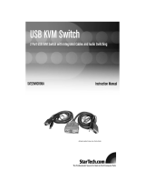
File Transfer
The IP KVM is able to emulate a virtual USB
disk drive on any connected host. Depending
on conguration, it will appear to the host as
a oppy drive (1.44MB), an 8MB RAM Disk or a
CD-ROM. The host computer does not require
any special drivers or other conguration. You
can transfer les to the virtual disk at any time.
The IP KVM will wait until the host is not using
the disk, and add or remove the les.
When the host computer next looks at the
drive, it will notice the changes. You can read
les from the virtual disk at any time, as long
as the host is not actively writing to the disk.
All of this happens in the background, and
you may treat the virtual disk as a shared drive
without any restrictions.
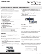
Access to the les is performed through the
web interface. Contents of the root directory are shown on the home page. You can
download les as you would any le on the web (right-click and Save target as).
To upload a le, click Browse, select a le, and then click Upload.
Files and directories may be deleted using the Delete button situated to their right.
When emulating a oppy disk or RAM Disk, the data is stored in RAM on the IP KVM
itself. In order to emulate a CD-ROM disk drive, a web server is required to provide
the CD-ROM image data. The Web server must be accessible to the unit, which
communicates with it constantly as data is needed.
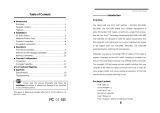
Floppy mode: Choose the Format as oppy button to switch to oppy mode. Under
Windows, the drive will be identied as a “high density oppy” and will typically be
assigned a drive letter of B:
The capacity is limited to 1.44 megabytes in this mode. The purpose of supporting
oppy mode is to permit the use of oppy-disk images generated by other systems
(e.g. the ash BIOS upgrade process is performed with a special oppy and is bootable,
Instruction Manual
10
emergency repair disks are often oppy-based etc.). You can transfer bits from that
oppy to the IP KVM (use the upload disk image form) and boot from the special
oppy.
CD-ROM Mode: The IP KVM does not store any data in this mode. Instead, it emulates
a USB CD-ROM drive with a disk inserted. The data from that disk must be provided by
an external web server. You will need a copy of the CD-ROM contents that you want to
emulate as an ISO le. This is a byte-for-byte copy of track one (the data track) of a data
CD-ROM. The ISO le must be made available on a web server that can be accessed by
the IP KVM. To switch to this mode, type in a URL pointing to the ISO image, and click
on Commit. The system will connect to the web server and test the le for access. If
successful, you will be shown a short report on the le contents, and the disk will be
ready to use.
Please note that the only way to preview or browse the contents of the CD-ROM
image, is from the host.
CD-ROM Web Server Requirements:
Data must be hosted on a web server that the IP KVM can access directly.
An image of a bootable CD-ROM disk can be used by the BIOS to boot an operating
system.
The image le itself may be any size, but it will typically be less than 700Mb.
Normally this le will be an ISO image (an ISO-9660 le system) but any disk image
may be used.
The web server must support “byte ranges”. Persistent connections are used, if
available, as this greatly improves performance. “Read-only access is provided;
writing is not supported.
CD-ROM block size must be 2048 bytes. XA-Data type tracks are not supported.
RAM Disk mode: Choose the Format as RAM Disk button to switch to RAM Disk mode.
This mode is intended to facilitate simple data transfer between the remote user and
the host computer. It will be recognized by Windows as an 8MB removable disk and
assigned a drive letter. You can easily drag and drop les up to 8MB in size to this
device.
Disk Formats: When you choose the Format as... button, the disk image stored in RAM
is formatted as an empty MS-DOS disk, with a single le called Put les here...TXT.
The IP KVM is able to read most MS-DOS/Windows formatted disks and presents the
les via the Web interface. However, disk emulation occurs at the lowest level, so other
disk formats can be used if you have the tools needed to create and read the disk
images.
At the bottom of the page are the upload and download options for the entire disk
image. Any image that is exactly 1,474,560 bytes long will be treated as a oppy.
Images of other sizes are supported up to 8MB.
Booting from USB Disk:
Instruction Manual
11
If the host computer’s BIOS supports USB boot devices, it is possible to boot from
the emulated CD-ROM or oppy - allowing complete operating system replacement
without any on-site intervention.
The rst step is getting a bootable disk image onto the emulated oppy or CD-ROM.
For CD-ROM images, you will need an .ISO image from a disk that contains special bits
to enable booting (“El Torito” standard). Nothing special is needed when reading the
ISO from a working, bootable CD-ROM.
Please note that each BIOS manufacturer oers varying levels of support for USB boot
devices and may require conguration methods that are unique (to the manufacturer)
in order to utilize this feature. Similarly, please note that many BIOS’s provide a
simplied USB host stack and oer drivers that may not oer suitable reliability.
To create a bootable oppy, you can format the emulated oppy from the target
system, or read the data from a working boot oppy. This can be done from Windows
using Disk Copy (right click on the drive letter in the Windows Explorer) or by using a
program like “RAWRITE”.
Once you have a bootable image (CD-ROM or oppy) working on the Enterprise Class
KVM unit, you must adjust your BIOS settings to tell it to boot from a USB device.
Please note: You must select USB CD-ROM as the boot device for the BIOS, if using a
CD-ROM image and USB Floppy if using a oppy image.
Network Conguration
DHCP: Automatic network conguration using DHCP is: Enabled/Disabled. This
feature applies only to the LAN port on the
rear panel, and is enabled by default. When
enabled, the unit will automatically congure
itself with an IP address when a DHCP server
is present. When disabled, the LAN port
will use the values assigned to it on the IP
Addresses and Routing table below.
IP Addresses and Routing: This table allows
you to assign IP information for the LAN and
WAN ports separately. If you are using DHCP,
the values for the LAN port will be lled in
automatically and any changes made will not
aect the setup.
Domain Name Server: This section allows
you to specify DNS servers and the default
DNS domain sux in use on the network. If
DHCP is enabled, some of these values may
be supplied automatically.
Instruction Manual
12
Clicking the Commit button applies any changes made on this page, but leaves the
old settings active until the next time the unit restarts. Clicking Make changes eective
now applies the changes and restarts the IP KVM so the new settings take eect
immediately.
Ethernet Address (MAC Address): This is the Ethernet hardware address of this units
LAN port. It is set at the factory and cannot be changed. You may need this number to
congure your DHCP server.
Dynamic DNS Conguration: Dynamic DNS (DDNS) is a method, protocol, or network
service that allows a networked device using the Internet Protocol Suite to notify
a domain name server to change, in real time, the active DNS conguration of its
congured hostnames, addresses or other information stored in DNS.
Numerous providers, called Dynamic DNS service providers, oer such technology
and services on the Internet. They provide a software client program that automates
this function. The client program is executed on a computer or device in the private
network. It connects to the service provider’s systems and causes those systems to link
the discovered public IP address of the home network with a hostname in the domain
name system. Depending on the provider, the hostname is registered within a domain
owned by the provider or the customers own domain name.
User Accounts
This menu will allow you to add accounts other than admin to the system. These
accounts will not have the authority to change settings, but can access the Web
interface and log into the VNC console.
Selecting Delete permanently removes
the user from the system. If you enter
values for a user that does not already
exist under Edit User Details, the system
will create that user for you when you
click Record changes. If the user already
exists, you may change the password for
that user.
Instruction Manual
13
System Identication
Machine Name: This is the name that is used to
uniquely identify this machine. You may wish to create
a DNS entry that matches this name. The name is
provided as the Client Name for the DHCP server. It is
also shown at the top of each page in the web browser
interface and is the desktop name” for VNC clients.
Other identication details: These values are for
information purposes. They are visible from the VNC
client and via SNMP (if enabled).
Location: This string is sent as the system.sysLocation
value over SNMP. It should describe the location of this
system.
Contact Name: This string is sent as the system.sys
Contact value over SNMP. It should describe who to contact regarding this machine.
Typically it includes an email address.
Network Address: This value is not used in our conguration, but is meant to store a
user-dened value that identies the controlled machine on the network. The ocial
DNS name of the controlled machine is an obvious value to put here, but you may use
it for any purpose.
Description: A user-dened description for the controlled machine.
Security
This menu allows you to congure a number of settings,
including the admin password. Be careful when making
any changes remotely, as altering these features could
make the unit inaccessible through Web conguration
(i.e. due to rewall ltering). Note that any password
changes you make will have to be entered twice to
protect against user error.
Instruction Manual
14
Compatibility
The Compatibility menu oers features
that may provide enhanced functionality
with certain KVM and power products, such
as StarTech.com’s Remote Power Switch
(PCM8155HNA). These can be left at their
default values if you are not connecting the
unit to a KVM or power management device.
SNMP
The SNMP menu allows you to congure the IP KVM so it can
be recognized and managed using industry standard Simple
Network Management Protocol software.
RADIUS
The RADIUS server requires the IP address,
the UDP port number (1812 - default or
1645) and the shared secret. The shared
secret is used to encrypt communications
and corresponds to a shared password for
the RADIUS server and the client machine.
Two additional servers may be dened for
backup purposes. Each server will be tried in
order using the indicated number of retries
and timeout period, which are congurable
on the same page.
Remember to enable RADIUS after conguring it. While RADIUS authentication is
enabled, the locally dened accounts on the Server Remote Control unit will not be
used, except for the SSH login. However, if a user name in the form “name.local” is
given at the RADIUS prompt, the system will use “name, check the password locally,
and skip RADIUS authentication. Delete all local accounts to avoid this behavior. When
connecting via VNC, a login screen is generated that asks for a RADIUS username and
password.
Instruction Manual
15
Modem
Enable this to allow the modem to answer
the phone and start a PPP connection. Enable
modem connections (PPP) via serial port/
modem.
Serial Ports
The Serial Ports menu allows you to manage
and connect to devices connected to the
unit using the R-Port on the IP KVM.
Time / Date
Date and time are stored without consideration for time
zone. If you are controlling multiple sites in dierent time
zones, we recommend you use UTC (Universal Coordinated
Time, also sometimes called GMT or Zulu) for all machines.
If the computer you are using to view this page knows the
correct time, just press the button to set the time and date
to that of your browser.
Firmware
The rmware on the IP KVM is eld upgradable. To upgrade to another version:
1. Login your IP KVM as “admin
2. Click “Firmware”
3. Click “Get latest version
4. Save the latest rmware le to your computer. It may take a few minutes for
downloading, depending on the speed of your network.
5. Upload the latest rmware le from your computer to the IP KVM. It will take more
than 5 minutes for uploading and writing it to the ash memory of the IP KVM.
  • Page 1 1
  • Page 2 2
  • Page 3 3
  • Page 4 4
  • Page 5 5
  • Page 6 6
  • Page 7 7
  • Page 8 8
  • Page 9 9
  • Page 10 10
  • Page 11 11
  • Page 12 12
  • Page 13 13
  • Page 14 14
  • Page 15 15
  • Page 16 16
  • Page 17 17
  • Page 18 18
  • Page 19 19
  • Page 20 20
  • Page 21 21
  • Page 22 22
  • Page 23 23
  • Page 24 24
  • Page 25 25
  • Page 26 26
  • Page 27 27
  • Page 28 28
  • Page 29 29
  • Page 30 30
  • Page 31 31
  • Page 32 32
  • Page 33 33
  • Page 34 34
  • Page 35 35
  • Page 36 36
  • Page 37 37
  • Page 38 38
  • Page 39 39
  • Page 40 40
  • Page 41 41
  • Page 42 42
  • Page 43 43
  • Page 44 44
  • Page 45 45
  • Page 46 46
  • Page 47 47
  • Page 48 48
  • Page 49 49
  • Page 50 50
  • Page 51 51
  • Page 52 52

StarTech.com SV441DUSBI User manual

Category
KVM switches
Type
User manual
This manual is also suitable for

Ask a question and I''ll find the answer in the document

Finding information in a document is now easier with AI