English
A2 A3
Product Features
Intro Operation Customer
Assistance
Warranty
Notice
Main Icons
Secondary Icons
Nothing Comes Close to a Cobra
®
49
Product Features
Accessories Order Info and
Trademark Acknowledgement
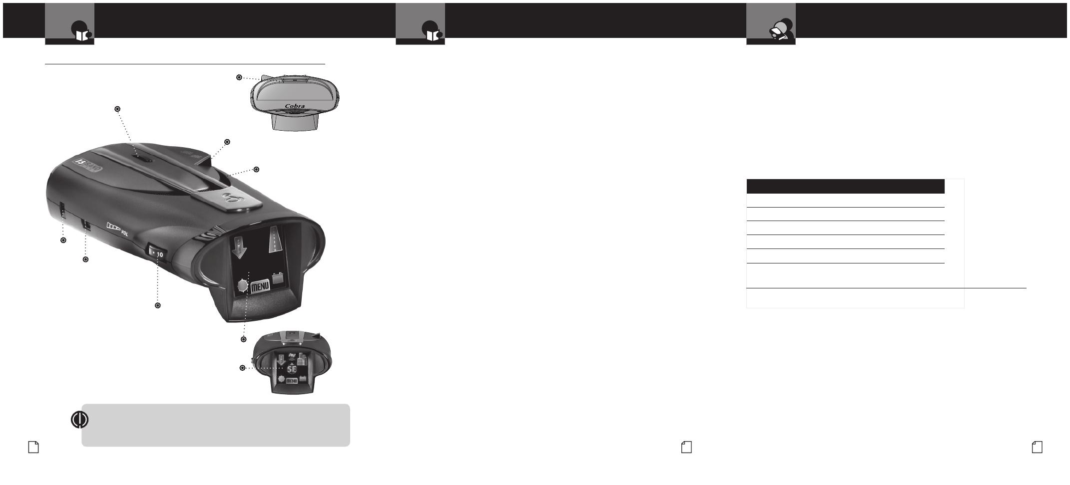
Controls, Indicators,
Connections and Display
Ordering From U.S.A.
Call 773-889-3087 for pricing or visit www.cobra.com.
For Credit Card Orders
Call 773-889-3087 [Press one from the main menu] 8:00 a.m. to 5:30 p.m.
Central Time, Monday through Friday.
Make Check or Money Order Payable To
Cobra Electronics, Attn: Accessories Dept.,
6500 West Cortland Street, Chicago, IL 60707 U.S.A.
To Order Online
Please visit our website: www.cobra.com
Item # Description
RDA GPSL66 Plug-in GPS Locator Unit
420-030-N-001 Straight 12V Power Cord
420-030-N-001 Coiled 12V Power Cord
545-159-N-001 Windshield Mounting Bracket
CLP-2B Dual Port Power Adapter
Trademark Acknowledgement
•
Cobra
®
, DigiView
®
, EasySet
®
, Extra Sensory Detection
®
, IntelliMute
®
, IntelliMute
®
Pro, IntelliShield
®
,
LaserEye
®
, Nothing Comes Close to a Cobra
®
, Safety Alert
®
Trafc Warning System, Strobe Alert
®
,
VG-2 Alert
®
, Xtreme Range Superheterodyne
®
and the snake design are registered trademarks of
Cobra Electronics Corporation, USA.
Cobra Electronics Corporation™, 14 Band™, 15 Band™, AURA™, Extreme Bright DataGrax™,
IntelliLink™, IntelliScope™, IntelliView™, Revolution™ Series, SmartPower™, Spectre Alert™,
Super-Xtreme Range Superheterodyne™, S-XRS™, UltraBright™, and Voice Alert™ are trademarks
of Cobra Electronics Corporation, USA.
Opticom™ is a trademark of 3M Corporation. Instaclear
®
for Ford is a registered trademark of Ford
Motor Company, Inc. Electriclear
®
for GM is a registered trademark of General Motors Corporation.
20-20™ and Ultra-Lyte™ are trademarks of Laser Technology, Inc. ProLaser™ and ProLaser III™
are trademarks of Kustom Signals, Inc. Bee III™ and Pop™ are a trademarks of MPH Industries.
Stalker™ LIDAR is a trademark of Applied Concepts, Inc. Spectre I™ and
Spectre IV™ are trademarks of Stealth Micro Systems Pty. Ltd. SpeedLaser™ is a trademark
of Laser Atlanta, LLC. Interceptor VG-2™ is a trademark of TechniSonic Industries LTD. Tomar
®
is a registered trademark of TOMAR Electronics, Inc.
Congratulations! You’ve made a smart choice by purchasing a maximum
performance digital radar/laser detector from Cobra. Just look at some of
the sophisticated features and capabilities your new unit includes:
Super-Xtreme Range
Superheterodyne Technology
With super-fast sweep circuitry, S-XRS provides
maximum detection range and the best possible
advance warning to even the fastest radar guns
Touchscreen Interface
Simple, intuitive touchscreen control
Maximum Performance
Provides advanced warning with maximum
detection range for total protection
Detection and Separate Alerts
For radar signals (X, K, Ka and Ku bands,
with signal strength indicated), Laser signals,
Safety Alert signals, Strobe Alert signals,
VG-2 signals, Spectre I & IV signals
LaserEye
For 360° detection of laser and strobe signals
Frequency Display Mode
Shows frequency of received Ka and Laser signals
Instant-On Ready
Detects radar guns with “instant-On”
(very fast) speed monitoring capabilities
Pop Detection
Detects the latest super-fast instant-on single
pulse radar guns
Voice or Tone Alert
With adjustable volume
ExtremeBright DataGrax
TM
Touchscreen Display
Easy-to-read graphical user interface and cool
3D graphics
IntelliShield False Signal Rejection
Reduces falsing in urban areas with Highway
mode and three levels of City mode settings
Safety Alert
Trafc warning system distinguishes important
safety alerts from other K band signals
Strobe Alert
Emergency vehicle warning system
Manual Mute or Auto Mute
A mute function of audio alerts
IntelliMute
A mute function which automatically reduces
false audio alerts by sensing engine RPMs
IntelliMute Pro
Prevents detection by radar detector detectors
(RDDs) when traveling at slower speeds
SmartPower
A timed power saving function that
saves your car’s battery
EasySet Menu
User-friendly mode selection and
setting with visual guidance
Car Battery Voltage
Displays your car battery voltage
Low Car Battery Voltage Warning
Alert can be provided when voltage goes
below 11.9 volts
Customizable Display Colors
Customize the display colors to match your dash
illumination
Auxiliary Audio Jack
For external speaker connection
AURA™ Database Updates
XRS 9970G includes GPS Locator & lifetime AURA
updates; XRS 9965 requires separate purchase
of GPS Locator (RDA GPSL 66)
and subscription to AURA database
GPS Ready (See page 34)
GPS Locator unit (included on XRS 9970G;
optional on XRS 9965) adds: Photo Enforced,
Caution, Known Speed Trap Areas and User
Locations and other GPS-based features
IntelliScope (requires GPS locator)
Uses GPS Locator to show direction of Location-
Based Alerts relative to your moving vehicle
IntelliView Pro (requires GPS locator)
Picture-in-picture shows: a) radar and
laser alerts simultaneously with GPS Locator
based location alerts; b) radar and laser
alerts and your current vehicle speed
Controls, Indicators, Connections and Display
•
Windshield Bracket
Mounting Slot
Windshield Bracket
Release Button
12V DC
Power
Jack
GPS Port
For connection
of GPS Locator.
(optional with
XRS 9965).
On-Off/Volume Control
Allows user to adjust the volume
of the tone and voice alerts.
ExtremeBright DataGraxTM Display
Full color and sunlight-readable, the extremely bright
display provides intuitive graphical information and alert
screens.
Touchscreen Interface
All unit controls are shown on the display and
activated with a simple nger touch.
Introduction Introduction
Intro Operation Customer
Assistance
Warranty
Notice
Main Icons
Secondary Icons
LaserEye
For 360° detection of
laser and strobe signals.
Auxiliary Audio Jack
On right side of unit.
Speaker
FCC NOTICE This device complies with part 15 of FCC rules: Operation is subject to
the following two conditions: (1) This device may not cause harmful interference, and
(2) This device must accept any interference received including interference that may
cause undesired operation.


