
Crestron Isys
®
TPS-12/15/17
Tilt Touchpanels
Operations Guide

This document was prepared and written by the Technical Documentation department at:
Crestron Electronics, Inc.
15 Volvo Drive
Rockleigh, NJ 07647
1-888-CRESTRON
All brand names, product names and trademarks are the property of their respective owners.
©2005 Crestron Electronics, Inc

Crestron Isys
®
TPS-12/15/17 Tilt Touchpanels
Contents
Crestron Isys
®
Tilt Touchpanels: TPS-12/15/17 1
Introduction ........................................................................................................................1
Features and Functions .............................................................................................................. 1
Specifications ............................................................................................................................ 3
Physical Description.................................................................................................................. 5
Tilt Angle Tension Adjustment ............................................................................................... 14
Industry Compliance................................................................................................................ 14
Setup.................................................................................................................................14
Network Wiring....................................................................................................................... 14
QuickMedia Network Wiring .................................................................................................. 15
Identity Code ........................................................................................................................... 16
Configuring the Touchpanel.................................................................................................... 16
Hardware Hookup.................................................................................................................... 24
Recommended Cleaning.......................................................................................................... 26
Programming Software.....................................................................................................27
Earliest Version Software Requirements for the PC................................................................ 28
Programming with Crestron System Builder........................................................................... 28
Programming with SIMPL Windows ...................................................................................... 29
Programming with VisionTools Pro-e ..................................................................................... 31
Hard Button Programming ...................................................................................................... 34
Reserved Join Numbers ...........................................................................................................34
MultiByte International Characters.......................................................................................... 42
Uploading and Upgrading.................................................................................................43
Establishing Communications ................................................................................................. 43
Troubleshooting Communications........................................................................................... 52
Uploading a SIMPL Windows Program .................................................................................. 52
Uploading a VT Pro-e Project ................................................................................................. 54
Firmware Upgrade................................................................................................................... 56
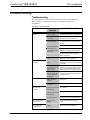
Problem Solving ...............................................................................................................59
Troubleshooting....................................................................................................................... 59
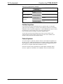
Further Inquiries ...................................................................................................................... 60
Future Updates......................................................................................................................... 60
Software License Agreement............................................................................................61
Return and Warranty Policies...........................................................................................63
Merchandise Returns / Repair Service..................................................................................... 63
CRESTRON Limited Warranty............................................................................................... 63
Operations Guide – DOC. 6375 Contents •
i


Crestron Isys
®
TPS-12/15/17 Tilt Touchpanels
Crestron Isys
®
Tilt Touchpanels:
TPS-12/15/17
Introduction
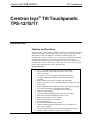
Features and Functions
The Crestron Isys
®
TPS-12, TPS-15 and TPS-17 family of tilt touchpanels offer high
brightness and contrast combined with a super wide viewing angle to deliver crisp,
detailed images under all conditions. For simplicity within this guide, these
touchpanels are referred to as TPS-12/15/17, except where noted. These touchpanels
are QuickMedia™ compatible. The features and specifications for all three
touchpanels are identical (except those relating to the screen). The touchpanels are
available with a variety of color bezels (ex. black with silver accent, white with gray
accent), and are designated with a -B or -W respectively.
Functional Summary
• 12, 15, and 17 inch (widescreen) active matrix color displays
• Screen resolutions: TPS-12 800 x 600, TPS-15 1024 x 768,
TPS-17 1280 x 768
• 16.7 million colors, 24-bit graphics with 8-bit alpha channel
• 128 MB of DDR RAM, 32 MB of internal flash (expandable to
160 MB)
• Built-in time-based correction for stable video and graphics
• Supports composite, S-video, and component inputs in both NTSC and
PAL formats
• Supports QuickMedia™ transport technology, which affords expanded
AV connectivity through a streamlined wiring solution
• Supports Crestron Home
®
CAT5 balanced AV connectivity
• Full screen video capability
• Up to 4,000 digital and analog signals; up to 999 serial signals
• Built-in microphone and biamplified speaker system
• Built-in audio amplifier, 5 W per channel
• Stores and plays back WAV sound files
• Stereo headphone jack
• Stereo audio input and microphone output
• 10BaseT/100BaseTX high-speed Ethernet, 802.3U compliant, full
duplex, auto switching
• Five backlit hard buttons (one reset and four programmable buttons)
•
Includes a TPMC
-
CH
-
IMC to facilitate A/V connections
Operations Guide – DOC. 6375 Tilt Touchpanels: TPS-12/15/17 ¥
1

Tilt Touchpanels Crestron Isys
®
TPS-12/15/17
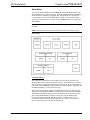
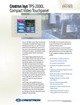
TPS-12/15/17 Block Diagram
Memory
The TPS-12/15/17 touchpanels feature 128 MB DDR RAM and 32 MB Flash, with a
built-in compact flash slot that allows flash memory expansion up to 160 MB.
Sound
Audio capabilities include 5 Watts per channel biamplified audio speakers that offer
built-in volume control, a built-in microphone and built-in WAV sound file
capability. Sound can be generated by the panel by using downloaded wave files
(.WAV) or can be mixed in from an external line level audio source or a QuickMedia
input. The TPS-12/15/17 touchpanels are also equipped with balanced output for
microphone audio that can be connected to a Crestron CNX-BIPAD8 or similar
Crestron CAT5 audio receiver.
Video
The TPS-12/15/17 touchpanels can display a single video window per page, and use
auto-detect for composite, S-video, component, NTSC and PAL formats. These
touchpanels support SDTV formats (does not support HD). Two video inputs
provide for connectivity to QuickMedia and PVID video distribution switches
(CNX-PVID8X3 or CNX-PVID8X4).
¥ Tilt Touchpanels: TPS-12/15/17 Operations Guide – DOC. 6375
2

Crestron Isys
®
TPS-12/15/17 Tilt Touchpanels
QuickMedia™
While acting as a QuickMedia (QM) receiver, the TPS-12/15/17 touchpanels can be
connected as an endpoint to a QM switching device or QM transmitter.
NOTE: The TPS-12/15/17 does not support RGB.
Connectivity
The TPS-12/15/17 touchpanels feature a Cresnet and a high-speed Ethernet port for
seamless communication with Crestron control systems, and computers. In addition,
a USB port is provided for future applications. The "RS-232 Port for Touch Output"
operation transmits touch coordinates to external devices via RS-232 for “Touch-
The-PC” and other functions.
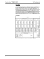
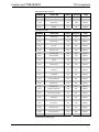
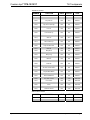
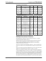
Specifications
The following table provides a summary of specifications for the TPS-12/15/17.
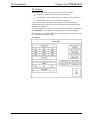
TPS-12/15/17 Specifications
SPECIFICATION DETAILS
Cresnet
®
Power Usage
Not including
TPMC-CH-IMC (1.0 W)
TPS-12 43 W (1.8 A @ 24 V) Supplied via NET port
TPS-15 65 W (2.7 A @ 24 V) Supplied via NET port
TPS-17 74 W (3.08 A @ 24 V) Supplied via NET port
Default Net ID 03
Timeout Adjustable from 0 to 120 minutes (Default = 10 min.)
Signal Join Maximums 4000 Digital, 4000 Analog, 999 Serial
Control System Update
Files
1, 2, 3
2-Series Control System
Version 3.137.CUZ or later
Touchpanel Firmware tps-12_tps-15_tps-17_1.xxx.xxxx.csf
Memory
32 MB Flash, 128 MB DDR RAM
Memory Expansion
Up to 160 MB via Compact Flash
Video
Full screen capable, standard definition formats
Auto detect of composite, S-video, component, NTSC, and PAL
16.7M colors
Time base correction & gamma correction
Supports 480i component video and 576i formats
Audio
Built-in microphone
Two built-in biamplified speakers (5 W per channel)
Stereo headphone output
Internal volume control and audio mixer
WAV file capability (8-bit PCM)
Continued on the following page
Operations Guide – DOC. 6375 Tilt Touchpanels: TPS-12/15/17 ¥
3

Tilt Touchpanels Crestron Isys
®
TPS-12/15/17
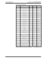
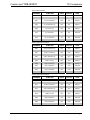
TPS-12/15/17 Specifications (continued)
SPECIFICATION DETAILS
Connectors
NET One 4-pin 5 mm detachable terminal block for connection to
Cresnet
USB One USB port (reserved for future applications)
RS-232 One 6-pin RJ-11 female connector, bi-directional RS-232 serial
connection, touchscreen output to PC or telestrator, or serial
mouse connection
Headphones One 3.5 mm stereo TRS mini phone jack, output power 12 mW,
impedance 32 Ohms (nominal)
QM IN One RJ-45 QuickMedia input connector
VIDEO IN One RJ-45 CNX-PVID differential video input connector
AUDIO I/O One RJ-45 CNX-BIPAD balanced stereo audio input and
microphone output connector
LAN One 8-wire RJ-45 Ethernet port with link/activity LED indicators,
10BaseT/100BaseTX high-speed Ethernet, TCP/IP, UDP/IP, CIP,
DHCP, 802.3U compliant, full duplex, auto switching
Buttons Five illuminated pushbuttons, the leftmost button (SW1) is
recessed and is a hardware reset used to reboot the touchpanel,
the four other buttons are user programmable
Display
Type Active Matrix Color LCD
Aspect Ratio TPS-12 4:3
TPS-15 4:3
TPS-17 15:9
Resolution TPS-12 800 x 600
TPS-15 1024 x 768
TPS-17 1280 x 768
Brightness TPS-12 400 nits
TPS-15 400 nits
TPS-17 450 nits
Contrast TPS-12 300:1
TPS-15 300:1
TPS-17 400:1
Illumination Backlit fluorescent
Viewing Angle TPS-12 +/- 70 degrees horizontal, +45/-55 degrees vertical
TPS-15 +/- 85 degrees horizontal and vertical
TPS-17 +/- 88 degrees horizontal and vertical
Tilt Angle 45 to 90 degrees
Enclosure Metal enclosure with a molded plastic bezel and integral rear
cover and cable strain relief
CPU 32-bit Motorola Coldfire
Processing Speed 410 MIPS
Operating Environment Temperature: 41° to 113°F (5° to 45°C)
Humidity: 10% to 90% RH (non-condensing)
Continued on the following page
¥ Tilt Touchpanels: TPS-12/15/17 Operations Guide – DOC. 6375
4

Crestron Isys
®
TPS-12/15/17 Tilt Touchpanels
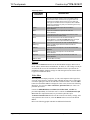
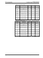
TPS-12/15/17 Specifications (continued)
SPECIFICATION DETAILS
TPS-12 Dimensions Height: 12.45 in (31.63 cm)
Width: 12.85 in (32.64cm)
Depth: 13.75 in (34.93 cm)
Weight: 12.95 lbs (5.88 kg)
TPS-15 Dimensions Height: 14.17 in (36.00 cm)
Width: 14.94 in (37.95 cm)
Depth: 13.75 in (34.93 cm)
Weight: 14.55 lbs (6.60 kg)
TPS-17 Dimensions Height: 14.17 in (36.00 cm)
Width: 17.63 in (44.79 cm)
Depth: 13.75 in (34.93)
Weight: 18.10 lbs (8.21 kg)
Accessories TPMC-CH-IMC interface unit
1 The latest software versions can be obtained from the Crestron website. Refer to the NOTE
following these footnotes.
2 Crestron 2-Series control systems include the AV2 and PRO2. Consult the latest Crestron Product
Catalog for a complete list of 2-Series control systems.
3 When loading VT Pro-e files or firmware through the RS-232 port of the control system, be sure that
the baud rate is at 38400 (Cresnet speed) or lower. Otherwise, Toolbox may post the “Transfer
Failed” message.
NOTE: Crestron software and any files on the website are for authorized Crestron
dealers and Crestron Authorized Independent Programmers (CAIP) only. New users
may be required to register to obtain access to certain areas of the site (including the
FTP site).
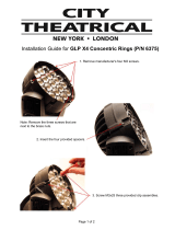
Physical Description
The electronic hardware is housed in a metal enclosure with a molded plastic bezel,
which is available in a variety of colors such as black with silver accent or white
with gray accent. This touchpanel is designed for placement on a tabletop or other
flat surface. All audio, RS-232, video, and network connections are made at the rear
panel on the base of the unit. A grille located on the front base of the unit conceals a
high frequency speaker; the low frequency speaker is in the base. The microphone is
located at the top center above the touchscreen. Five buttons (one reset and four
programmable) are located on the base.
Operations Guide – DOC. 6375 Tilt Touchpanels: TPS-12/15/17 ¥
5

Tilt Touchpanels Crestron Isys
®
TPS-12/15/17
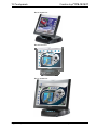
TPS-12 Angled View
TPS-15 Front View
TPS-17 Angled View
¥ Tilt Touchpanels: TPS-12/15/17 Operations Guide – DOC. 6375
6

Crestron Isys
®
TPS-12/15/17 Tilt Touchpanels
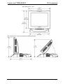
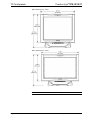
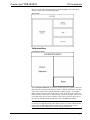
TPS-12 Physical View – Front
TPS-12 Physical Views – Side View at Maximum and Minimum Elevation
Operations Guide – DOC. 6375 Tilt Touchpanels: TPS-12/15/17 ¥
7

Tilt Touchpanels Crestron Isys
®
TPS-12/15/17
TPS-15 Physical View – Front
TPS-17 Physical View – Front
NOTE: The TPS-15 and TPS-17 are the same height.
¥ Tilt Touchpanels: TPS-12/15/17 Operations Guide – DOC. 6375
8

Crestron Isys
®
TPS-12/15/17 Tilt Touchpanels
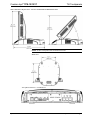
TPS-15 and TPS-17 Physical Views – Side View at Maximum and Minimum Elevation
NOTE: All three touchpanels share an identical base unit.
Bottom View
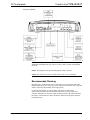
View of Rear Connectors – Cover Removed
Operations Guide – DOC. 6375 Tilt Touchpanels: TPS-12/15/17 ¥
9

Tilt Touchpanels Crestron Isys
®
TPS-12/15/17
Ports and Pushbuttons
All connections to the TPS-12/15/17 are made through the ports on the rear panel.
Refer to the illustrations and descriptions that follow.
NOTE: Rear ports are not accessible after the cover is replaced.
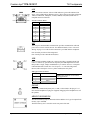
RS-232
This 6-pin RJ-11 connector mates with a 9-pin serial port of a PC. The connecting
cable is not supplied. Use this port to establish a direct connection between the
touchpanel and a PC without a control system or network connection. Once the direct
connection is established, touchpanel files and firmware updates can be uploaded to
the touchpanel. Additionally, the touchpanel’s diagnostic tools can be accessed over
the direct connection. In the event that modular cables or an RJ-11 to DB9F adapter
is not available, the following table and diagram provide information so that the cable
can be fabricated on site. Refer to “RS-232 Menu” on page 20 for RS-232 port
configuration settings.
RS-232 Pinouts
PIN # DESCRIPTION
1 CTS
2 GND
3 RXD
4 TXD
5 RTS
6 N/C (Not connected)
16
1
6
Front
Top
PC to TPS-12/15/17 Cable Specifications (Crestron Cable Number STCP-502PC)
¥ Tilt Touchpanels: TPS-12/15/17 Operations Guide – DOC. 6375
10

Crestron Isys
®
TPS-12/15/17 Tilt Touchpanels
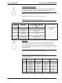
LAN
LAN
One 8-wire RJ-45 connector with two LED indicators (green LED indicates link
status, yellow LED indicates Ethernet activity). This connector provides an Ethernet
10baseT /100baseTX, full duplex, TCP/IP, UDP/IP, CIP, DHCP, IEEE 802.3U
compliant network connection.
Network Connector Pinout
PIN SIGNALS
1 TX +
2 TX -
3 RC+
4 N/C
5 N/C
6 RC -
7 N/C
8 N/C
NET
The four-pin 5 mm detachable terminal block provides communication with and
power from a Cresnet control network. For additional details, refer to “Network
Wiring” on page 14. A cable for this connection is provided with the touchpanel.
Pins 24 and G provide 24 VDC and ground.
Pins Y and Z provide communications (data).
USB
One Universal Serial Bus (USB) “B” connector provides a communications link.
USB is a connectivity specification developed by the USB Implementers Forum
that provides a single, simple, standardized way to connect devices to a computer.
USB shielded cables contain two wires for power +5 volts (red) and ground
(brown) and a twisted pair of wires (yellow and blue) that carry data.
USB Type B Connector Pinout
PIN DESCRIPTION
1 +5 VDC
2 Data -
3 Data +
4 Ground
NOTE: This connector is reserved for
future applications.
PHONE
Connect this standard mini phone jack (12 mW, 32 ohm load) to the plug of a 3.5
mm external headphone set plug (not supplied). Plugging in the headphone cuts off
the speakers.
MEMORY EXPANSION
The onboard memory may be enhanced with the addition of a Type II compact flash
memory (up to 160 MB).
The flash memory slot is accessible on the rear panel of the unit.
Operations Guide – DOC. 6375 Tilt Touchpanels: TPS-12/15/17 ¥
11

Tilt Touchpanels Crestron Isys
®
TPS-12/15/17
QM IN (QuickMedia Input)
The eight-pin RJ-45 QuickMedia transport port accepts Crestron Certified Wiring
carrying audio, video, and microphone signals. The QM input port conforms to the
568B wiring standard. Refer to the following table for connector pinouts.
NOTE: The QM port is not connected through any “IMC” interface.
NOTE: Only one video source may be displayed at a time.
NOTE: These touchpanels do not support RGB.
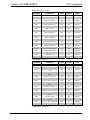
RJ-45 QuickMedia Connector Pin Assignments
RJ-45 PIN
NUMBER
WIRE COLORS
(EIA 568B)
QM ASSIGNMENT COMPOSITE,
S-VIDEO, COMPONENT AND
AUDIO
1 WHITE/ORANGE - CHROMINANCE (- P
R
)
2 ORANGE + CHROMINANCE (+ P
R
)
3 WHITE/GREEN - LUMINANCE (- Y)
4 BLUE + AUDIO
5 WHITE/BLUE - AUDIO
6 GREEN + LUMINANCE (+ Y)
7 WHITE/BROWN - COMPOSITE (- P
B
)
8 BROWN + COMPOSITE (+ P
B
)
RJ-45 MALE CONNECTOR
VIDEO IN
This eight-pin RJ-45 connection provides connectivity to the CNX-PVID or the
TPMC-CH-IMC interface module. This port provides component, composite or
S-video balanced input to the touchpanel over Crestron Certified Wiring. Description
of the pinouts is shown in the following table. A cable for this connection is provided
with the touchpanel.
CAUTION: Only use the TPMC-CH-IMC Interface Module when connecting this
port. Use of other “IMC” products could damage the panel.
NOTE: Only one video source may be displayed at a time.
Video In Pin Assignments
PIN WIRE COLORS
(568B)
COMPOSITE S-VIDEO COMPONENT
1 WHITE/ORANGE + Composite + Luminance + Y
2 ORANGE - Composite - Luminance - Y
3 WHITE/GREEN N/A + Chrominance + P
B
4 BLUE N/A N/A + P
R
5 WHITE/BLUE N/A N/A - P
R
6 GREEN N/A - Chrominance - P
B
7 WHITE/BROWN N/A N/A N/A
8 BROWN N/A N/A N/A
¥ Tilt Touchpanels: TPS-12/15/17 Operations Guide – DOC. 6375
12

Crestron Isys
®
TPS-12/15/17 Tilt Touchpanels
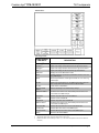
AUDIO I/O
This 8-pin RJ-45 connector provides connectivity to the CNX-BIPAD or with the
TPMC-CH-IMC interface module. This port uses Crestron Certified Wiring and
provides audio input to the touchpanel and microphone output from the touchpanel.
A description of the pinouts is shown in the following table.
CAUTION: Only use the TPMC-CH-IMC Interface Module when connecting this
port. Use of other “IMC” products could damage the panel.
Audio In/Out Pin Assignments
PIN WIRE COLORS (568B) AUDIO I/O
1 WHITE/ORANGE + Mic Left Out
2 ORANGE - Mic Left Out
3 WHITE/GREEN + Mic Right Out
4 BLUE + Audio Left In
5 WHITE/BLUE - Audio Left In
6 GREEN - Mic Right Out
7 WHITE/BROWN + Audio Right In
8 BROWN - Audio Right In
Pushbuttons
Five pushbuttons are located on the top of the base as shown in the following
diagram. The leftmost button is recessed and is a hard reset used to reboot the
touchpanel. The other four buttons are programmable. Refer to page 34 for hard
button programming information.
TPS-12/15/17 Pushbuttons
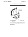
TPMC-CH-IMC Interface Module
For networks without CAT5 audio and video, the TPMC-CH-IMC is included to
convert unbalanced video sent over coax cable and balanced/unbalanced audio sent
over shielded, twisted-pair wiring to Crestron Certified Wiring for connection to the
touchpanels.
NOTE: The TPMC-CH-IMC is not for use with QuickMedia.
Operations Guide – DOC. 6375 Tilt Touchpanels: TPS-12/15/17 ¥
13

Tilt Touchpanels Crestron Isys
®
TPS-12/15/17
Tilt Angle Tension Adjustment
Use a 5/32 inch socket (supplied by other) with a hex drive key (Allen wrench) to
increase or decrease pivot tension at the base of the touchscreen. Turning the key
clockwise increases tension, counterclockwise decreases tension.
Tension Adjustment Screw
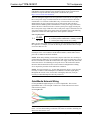
Industry Compliance
As of the date of manufacture, the TPS-12, TPS-15, and TPS-17 have been tested
and found to comply with specifications for CE marking and standards per EMC and
Radiocommunications Compliance Labelling.
NOTE: This device complies with part 15 of the FCC rules. Operation is subject to
the following two conditions: (1) this device may not cause harmful interference, and
(2) this device must accept any interference received, including interference that may
cause undesired operation.
Setup
Network Wiring
CAUTION: In order to ensure optimum performance over the full range of your
installation topology, Crestron Certified Wire, and only Crestron Certified Wire, may
be used. Failure to do so may incur additional charges if support is required to
identify performance deficiencies as a result of using improper wire.
CAUTION: Use only Crestron power supplies for Crestron equipment. Failure to
do so could cause equipment damage or void the Crestron warranty.
¥ Tilt Touchpanels: TPS-12/15/17 Operations Guide – DOC. 6375
14

Crestron Isys
®
TPS-12/15/17 Tilt Touchpanels
CAUTION: Provide sufficient power to the system. Insufficient power can lead to
unpredictable results or damage to the equipment. Please use the Crestron Power
Calculator to help calculate how much power is needed for the system
(http://www.crestron.com/calculators
).
When calculating the length of wire for a particular Cresnet run, the wire gauge and
the Cresnet power usage of each network unit to be connected must be taken into
consideration. Use Crestron Certified Wire only. If Cresnet units are to be daisy-
chained on the run, the Cresnet power usage of each network unit to be daisy-
chained must be added together to determine the Cresnet power usage of the entire
chain. If the unit is a home-run from a Crestron system power supply network port,
the Cresnet power usage of that unit is the Cresnet power usage of the entire run. The
wire gauge and the Cresnet power usage of the run should be used in the following
equation to calculate the cable length value on the equation’s left side.
Cable Length Equation
40,000
Where:
R x P
L <
L = Length of run (or chain) in feet.
R = 6 Ohms (Crestron Certified Wire: 18 AWG (0.75 MM
2
))
P = Cresnet power usage of entire run (or chain).
Make sure the cable length value is less than the value calculated on the right side of
the equation. For example, a Cresnet run drawing 20 watts should not have a length
of run more than 333 feet.
NOTE: All Crestron certified Cresnet wiring must consist of two twisted pairs. One
twisted pair is the +24V conductor and the GND conductor, and the other twisted
pair is the Y conductor and the Z conductor.
NOTE: When daisy-chaining Cresnet units, strip the ends of the wires carefully to
avoid nicking the conductors. Twist together the ends of the wires that share a pin on
the network connector, and tin the twisted connection. Apply solder only to the ends
of the twisted wires. Avoid tinning too far up the wires or the end becomes brittle.
Insert the tinned connection into the Cresnet connector and tighten the retaining
screw. Repeat the procedure for the other three conductors.
NOTE: For larger networks (i.e., greater than 28 network devices), it may become
necessary to add a Cresnet Hub/Repeater (CNXHUB) to maintain signal quality
throughout the network. Also, for networks with lengthy cable runs, it may be
necessary to add a Hub/Repeater after only 20 devices.
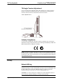
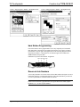
QuickMedia Network Wiring
For the QuickMedia (QM) transport, use CresCAT-QM cable. The Crestron
QuickMedia cable “CresCAT-QM” contains one CAT5E cable and one Cresnet
cable in siamese jackets.
CresCAT-QM Cable
NOTE: Do not untwist the two wires in a single pair for more than 1/3-1/2"
(0.84 – 1.27 cm) when making a connection. The twists are critical to canceling out
interference between the wires.
Operations Guide – DOC. 6375 Tilt Touchpanels: TPS-12/15/17 ¥
15

Tilt Touchpanels Crestron Isys
®
TPS-12/15/17
The aggregate cable length of a signal path originating at a QM transmitter and
terminating at the TPS-12/15/17 must not exceed 328 feet (100 meters). Video
signals may experience a loss of quality over very long lengths of cable. This
phenomenon is due to the added resistance and capacitance of longer cable lengths,
and is not particular to either Crestron and/or QuickMedia systems. To ensure
sufficient bandwidth, the maximum aggregate cable length should not exceed 328
feet. The use of lower-resolution signals may allow increased cable length but must
be tested by the installer with the sources to be used. The QM pin assignment is
based on the EIA/TIA 568B RJ-45 Jack standard.
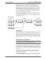
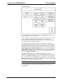
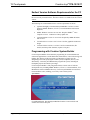
When connecting multiple QM devices, the route between a QM origination point
(transmitter) and a QM endpoint (receiver) cannot have more than two midpoints
(e.g., QM-MD7x2 or other QM switchers). Refer to the following diagram when
configuring a QM network.
QM Network Topology
Identity Code
All equipment and user interfaces within the network require a unique identity code
(Net ID). These codes are two-digit hexadecimal numbers ranging from 03 to FE
(Net ID 02 is reserved for control processors). The Net ID of each unit must match
an ID code specified in the SIMPL Windows program. The Net ID is set using the
internal setup menu (refer to “Interface Menu” on page 18). The Net ID may also be
changed using Crestron Toolbox (refer to “Establishing Communications” on page
43).
Configuring the Touchpanel
NOTE: The only connection required to configure the touchpanel is power (supplied
via Cresnet). Refer to “Hardware Hookup” on page 24 for details.
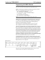
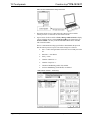
To configure the unit, it may be necessary to access a series of setup screens prior to
viewing run-time screens that are loaded into the touchpanel for normal operation.
The MAIN MENU for configuring the touchpanel appears when a finger is held to
the touchscreen as power is applied, or after the hardware reset button is pressed and
released. Remove your finger when the message "SETUP MODE" briefly appears on
the touchscreen.
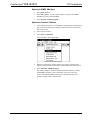
Upon entering SETUP MODE, the MAIN MENU, as shown in the following
illustration, displays four buttons: Touch Screen Calibration, Exit and Run
Program, Setup, and Diagnostics.
The Exit and Run Program button verifies that all of the setup information has
been saved to the EEPROM and displays the main page that has been programmed
¥ Tilt Touchpanels: TPS-12/15/17 Operations Guide – DOC. 6375
16
Page is loading ...
Page is loading ...
Page is loading ...
Page is loading ...
Page is loading ...
Page is loading ...
Page is loading ...
Page is loading ...
Page is loading ...
Page is loading ...
Page is loading ...
Page is loading ...
Page is loading ...
Page is loading ...
Page is loading ...
Page is loading ...
Page is loading ...
Page is loading ...
Page is loading ...
Page is loading ...
Page is loading ...
Page is loading ...
Page is loading ...
Page is loading ...
Page is loading ...
Page is loading ...
Page is loading ...
Page is loading ...
Page is loading ...
Page is loading ...
Page is loading ...
Page is loading ...
Page is loading ...
Page is loading ...
Page is loading ...
Page is loading ...
Page is loading ...
Page is loading ...
Page is loading ...
Page is loading ...
Page is loading ...
Page is loading ...
Page is loading ...
Page is loading ...
Page is loading ...
Page is loading ...
Page is loading ...
Page is loading ...
-
 1
1
-
 2
2
-
 3
3
-
 4
4
-
 5
5
-
 6
6
-
 7
7
-
 8
8
-
 9
9
-
 10
10
-
 11
11
-
 12
12
-
 13
13
-
 14
14
-
 15
15
-
 16
16
-
 17
17
-
 18
18
-
 19
19
-
 20
20
-
 21
21
-
 22
22
-
 23
23
-
 24
24
-
 25
25
-
 26
26
-
 27
27
-
 28
28
-
 29
29
-
 30
30
-
 31
31
-
 32
32
-
 33
33
-
 34
34
-
 35
35
-
 36
36
-
 37
37
-
 38
38
-
 39
39
-
 40
40
-
 41
41
-
 42
42
-
 43
43
-
 44
44
-
 45
45
-
 46
46
-
 47
47
-
 48
48
-
 49
49
-
 50
50
-
 51
51
-
 52
52
-
 53
53
-
 54
54
-
 55
55
-
 56
56
-
 57
57
-
 58
58
-
 59
59
-
 60
60
-
 61
61
-
 62
62
-
 63
63
-
 64
64
-
 65
65
-
 66
66
-
 67
67
-
 68
68


Crestron TPS-15 User manual
- Category
- PC/workstation barebones
- Type
- User manual
Ask a question and I''ll find the answer in the document
Finding information in a document is now easier with AI
Related papers
-
Crestron TPS-6X-FP User manual
-
-
-
-
-
-
-
-
-
Other documents
-
 Crestron electronic Residential Lighting User manual
-
 Crestron electronic TPS-GA-TPI User manual
-
 Crestron electronic TPS Series User manual
-
Shure DFR22 User manual
-
 Crestron electronic TPS-15L User manual
-
 Sunwave Tech. SRC-3310/9320 User manual
-
 Crestron electronic 2000L User manual
-
 Z Wave Products ZWP-TBX User manual
-
 City Theatrical 6375 GLP X4 Concentric Rings Installation guide
-
Fishman Isys III User manual


