
User Manual
CS-1004
CS-1008
CS-1016
2001-06-9

NOTE: This equipment has been tested and found to comply with the limits
for a Class B digital device pursuant to Subpart J of Part 15 of FCC Rules.
These limits are designed to provide reasonable protection against harmful
interference in a residential installation. This equipment generates, uses and
can radiate radio frequency energy and, if not installed and used in
accordance with the instructions, may cause harmful interference to radio
communications. However, there is no guarantee that interference will not
occur in a particular installation. If this equipment does cause harmful
interference to radio or television reception, which can be determined by
turning the equipment off and on, the user is encouraged to try to correct the
interference by one or more of the following measures:
! Reorient or relocate the receiving antenna
! Increase the separation between the equipment and receiver.
! Connect the equipment into an outlet on a circuit different from that
which the receiver is connected.
! Consult the dealer or an experienced radio/television technician for help
2001-06-9
ii. CS-1004 / CS1008 / CS-1016 User Manual

Packing List
The complete Master View package consists of:
!
One Master View KVM Switch (CS-1004, CS-1008, or CS-1016)
!
One Power Adapter
!
One User Manual
Check to make sure that the unit was not damaged in shipping. If you
encounter a problem, contact your dealer.
Read this manual thoroughly and follow the installation and operation
procedures carefully to prevent any damage to the unit, and/or any of
the devices connected to it.
©Copyright 2000 ATEN International Co., Ltd.
Manual Part No. PAPE-0150-400
Printed in Taiwan 05/2001
All brand names and trademarks are the registered property of their respective owners.
2001-06-9
CS-1004 / CS1008 / CS-1016 User Manual iii.

Contents
Overview . . . . . . . . . . . . . . . . . . . . . . . . . . . . . . . . . . . . . . . . . . . . . . . . . . . . . . 1
Features. . . . . . . . . . . . . . . . . . . . . . . . . . . . . . . . . . . . . . . . . . . . . . . . . . . . . . . 2
Hardware Requirements . . . . . . . . . . . . . . . . . . . . . . . . . . . . . . . . . . . . . . . . . . 3
Console . . . . . . . . . . . . . . . . . . . . . . . . . . . . . . . . . . . . . . . . . . . . . . . . . . . . 3
PC . . . . . . . . . . . . . . . . . . . . . . . . . . . . . . . . . . . . . . . . . . . . . . . . . . . . . . . . 3
Cables . . . . . . . . . . . . . . . . . . . . . . . . . . . . . . . . . . . . . . . . . . . . . . . . . . . . . 4
Introduction . . . . . . . . . . . . . . . . . . . . . . . . . . . . . . . . . . . . . . . . . . . . . . . . . . . . 5
Front View . . . . . . . . . . . . . . . . . . . . . . . . . . . . . . . . . . . . . . . . . . . . . . . . . . 5
Rear View. . . . . . . . . . . . . . . . . . . . . . . . . . . . . . . . . . . . . . . . . . . . . . . . . . . 6
Installation . . . . . . . . . . . . . . . . . . . . . . . . . . . . . . . . . . . . . . . . . . . . . . . . . . . . . 7
Before you Begin . . . . . . . . . . . . . . . . . . . . . . . . . . . . . . . . . . . . . . . . . . . . . 7
Single Station Installation. . . . . . . . . . . . . . . . . . . . . . . . . . . . . . . . . . . . . . . 7
Daisy Chaining. . . . . . . . . . . . . . . . . . . . . . . . . . . . . . . . . . . . . . . . . . . . . . . 9
Operation. . . . . . . . . . . . . . . . . . . . . . . . . . . . . . . . . . . . . . . . . . . . . . . . . . . . . 11
Hot Plugging. . . . . . . . . . . . . . . . . . . . . . . . . . . . . . . . . . . . . . . . . . . . . . . . 11
Powering On/Off and Restarting . . . . . . . . . . . . . . . . . . . . . . . . . . . . . . . . 12
Port Selection. . . . . . . . . . . . . . . . . . . . . . . . . . . . . . . . . . . . . . . . . . . . . . . 13
OSD Operation . . . . . . . . . . . . . . . . . . . . . . . . . . . . . . . . . . . . . . . . . . . . . . . . 14
OSD Overview . . . . . . . . . . . . . . . . . . . . . . . . . . . . . . . . . . . . . . . . . . . . . . 14
Port Numbering . . . . . . . . . . . . . . . . . . . . . . . . . . . . . . . . . . . . . . . . . . . . . 15
OSD Navigation . . . . . . . . . . . . . . . . . . . . . . . . . . . . . . . . . . . . . . . . . . . . . 15
OSD Main Menu Headings . . . . . . . . . . . . . . . . . . . . . . . . . . . . . . . . . . . . 16
The Function Keys. . . . . . . . . . . . . . . . . . . . . . . . . . . . . . . . . . . . . . . . . . . 16
Factory Default Settings. . . . . . . . . . . . . . . . . . . . . . . . . . . . . . . . . . . . . . . 23
OSD Security . . . . . . . . . . . . . . . . . . . . . . . . . . . . . . . . . . . . . . . . . . . . . . . 23
Appendix . . . . . . . . . . . . . . . . . . . . . . . . . . . . . . . . . . . . . . . . . . . . . . . . . . . . . 24
Master View - Computer Connection Table. . . . . . . . . . . . . . . . . . . . . . . . 24
Station Numbering Table. . . . . . . . . . . . . . . . . . . . . . . . . . . . . . . . . . . . . . 25
Troubleshooting . . . . . . . . . . . . . . . . . . . . . . . . . . . . . . . . . . . . . . . . . . . . . 26
Specifications. . . . . . . . . . . . . . . . . . . . . . . . . . . . . . . . . . . . . . . . . . . . . . . 27
Limited Warranty . . . . . . . . . . . . . . . . . . . . . . . . . . . . . . . . . . . . . . . . . . . . 28
2001-06-9
iv. CS-1004 / CS1008 / CS-1016 User Manual

Overview
The Master View KVM Switch is a control unit that allows access to
multiple computers from a single console (keyboard, monitor, and
mouse). Before the development of the Master View, the only way to
control multiple computer configurations from a single console was
through a complex and costly network system. Now, with the Master
View, you can easily access multiple computers in a cost effective
manner.
Depending on the model a Master View unit can control up to 4, 8, or 16
computers. Up to 31 additional Master Views can be daisy chained (for
a total of up to 32 units), which means that up to 128, 256, or 512
computers can all be controlled from a single keyboard-monitor-mouse
console.
Setup is fast and easy; plugging cables into their appropriate ports is all
that is entailed. There is no software to configure, so there is no need to
get involved in complex installation routines or be concerned with
incompatibility problems. Since the Master View intercepts keyboard
input directly, it works on any hardware platform and with all operating
systems.
The Master View provides two convenient methods to access any
computer connected to the system: using the port selection switches
located on the front panel and using the menu driven OSD (On Screen
Display) feature with mouse or keyboard.
A powerful Quick View Scan Mode feature allows you to auto scan and
monitor the activities of all operating computers on the installation one
by one. Responding to the growing use of multimedia in the workstation
space, the Master View has been designed with built in microphone and
speaker support - a feature that will be increasingly essential over time.
By allowing a single console to manage all the attached computers, the
Master View eliminates the expense of purchasing a separate
keyboard, monitor, and mouse for each computer as well as saving all
the space they would take up. It also eliminates the inconvenience and
wasted effort involved in constantly moving around from one computer
to another.
2001-06-9
CS-1004 / CS-1008 / CS-1016 User Manual 1

Features
!
Special ASIC Technology - Enhances Compatibility and Reliability
!
Daisy Chain Up To 31 Additional Units - Control Up to 128, 256, or
512 Computers From a Single Console
!
No Software Required - Computer Selection via Front Panel
Switches or OSD
!
Broadcast Function - Used to Install Software on Multiple Computer
Systems or Shut Them All Down.
!
Quick View Scan Mode for Monitoring Selected computers
!
PS/2 and Serial Mouse Emulation Provided For System Bootup
!
Console’s PS/2 Mouse Controls All Connected Computers - Even
Those With Serial Mice
!
Support Microsoft Intellimouse Pro, Logitech FirstMouse, MouseMan.
!
SVGA, VGA and Multisync Monitor Support
!
LED Display For Easy Status Monitoring
!
Rack Mountable in 19" System Rack
!
Audio Support Built In
2001-06-9
2 CS-1004 / CS-1008 / CS-1016 User Manual

Hardware Requirements
Console
!
A VGA, SVGA, or Multisync monitor capable of the highest
resolution that you will be using on any computer in the installation.
!
A PS/2 style mouse
!
A PS/2 style keyboard
PC
The following equipment must be installed on each computer:
!
A VGA, SVGA or Multisync card.
!
Either a 6-pin mini-DIN (PS/2 style), or DB-9 (standard serial),
mouse port.
!
Either a 6-pin mini-DIN (PS/2 style) keyboard port with +5V DC on
pin 4 and Ground on pin 3, or a 5-pin DIN (AT style) keyboard port
with +5V DC on pin 5 and ground on pin 4.
2001-06-9
CS-1004 / CS-1008 / CS-1016 User Manual 3

Cables
For optimum signal integrity and to simplify the layout, we strongly
recommend that you use the following high quality CS Custom Cable
sets:
Connector Type CS Custom Cable
AT (5 pin DIN) Keyboard and Serial Mouse 2L-1701P + Keyboard & Mouse Adapters
PS/2 (6 pin mini-DIN) Keyboard and Mouse
2L-1701P
Daisy Chained Units
2L-1700
Note: The keyboard and the mouse cables have PS/2 style connector at
each end:
!
If your computer uses a standard AT style keyboard socket and
standard 9 pin serial ports, you will need to purchase a PS/2-to-AT
keyboard adapter (Part No. 2A-106, or any standard keyboard
adapter), and a PS/2-to Serial mouse adapter (Part No. 2A-105; a
standard mouse adapter will not work) in order to plug the cable into
the computer’s keyboard port.
!
Because of the wiring and the pin assignments, you cannot use a
Serial-to-PS/2 adapter at the end that plugs into the Master View.
Therefore attempting to use a standard cable extender with adapters
at both ends will fail.
2001-06-9
4 CS-1004 / CS-1008 / CS-1016 User Manual

Introduction
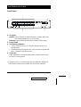
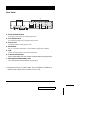
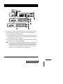
Front View *
1. Port LEDs
OnLine: Lights ORANGE to indicate that the computer attached to
the corresponding port is up and running
Selected: Lights GREEN to indicate the currently selected port.
2. Power Switch
3. Port Selection Switches
! Press a switch to access the computer attached to the corre-
sponding port.
! Simultaneously pressing Switches 1 and 2 for three seconds per-
forms a Keyboard and Mouse reset.
4. Power LED
Lights ORANGE to indicate that the Master View has been turned
On and is receiving power.
* The figure shows a CS-1016 model. The only difference between it
and the other models is the number of Port Selection Switches.
K/M Reset
1
2
3
4
2001-06-9
CS-1004 / CS-1008 / CS-1016 User Manual 5

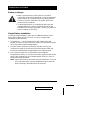
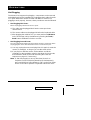
Rear View *
1. Daisy Chain Selection
If you daisy chain units, the cables plug in here.
2. CPU Port Section
The cables that link to the computers plug in here.
3. Power Jack
The power adapter cable plugs in here
4. DIP Switch
SW 1 - 5: Sets the Station No. (see the table on page 25 for details)
5. Link
Link is reserved and has no function at this time.
6. Console Port Section
If this is a first station unit, your monitor, keyboard and mouse plug in here.
7. Microphone and Speaker Jacks
Your microphone and speakers plug in here.
* The figure shows a CS-1016 model. The only difference between it
and the other models is the number of CPU Ports.
1 2
3
45 6
7
2001-06-9
6 CS-1004 / CS-1008 / CS-1016 User Manual

Installation
Before you Begin
1. Make sure that power to all the devices you will be
connecting up have been turned off. You must unplug the
power cords of any computers that have the Keyboard
Power On function. Otherwise, the switch will receive
power from the computer.
2. To prevent damage to your equipment due to ground
potential difference, make sure that all devices on the
installation are properly grounded. Consult your dealer for
technical details, if necessary.
Single Station Installation
In a Single Stage installation, there are no additional Master View’s
daisy chained down from the first unit. To set up a single stage
installation do the following:
1. Set Switches 1 - 5 of the Master View’s DIP Switch to the ON
position to set this unit up as the First Station (see the table on page
25 for Dip Switch Station Setting details).
2. Plug the monitor, keyboard, and mouse into the Console port
connectors located on the left rear panel of the Master View unit.
Each port is labeled with an appropriate icon to indicate itself.
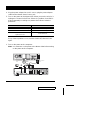
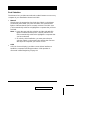
3. Use connector cable sets (as described in the Hardware
Requirements section), to connect the monitor, keyboard and mouse
ports of the computers to any available Master View CPU Port, as
shown in the diagram below.
Note: Ignore the Chain In and Chain Out Ports at this time. They are
only used when daisy chaining additional Master View units.
Daisy Chaining is described in the next section.
2001-06-9
CS-1004 / CS-1008 / CS-1016 User Manual 7

4. Plug the power adapter into an AC source; plug the power adapter
cable into the Master View’s Power Jack.
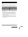
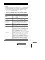
5. Turn on the power to the Master View. When you turn the unit On, it
undergoes a Power On Self Test. If there is a problem, Port LEDs 1 -
4 flash repeatedly according to a pattern that indicates what the
problem is:
Pattern Indication
LEDs 1 - 4 Flash Simultaneously Internal RAM Memory Error
LEDs 1 - 4 Flash One After the Other External RAM Memory Error
LEDs 1 + 2, and LEDs 3 + 4 Alternately
Light and Go Off
ROM Test Error
If any of these problems occur, turn the Switch Off, then turn it On
again.
1. Turn on the power to the computers.
Note: You must turn on the power to the Master View before turning
on the power to the computers.
PS/2 KEYBOARD
PORT
PS/2
MOUSE
PORT
VGA MONITOR
PORT
VGA MONITOR
PS/2 KEYBOARD
PS/2 MOUSE
Power Adapter
DIP Switch
2001-06-9
8 CS-1004 / CS-1008 / CS-1016 User Manual

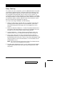
Daisy Chaining
To control even more computers, up to 31 additional Master View units
can be daisy chained from the Chain port of the First Stage unit. The
daisy chained Master Views that connect back to the First Stage unit
are considered Second Stage units. As many as 8 (CS-1004), 16
(CS-1008) or 32 (CS-1016) computers can be controlled in a complete
two stage installation. A table showing the relation between the number
of computers and the number of Master View units needed to control
them is provided in the Appendix on page 24.
To set up a two stage installation, do the following:
1. Make sure that power to all the devices you will be connecting up,
including all pre-existing devices on the installation, have been
turned off (unplug the First Stage unit if it is plugged in to an AC
source).
2. Make sure that DIP Switches 1 - 5 of the First Station Master View
are all set to the ON position to set it up as a First Station unit (see
the table on p.25 for Dip Switch Station Setting details).
3. Set DIP Switches 1 - 5 of the of the Second (Third, Fourth, etc.),
Station Master View according to the table provided on page 25.
4. Daisy Chain cable set 2L-1700 (as described in the Hardware
Requirements section), to connect from the Chain Out Port of the
parent Master View unit to the Chain In Port of the child Master View
unit (First Station Out to Second Station In, Second Station Out to
Third Station In, etc.).
Note: You cannot use the Chain In Port of the First Station Master
View, since it is the highest level parent.
5. Plug the power adapter into an AC source; plug the power adapter
cable into the Master View unit’s power jack located on the unit’s
rear panel.
2001-06-9
CS-1004 / CS-1008 / CS-1016 User Manual 9

6. Connect the computers to the ports with the cable sets described in
the Cables section on page 4, and power up. When powering up,
you must follow these two basic rules:
a) Turn on the power to a child Master View Station before turning
on the power to its parent (i.e., start with the last unit in the chain
and work back to the First Station).
b) Turn on the power to all the Master View Stations before turning
on the power to any of the computers.
Note: The Power On sequence requires that all Second Stage units
be powered on first. After all the Second Stage units have
been powered on, then the First Stage unit must be powered
on next. After the Second and First stage units have been
powered on, the computers can be powered on.
VGA
MONITOR
PS/2 KEYBOARD
PS/2 MOUSE
2001-06-9
10 CS-1004 / CS-1008 / CS-1016 User Manual

Operation
Hot Plugging
The Master View supports hot plugging - components can be removed
and added back into the installation by unplugging their cables from the
CPU ports without the need to shut the unit down. In order for hot
plugging to work properly, however, these procedures must be followed:
!
Hot Plugging CPU Ports:
When hot plugging cables from the CPU ports:
a) The cable must be plugged back into the same port it was
removed from.
b) The mouse cable must be plugged in before the keyboard cable.
c) After plugging the cable back in, you must perform a K/M Reset
on the First Stage unit by simultaneously pressing the Port1 /
Port2 button combination for three seconds.
!
Hot Plugging Console Ports:
The unit supports hot plugging of the keyboard, monitor, and mouse. When
hot plugging the mouse from the Master View’s console mouse port:
a) You may unplug the mouse and plug it back in again (to reset the
mouse, for example), as long as you use the same mouse.
b) If you plug in a different mouse, all the stations and all the
computers on the installation must be shut down for 10 seconds,
then restarted. (Refer to the note describing the Power On
sequence on page 12, if necessary.)
Note: If, after hot plugging (or at any other time), there is no
response to mouse and/or keyboard input, simultaneously
press and hold Port Select buttons 1 and 2 on the First Stage
unit for 3 seconds to perform a Keyboard and Mouse reset.
2001-06-9
CS-1004 / CS-1008 / CS-1016 User Manual 11

Powering On / Off and Restarting
!
Power On
Turn the power to the Master View before turning on the power to the
computers.
!
Power Off
If it becomes necessary to Power Off one of the Master View units,
before starting it back up you must do the following:
1. Shut down all the computers that are attached to the unit, as well as
all the stations and all the computers that are daisy chained down
from it (all the child stations and the computers attached to them).
Note: 1. You must unplug the power cords of any computers that
have the Keyboard Power On function that are connected
to the shut down switches. Otherwise, the switches will still
receive power from the computers.
2. If the unit is operating under external power, unplug the
power adapter cable.
2. Wait 10 seconds, then plug the Master View stations back in, starting
with the last station in the chain and working back to the station you
originally shut down.
3. After all the Master View’s are up, power On the computers, starting
with the ones attached to the last station in the chain and working
back to the station you originally shut down.
Note: It is not necessary to shut down and restart any of the stations
or computers above the station you powered off.
2001-06-9
12 CS-1004 / CS-1008 / CS-1016 User Manual

Port Selection
The Master View provides two methods to obtain instant access to any
computer in your installation: Manual and OSD.
!
Manual
Simply press the appropriate Port Selection Switch on the Master
View’s front panel. After you press the switch, the Selected LED
lights to indicate that the port is currently selected. The OSD (see
p.14) automatically switches to highlight the computer that you have
selected.
Note: 1. Press the port selection switches and the selected LED
lights to indicate that the port is currently selected. The
OSD automatically switched to highlight the computer that
you have selected.
2. On a daisy chain installation, you must press the port
selection switch on the master view station that connects
directly to the computer you want to access
!
OSD
OSD (On Screen Display), provides a menu driven interface to
handle the computer switching procedure. OSD operation is
discussed in detail beginning on page 14.
2001-06-9
CS-1004 / CS-1008 / CS-1016 User Manual 13

OSD Operation
OSD Overview
On Screen Display (OSD), provides a menu driven interface to handle
the computer switching procedure. Using OSD is a great deal more
convenient - especially in large, daisy chained installations where it is
difficult to keep track of which port a particular computer is attached to.
All operations start from the OSD Main Menu. To pop up the Main
Menu, tap the left Ctrl key OR the right Ctrl key twice.
Note:1. The keys must be on the same side (both left or both right).
2. Do not use any other multiple key combinations or mix the left
and right Ctrl keys. For example; tapping left Ctrl key + right
Ctrl key at the same time causes the Ctrl key to always be locked
on.
3. You can optionally change the hotkey to the Scroll Lock key
(see OSD Activating Hotkey under the F6 Set function on page
19), in which case you would press [Scroll Lock] twice.
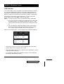
When you invoke the OSD, a screen similar to the one below appears:
!
OSD always starts in List view, with the highlight bar at the same
position it was in the last time it was closed.
!
The Port Number (PN) for each computer on the installation is shown
in the left column of the list.
!
Port numbering details and navigation using the OSD method are
discussed in the following section.
LIST : ALL
SN - PN QV PC NAME
F1 : GOTO
F2 : SCAN
F6 : SET
F4 : QV
F8 : PRV ON
F7 : BRDCST X
01 - 14 ▲ ● DENNIS
01 - 15 ▲
01 - 16 ▲ ● JOSH
02 - 01 ● HUGO
02 - 02 ▲
02 - 03 ▲ TOM
02 - 04 ● JIMMY
02 - 05 ▲ RJ
F3 : LIST
F5 : EDIT
F6 : SET
F9 : NXT ON
2001-06-9
14 CS-1004 / CS-1008 / CS-1016 User Manual

Port Numbering
Each computer on a Master View installation has a two part Port
Number (PN). The first part (in front of the dash) represents the Master
View Station number; the second part (after the dash) represents the
port number on the Master View that the computer is attached to. For
example, a computer attached to port 11 of a fifth stage Master View
would have a port number of 05-11.
OSD Navigation
!
To dismiss the current OSD menu and return to the previous menu
either click on the [X] located at the top righthand corner of the OSD
menu (p.14), or click with the right mouse button. If you are at the
highest menu level, this deactivates OSD.
!
[Esc] cancels the current selection, or dismisses the current menu
and moves back to the menu one level above. If you are at the
highest menu level, it deactivates OSD.
!
Use the Up and Down Arrow Keys or click the Up and Down Triangle
symbols (
st ) to move up or down through the list one line at a time.
!
Use [Pg Up] and [Pg Dn] or click the Up and Down Arrow symbols
("#) to move up or down through the list one screen at a time.
!
To activate a port, move the Highlight Bar to it then press [Enter].
!
After executing any action, you automatically go back to the menu
one level above.
2001-06-9
CS-1004 / CS-1008 / CS-1016 User Manual 15

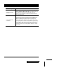
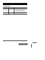
OSD Main Menu Headings
Heading Explanation
SN-PN
This column lists the Port ID numbers (Station Number - Port Number) for
all the CPU ports on the installation. The simplest method to access a
particular computer is move the Highlight Bar to it, then press [Enter].
QV
If a port has been selected for Quick View scanning (see F2 and F4,
below), an arrowhead displays in this column to indicate so.
PC Lists all the computers that are Powered On and are On Line.
NAME
If a port has been given a name (see F5, below), its name appears in this
column.
The Function Keys
Pressing a Function Key brings up a submenu that is used to configure
and control the OSD. For example, you can: rapidly switch to any port;
scan selected ports only; limit the list you wish to view; designate a port
for Quick View scanning; create or edit a port name; or make OSD
setting adjustments.
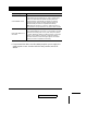
!
F1 GOTO:
GoTo allows you to switch directly to a port by either of the following
two methods:
a) Move the Highlight Bar to the port you want then press [Enter].
b) Key in the Port ID or Name, then press [Enter].
Note: GOTO has a special feature that narrows the list of
available choices as you type the name. For example, if the
first letter you type is a, the list only displays those ports
whose names begin with a. If the next letter you type is b,
the list is further narrowed down to only those ports whose
names begin with ab, etc.
To return to the OSD Main Menu without making a choice, press
[Esc].
2001-06-9
16 CS-1004 / CS-1008 / CS-1016 User Manual
Page is loading ...
Page is loading ...
Page is loading ...
Page is loading ...
Page is loading ...
Page is loading ...
Page is loading ...
Page is loading ...
Page is loading ...
Page is loading ...
Page is loading ...
Page is loading ...
-
 1
1
-
 2
2
-
 3
3
-
 4
4
-
 5
5
-
 6
6
-
 7
7
-
 8
8
-
 9
9
-
 10
10
-
 11
11
-
 12
12
-
 13
13
-
 14
14
-
 15
15
-
 16
16
-
 17
17
-
 18
18
-
 19
19
-
 20
20
-
 21
21
-
 22
22
-
 23
23
-
 24
24
-
 25
25
-
 26
26
-
 27
27
-
 28
28
-
 29
29
-
 30
30
-
 31
31
-
 32
32


Ask a question and I''ll find the answer in the document
Finding information in a document is now easier with AI
Related papers
Other documents
-
ATEN Technology CS-1008 User manual
-
Hawking Technology CS152F User manual
-
-
-
Honeywell HD-DVR-1004 User manual
-
-
-
 Koller-Craft Plastic RPD-1158 User manual
-
Quanmax RPD-1171 User manual
-
Digitus DS-13112 Owner's manual
